EP1881302A1 - Encodeur à arbre creux pourvu d'un capot de protection d'arbres de moteurs - Google Patents
Encodeur à arbre creux pourvu d'un capot de protection d'arbres de moteurs Download PDFInfo
- Publication number
- EP1881302A1 EP1881302A1 EP06015282A EP06015282A EP1881302A1 EP 1881302 A1 EP1881302 A1 EP 1881302A1 EP 06015282 A EP06015282 A EP 06015282A EP 06015282 A EP06015282 A EP 06015282A EP 1881302 A1 EP1881302 A1 EP 1881302A1
- Authority
- EP
- European Patent Office
- Prior art keywords
- motor shaft
- protection cap
- hollow shaft
- encoder
- shaft encoder
- Prior art date
- Legal status (The legal status is an assumption and is not a legal conclusion. Google has not performed a legal analysis and makes no representation as to the accuracy of the status listed.)
- Withdrawn
Links
- 230000001681 protective effect Effects 0.000 title claims abstract description 17
- 239000000853 adhesive Substances 0.000 claims description 2
- 230000001070 adhesive effect Effects 0.000 claims description 2
- 238000007789 sealing Methods 0.000 claims 2
- 239000002932 luster Substances 0.000 claims 1
- 230000004323 axial length Effects 0.000 description 6
- 238000011156 evaluation Methods 0.000 description 4
- 230000008901 benefit Effects 0.000 description 3
- 238000005259 measurement Methods 0.000 description 3
- 230000006378 damage Effects 0.000 description 2
- 238000013461 design Methods 0.000 description 2
- 238000004519 manufacturing process Methods 0.000 description 2
- 239000000243 solution Substances 0.000 description 2
- 230000007704 transition Effects 0.000 description 2
- 208000027418 Wounds and injury Diseases 0.000 description 1
- 238000013459 approach Methods 0.000 description 1
- 230000005540 biological transmission Effects 0.000 description 1
- 230000008859 change Effects 0.000 description 1
- 230000008878 coupling Effects 0.000 description 1
- 238000010168 coupling process Methods 0.000 description 1
- 238000005859 coupling reaction Methods 0.000 description 1
- 238000002347 injection Methods 0.000 description 1
- 239000007924 injection Substances 0.000 description 1
- 208000014674 injury Diseases 0.000 description 1
- 238000009434 installation Methods 0.000 description 1
- 238000012423 maintenance Methods 0.000 description 1
- 230000003287 optical effect Effects 0.000 description 1
- 230000008439 repair process Effects 0.000 description 1
Images

Classifications
-
- G—PHYSICS
- G01—MEASURING; TESTING
- G01D—MEASURING NOT SPECIALLY ADAPTED FOR A SPECIFIC VARIABLE; ARRANGEMENTS FOR MEASURING TWO OR MORE VARIABLES NOT COVERED IN A SINGLE OTHER SUBCLASS; TARIFF METERING APPARATUS; MEASURING OR TESTING NOT OTHERWISE PROVIDED FOR
- G01D11/00—Component parts of measuring arrangements not specially adapted for a specific variable
- G01D11/24—Housings ; Casings for instruments
Definitions
- the invention relates to a hollow shaft encoder with motor shaft protection cap according to the preamble of claim 1.
- Such hollow shaft shaft encoders with motor shaft protection cap are already numerous known from the prior art, wherein the motor shaft of a motor whose parameters such. Speed or position to be determined, is guided by the hollow shaft of the encoder and stored there.
- the inner bearing ring of the hollow shaft of the encoder is fixed to the motor shaft of the motor non-positively and / or positively and rotates at the same speed, with the outer sensor ring of the encoder is fixed.
- a parameter to be determined eg speed or position motor shaft
- proportional measurement signal is generated, which outputs via an interface unit of the encoder to an external forming and evaluation unit optionally with measuring signal memory and display becomes.
- the interface unit of the rotary encoder is in the simplest case a plug contact strip, but may also already be equipped with a first internal forming unit, or even contain an internal evaluation, which can replace the external evaluation.
- the rotary encoder is mounted at the motor end and the motor shaft itself passes through the hollow shaft encoder.
- the unprotected shaft may cause injury.
- a protective cap is mounted on the rotary encoder or on the shaft, which is previously fixed in the prior art with a plurality of screws. Since this shaft is used to manually move the elevator up or down when the machine fails, the protective cap must be removed from the shaft encoder again. The disassembly of the cap must be done with an appropriate tool, especially a small wrench, which is very tedious and time consuming.
- Object of the present invention is to develop a generic hollow shaft encoder with motor shaft protection cap such that it is cheaper and easier in design, manufacture, assembly, warehousing, maintenance and repair.
- the invention is characterized by the features of claim 1.
- Significant features are that the connection between the motor shaft cap and hollow shaft encoder via repeatedly releasable and connectable non-positive and / or positive connection means is accomplished via a relative movement between the motor shaft protection cap and hollow shaft encoder, and that the hollow shaft encoder all for the recording and output of the measuring signals includes electrical and mechanical components and at the Motor shaft protection cap no electrical or mechanical components for recording and output of the measuring signals are attached.
- the advantage here is that, regardless of the axial length of the free end of the motor shaft, a hollow shaft encoder can be used with all the necessary electrical and mechanical components for receiving and outputting the measurement signals and a correspondingly adapted in the axial length, simple and inexpensive motor shaft Protective cap.
- a hollow shaft encoder can be used with all the necessary electrical and mechanical components for receiving and outputting the measurement signals and a correspondingly adapted in the axial length, simple and inexpensive motor shaft Protective cap.
- the hollow shaft encoder according to the invention with motor shaft protection cap is thus considerably cheaper in all areas, as well as easier to handle.
- Another advantage is that a rapid disassembly of the protective cap is possible, which is very important especially in safety-relevant applications, such as in the evacuation of elevators, where almost every second counts. That it does not take long to search for a tool to disassemble the protective cap.
- the solution is an integrated solution in the encoder itself, i.
- the attachment of the protective cap is integrated in the cover or the cap of the rotary encoder. That Also, the cap can be mounted and disassembled especially without tools, this makes in particular a bayonet in the cap itself possible.
- connection means such as Retainer connections, clamped connections, snap-in / snap-in connections, Velcro fasteners, repeatedly releasable and connectable bonds eg by means of double-sided ring-shaped adhesive strips, direct threaded connection between hollow shaft encoder and motor shaft protection cap, toggle joint, splint connection, shaft eyelet hinge connection, etc.
- hollow shaft encoders and motor shaft protection cap are coupled to one another axially on the end face, but in other embodiments may be connected to their respective sheaths.
- the hollow shaft encoder may be at least partially received in an axial recess in the motor shaft cap and the inner shell of the motor shaft protection cap rest on the outer surface of the hollow shaft encoder.
- the motor shaft protective cap can be accommodated at least partially in an axial recess in the hollow shaft encoder and the outer casing of the motor shaft protection cap abut against an inner jacket of the hollow shaft encoder.
- the front-side free edge of the motor shaft protection cap can be accommodated in a circumferential annular groove in the end face of the hollow shaft encoder and fixed there force and / or positive fit.
- Another feature of the closure of a hollow shaft encoder can be any other geometric shape of the cap. For example, shorter or flatter shape to close and / or seal the rear shaft end of the encoder.
- the motor shaft protective cap is cup-shaped and has a conical tapering away from the hollow shaft encoder shape.
- the shape can also be purely cylindrical, hemispherical or partially spherical, rotationally elliptical or parabolic (egg shape) or any other rotationally symmetrical pot-like shape.
- the shape of the housing of the hollow shaft encoder is preferably cylindrical, with the electrical connections for the power supply and the signal lines projecting radially away from the outer jacket.
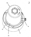
- the hollow shaft encoder 1 is shown with motor shaft protection cap 2 in the assembled state, wherein the motor shaft protection cap 2 is connected via a 3-leaf bayonet connection 3 with the hollow shaft encoder 1.
- the motor shaft cap 2 for mounting the motor shaft cap 2 can be placed in three different positions on the front side of the hollow shaft encoder 1 and then rotated in the clockwise or counterclockwise direction until the wings 8, 11 (see Figures 2 and 3) of the hollow shaft encoder 1 and the motor shaft protection cap 2 come to lie axially one above the other and thus an axial withdrawal is no longer possible.
- an additional catch 4 can be provided between the hollow shaft encoder 1 and the motor shaft protection cap 2.
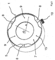
- FIG. 2 now shows the hollow shaft encoder 1, which includes a cylindrical housing 5, in the interior of the complete electrical and mechanical components are accommodated for a fully functional hollow shaft encoder.
- a recess 7 for the bayonet connection 3 is then present, which can be milled or introduced in the injection mold as a "negative".
- the recess 7 includes three evenly distributed over the circumference arranged wings 8, which have a larger inner diameter "di", as the diameter of the Through hole 6.
- the inner diameter di is, however, smaller than the outer diameter "da" of the three protrusions 9 for threading the wings 11 (see FIG. 3) of the motor shaft protection cap. 2
- the outlet and access 10 is provided for the electrical cable for supplying the necessary el. Energy and for dissipating the measurement signals generated in the encoder 1.
- the outlet and access 10 for the electrical cable is here by way of example provided with a thread for coupling to a transmission cable and a forming and evaluation unit (not shown), but may be designed differently in other embodiments, such. as a frictionally engaged connector or as a screwed or clamped terminal block.
- FIG. 3 now shows the motor shaft protective cap 2, which has a cup-shaped basic shape, wherein extending from a circular base plate 12, a cone-shaped jacket 13 axially in the direction of a radial projection in the form of the three wings 11 opening.
- the three wings 11 are arranged uniformly on the circumference, between which three recesses 14 are located.
- the bayonet joint 3 may be present, depending on requirements, but preferred are three wings 8 on the hollow shaft encoder 1 and three wings 11 on the motor shaft protection cap 2.
- the wings 8, 11 also need not necessarily be evenly distributed circumferentially, but may include angles other than 120 ° (3 wings), 180 ° (2 wings), 90 ° (4 wings), 60 ° (6 wings) between them.
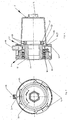
- FIG 4 is a longitudinal section through Figure 1, wherein it can be seen that between the hollow shaft encoder 1 and motor shaft protection cap 2 in the field of Bayonet joint 3, an O-ring 16 is introduced as a seal, which is located in an annular groove 27, which are located in the annular transition region 28 between shell 13 and wings 11 and recesses 14.
- the hollow shaft encoder 1 has the hollow encoder shaft 17 which is rotatably supported by two ball bearings 18 to the stator 19 of the hollow shaft encoder 1.
- the hollow shaft encoder 1 pushed onto the motor shaft is here e.g. mounted on the front side via a shaft attachment 20 with threaded disc 21 and retaining ring 22 against axial withdrawal on the motor shaft (not shown).
- An additional anti-rotation (e.g., key) of the hollow shaft encoder 1 on the motor shaft may be provided in addition to the non-positive fit 23.
- other types of mounting of the hollow shaft encoder 1 on the encoder shaft 17 are possible, e.g. with so-called torque arms.
- FIG. 5 also shows the plan view of FIG. 1 or side view from the right on FIG. 4.
- Position 24 shows a further latching on the undersides of the wings 8 of the hollow shaft encoder 1, in addition or as an alternative to the latching on the wings 11 of the motor shafts -Protective cap. It can thereby be set a closing direction 25 and opening direction 26, but also a spin in both directions be possible.
Landscapes
- Physics & Mathematics (AREA)
- General Physics & Mathematics (AREA)
Priority Applications (1)
| Application Number | Priority Date | Filing Date | Title |
|---|---|---|---|
| EP06015282A EP1881302A1 (fr) | 2006-07-21 | 2006-07-21 | Encodeur à arbre creux pourvu d'un capot de protection d'arbres de moteurs |
Applications Claiming Priority (1)
| Application Number | Priority Date | Filing Date | Title |
|---|---|---|---|
| EP06015282A EP1881302A1 (fr) | 2006-07-21 | 2006-07-21 | Encodeur à arbre creux pourvu d'un capot de protection d'arbres de moteurs |
Publications (1)
| Publication Number | Publication Date |
|---|---|
| EP1881302A1 true EP1881302A1 (fr) | 2008-01-23 |
Family
ID=37441797
Family Applications (1)
| Application Number | Title | Priority Date | Filing Date |
|---|---|---|---|
| EP06015282A Withdrawn EP1881302A1 (fr) | 2006-07-21 | 2006-07-21 | Encodeur à arbre creux pourvu d'un capot de protection d'arbres de moteurs |
Country Status (1)
| Country | Link |
|---|---|
| EP (1) | EP1881302A1 (fr) |
Citations (5)
| Publication number | Priority date | Publication date | Assignee | Title |
|---|---|---|---|---|
| DE3939868A1 (de) * | 1989-12-01 | 1991-06-06 | Huebner Elektromasch Ag | Drehzahlaufnehmer fuer buerstenlose motoren |
| US5057684A (en) * | 1990-08-30 | 1991-10-15 | Robbins & Myers/Electro-Craft, A Wholly Owned Sub. Of Robbins & Myers, Inc. | Unitary aligning and gapping apparatus for modular optical shaft encoder |
| WO1996035934A1 (fr) * | 1995-05-11 | 1996-11-14 | Sydney Smith Dennis Limited | Boitier pour un instrument analogique |
| DE19923900A1 (de) * | 1999-05-25 | 2000-11-30 | Pwb Ruhlatec Ind Prod Gmbh | Encoder mit zusammensteckbarem Gehäuse |
| EP1715300A2 (fr) * | 2005-04-21 | 2006-10-25 | Hengstler GmbH | Encodeur à arbre creux pourvu d'un capot de protection d'arbres de moteurs |
-
2006
- 2006-07-21 EP EP06015282A patent/EP1881302A1/fr not_active Withdrawn
Patent Citations (5)
| Publication number | Priority date | Publication date | Assignee | Title |
|---|---|---|---|---|
| DE3939868A1 (de) * | 1989-12-01 | 1991-06-06 | Huebner Elektromasch Ag | Drehzahlaufnehmer fuer buerstenlose motoren |
| US5057684A (en) * | 1990-08-30 | 1991-10-15 | Robbins & Myers/Electro-Craft, A Wholly Owned Sub. Of Robbins & Myers, Inc. | Unitary aligning and gapping apparatus for modular optical shaft encoder |
| WO1996035934A1 (fr) * | 1995-05-11 | 1996-11-14 | Sydney Smith Dennis Limited | Boitier pour un instrument analogique |
| DE19923900A1 (de) * | 1999-05-25 | 2000-11-30 | Pwb Ruhlatec Ind Prod Gmbh | Encoder mit zusammensteckbarem Gehäuse |
| EP1715300A2 (fr) * | 2005-04-21 | 2006-10-25 | Hengstler GmbH | Encodeur à arbre creux pourvu d'un capot de protection d'arbres de moteurs |
Similar Documents
| Publication | Publication Date | Title |
|---|---|---|
| DE19629585C2 (de) | Winkelmeßeinrichtung | |
| DE102007014714B4 (de) | Spindelmotor | |
| EP3911475B1 (fr) | Dispositif de serrage | |
| DE102014118429A1 (de) | Lenkvorrichtung zur Verwendung in einer Solarnachführungsanlage | |
| DE3605569A1 (de) | Schluesselloses bohrfutter sowie verfahren zur herstellung von schluessellosen bohrfuttern | |
| DE202016106597U1 (de) | Mischwelle | |
| EP2626567A1 (fr) | Boîtier de pompe | |
| EP1715300B1 (fr) | Encodeur à arbre creux pourvu d'un capot de protection d'arbres de moteurs | |
| WO2001036903A1 (fr) | Capteur de deplacement a cable de mesure | |
| WO2014102173A2 (fr) | Groupe motopompe | |
| EP4158758B1 (fr) | Entraînement doté d'un carter, d'une plaque d'adaptation et d'un capot de recouvrement | |
| DE60220476T2 (de) | Anordnung einer Ausgangswelle für das Steuersystem einer Rakete | |
| DE202014105982U1 (de) | Lenkvorrichtung zur Verwendung in einer Solarnachführungsanlage | |
| EP2750269B1 (fr) | Groupe motopompe | |
| DE10140406B4 (de) | Verschluss-System für ein zylindrisches Kunststoffgehäuse | |
| EP0955479A2 (fr) | Dispositif d'assemblage d'éléments de construction | |
| EP2538526B1 (fr) | Moteur d'engrenage triphasé et composants de celui-ci | |
| WO2014180708A1 (fr) | Ensemble pompe | |
| EP3924630B1 (fr) | Ensemble pour le raccordement par serrage d'un arbre, boîte de vitesses à trains épicycloïdaux et procédé pour leur fabrication | |
| EP1517120B1 (fr) | Capteur de rotation | |
| DE20310503U1 (de) | Meßpunkt-Bolzen | |
| DE1575250B1 (de) | Vorrichtung zum verstellbaren Verbinden eines Ansatzteiles mit einem Gehaeuseteil | |
| EP4390138B1 (fr) | Pompe centrifuge et procédé de fabrication d'une pompe centrifuge | |
| DE112005003588T5 (de) | Verfahren zum Verbinden und Festlegen einer Kugelumlaufspindelwelle an einer Motorwelle | |
| DE102010050756B4 (de) | Antriebsvorrrichtung |
Legal Events
| Date | Code | Title | Description |
|---|---|---|---|
| PUAI | Public reference made under article 153(3) epc to a published international application that has entered the european phase |
Free format text: ORIGINAL CODE: 0009012 |
|
| AK | Designated contracting states |
Kind code of ref document: A1 Designated state(s): AT BE BG CH CY CZ DE DK EE ES FI FR GB GR HU IE IS IT LI LT LU LV MC NL PL PT RO SE SI SK TR |
|
| AX | Request for extension of the european patent |
Extension state: AL BA HR MK YU |
|
| 17P | Request for examination filed |
Effective date: 20080714 |
|
| 17Q | First examination report despatched |
Effective date: 20080819 |
|
| AKX | Designation fees paid |
Designated state(s): DE FR GB IT |
|
| STAA | Information on the status of an ep patent application or granted ep patent |
Free format text: STATUS: THE APPLICATION IS DEEMED TO BE WITHDRAWN |
|
| 18D | Application deemed to be withdrawn |
Effective date: 20090303 |