EP1882452A1 - Formung einer Knochenplatte - Google Patents
Formung einer Knochenplatte Download PDFInfo
- Publication number
- EP1882452A1 EP1882452A1 EP07252914A EP07252914A EP1882452A1 EP 1882452 A1 EP1882452 A1 EP 1882452A1 EP 07252914 A EP07252914 A EP 07252914A EP 07252914 A EP07252914 A EP 07252914A EP 1882452 A1 EP1882452 A1 EP 1882452A1
- Authority
- EP
- European Patent Office
- Prior art keywords
- plate
- bone
- holes
- tips
- guide
- Prior art date
- Legal status (The legal status is an assumption and is not a legal conclusion. Google has not performed a legal analysis and makes no representation as to the accuracy of the status listed.)
- Withdrawn
Links
Images








Classifications
-
- A—HUMAN NECESSITIES
- A61—MEDICAL OR VETERINARY SCIENCE; HYGIENE
- A61B—DIAGNOSIS; SURGERY; IDENTIFICATION
- A61B17/00—Surgical instruments, devices or methods
- A61B17/16—Instruments for performing osteoclasis; Drills or chisels for bones; Trepans
- A61B17/17—Guides or aligning means for drills, mills, pins or wires
- A61B17/1728—Guides or aligning means for drills, mills, pins or wires for holes for bone plates or plate screws
-
- A—HUMAN NECESSITIES
- A61—MEDICAL OR VETERINARY SCIENCE; HYGIENE
- A61B—DIAGNOSIS; SURGERY; IDENTIFICATION
- A61B17/00—Surgical instruments, devices or methods
- A61B17/56—Surgical instruments or methods for treatment of bones or joints; Devices specially adapted therefor
- A61B17/58—Surgical instruments or methods for treatment of bones or joints; Devices specially adapted therefor for osteosynthesis, e.g. bone plates, screws or setting implements
- A61B17/68—Internal fixation devices, including fasteners and spinal fixators, even if a part thereof projects from the skin
- A61B17/80—Cortical plates, i.e. bone plates; Instruments for holding or positioning cortical plates, or for compressing bones attached to cortical plates
-
- A—HUMAN NECESSITIES
- A61—MEDICAL OR VETERINARY SCIENCE; HYGIENE
- A61B—DIAGNOSIS; SURGERY; IDENTIFICATION
- A61B17/00—Surgical instruments, devices or methods
- A61B17/56—Surgical instruments or methods for treatment of bones or joints; Devices specially adapted therefor
- A61B17/58—Surgical instruments or methods for treatment of bones or joints; Devices specially adapted therefor for osteosynthesis, e.g. bone plates, screws or setting implements
- A61B17/68—Internal fixation devices, including fasteners and spinal fixators, even if a part thereof projects from the skin
- A61B17/80—Cortical plates, i.e. bone plates; Instruments for holding or positioning cortical plates, or for compressing bones attached to cortical plates
- A61B17/8052—Cortical plates, i.e. bone plates; Instruments for holding or positioning cortical plates, or for compressing bones attached to cortical plates immobilised relative to screws by interlocking form of the heads and plate holes, e.g. conical or threaded
-
- A—HUMAN NECESSITIES
- A61—MEDICAL OR VETERINARY SCIENCE; HYGIENE
- A61B—DIAGNOSIS; SURGERY; IDENTIFICATION
- A61B17/00—Surgical instruments, devices or methods
- A61B17/56—Surgical instruments or methods for treatment of bones or joints; Devices specially adapted therefor
- A61B17/58—Surgical instruments or methods for treatment of bones or joints; Devices specially adapted therefor for osteosynthesis, e.g. bone plates, screws or setting implements
- A61B17/88—Osteosynthesis instruments; Methods or means for implanting or extracting internal or external fixation devices
- A61B17/8863—Apparatus for shaping or cutting osteosynthesis equipment by medical personnel
-
- A—HUMAN NECESSITIES
- A61—MEDICAL OR VETERINARY SCIENCE; HYGIENE
- A61B—DIAGNOSIS; SURGERY; IDENTIFICATION
- A61B90/00—Instruments, implements or accessories specially adapted for surgery or diagnosis and not covered by any of the groups A61B1/00 - A61B50/00, e.g. for luxation treatment or for protecting wound edges
- A61B90/90—Identification means for patients or instruments, e.g. tags
- A61B90/92—Identification means for patients or instruments, e.g. tags coded with colour
-
- A—HUMAN NECESSITIES
- A61—MEDICAL OR VETERINARY SCIENCE; HYGIENE
- A61B—DIAGNOSIS; SURGERY; IDENTIFICATION
- A61B17/00—Surgical instruments, devices or methods
- A61B17/16—Instruments for performing osteoclasis; Drills or chisels for bones; Trepans
- A61B17/17—Guides or aligning means for drills, mills, pins or wires
- A61B17/1739—Guides or aligning means for drills, mills, pins or wires specially adapted for particular parts of the body
- A61B17/1782—Guides or aligning means for drills, mills, pins or wires specially adapted for particular parts of the body for the hand or wrist
-
- A—HUMAN NECESSITIES
- A61—MEDICAL OR VETERINARY SCIENCE; HYGIENE
- A61B—DIAGNOSIS; SURGERY; IDENTIFICATION
- A61B17/00—Surgical instruments, devices or methods
- A61B17/56—Surgical instruments or methods for treatment of bones or joints; Devices specially adapted therefor
- A61B17/58—Surgical instruments or methods for treatment of bones or joints; Devices specially adapted therefor for osteosynthesis, e.g. bone plates, screws or setting implements
- A61B17/68—Internal fixation devices, including fasteners and spinal fixators, even if a part thereof projects from the skin
- A61B17/80—Cortical plates, i.e. bone plates; Instruments for holding or positioning cortical plates, or for compressing bones attached to cortical plates
- A61B17/8061—Cortical plates, i.e. bone plates; Instruments for holding or positioning cortical plates, or for compressing bones attached to cortical plates specially adapted for particular bones
-
- A—HUMAN NECESSITIES
- A61—MEDICAL OR VETERINARY SCIENCE; HYGIENE
- A61B—DIAGNOSIS; SURGERY; IDENTIFICATION
- A61B17/00—Surgical instruments, devices or methods
- A61B17/56—Surgical instruments or methods for treatment of bones or joints; Devices specially adapted therefor
- A61B17/58—Surgical instruments or methods for treatment of bones or joints; Devices specially adapted therefor for osteosynthesis, e.g. bone plates, screws or setting implements
- A61B17/68—Internal fixation devices, including fasteners and spinal fixators, even if a part thereof projects from the skin
- A61B17/80—Cortical plates, i.e. bone plates; Instruments for holding or positioning cortical plates, or for compressing bones attached to cortical plates
- A61B17/8085—Cortical plates, i.e. bone plates; Instruments for holding or positioning cortical plates, or for compressing bones attached to cortical plates with pliable or malleable elements or having a mesh-like structure, e.g. small strips
-
- A—HUMAN NECESSITIES
- A61—MEDICAL OR VETERINARY SCIENCE; HYGIENE
- A61B—DIAGNOSIS; SURGERY; IDENTIFICATION
- A61B17/00—Surgical instruments, devices or methods
- A61B17/56—Surgical instruments or methods for treatment of bones or joints; Devices specially adapted therefor
- A61B17/58—Surgical instruments or methods for treatment of bones or joints; Devices specially adapted therefor for osteosynthesis, e.g. bone plates, screws or setting implements
- A61B17/88—Osteosynthesis instruments; Methods or means for implanting or extracting internal or external fixation devices
- A61B17/8875—Screwdrivers, spanners or wrenches
- A61B17/8877—Screwdrivers, spanners or wrenches characterised by the cross-section of the driver bit
- A61B17/888—Screwdrivers, spanners or wrenches characterised by the cross-section of the driver bit the driver bit acting on the central region of the screw head
-
- A—HUMAN NECESSITIES
- A61—MEDICAL OR VETERINARY SCIENCE; HYGIENE
- A61B—DIAGNOSIS; SURGERY; IDENTIFICATION
- A61B17/00—Surgical instruments, devices or methods
- A61B17/56—Surgical instruments or methods for treatment of bones or joints; Devices specially adapted therefor
- A61B17/58—Surgical instruments or methods for treatment of bones or joints; Devices specially adapted therefor for osteosynthesis, e.g. bone plates, screws or setting implements
- A61B17/88—Osteosynthesis instruments; Methods or means for implanting or extracting internal or external fixation devices
- A61B17/8875—Screwdrivers, spanners or wrenches
- A61B17/8886—Screwdrivers, spanners or wrenches holding the screw head
- A61B17/8888—Screwdrivers, spanners or wrenches holding the screw head at its central region
-
- A—HUMAN NECESSITIES
- A61—MEDICAL OR VETERINARY SCIENCE; HYGIENE
- A61B—DIAGNOSIS; SURGERY; IDENTIFICATION
- A61B90/00—Instruments, implements or accessories specially adapted for surgery or diagnosis and not covered by any of the groups A61B1/00 - A61B50/00, e.g. for luxation treatment or for protecting wound edges
- A61B90/06—Measuring instruments not otherwise provided for
- A61B2090/062—Measuring instruments not otherwise provided for penetration depth
Definitions
- This invention to orthopaedic implants, and specifically to elements to implant and shape a bone plate.
- Alignment and fixation of a fracture are typically performed by one of several methods: casting, external fixation, pinning, and plating.
- Casting is non-invasive, but may not be able to maintain alignment of the fracture where many bone fragments exist. Therefore, as an alternative, external fixators may be used.
- External fixators utilise a method known as ligamentotaxis, which provides distraction forces across the joint and permits the fracture to be aligned based upon the tension placed on the surrounding ligaments.
- ligamentotaxis which provides distraction forces across the joint and permits the fracture to be aligned based upon the tension placed on the surrounding ligaments.
- external fixators can maintain the position of the wrist bones, it may nevertheless be difficult in certain fractures to first provide the bones in proper alignment.
- external fixators are often not suitable for fractures resulting in multiple bone fragments.
- K-wires (Kirschner wires) is an invasive procedure whereby pins are positioned into the various fragments. This is a difficult and time consuming procedure that provides limited fixation if the bone is comminuted or osteoporotic.
- Plating utilises a stabilizing metal plate typically placed against the bone, fixed-angle fasteners (which may have threaded or non-threaded shafts) positioned through the plate and entering drilled holes adjacent an articular bone surface, and cortical screws extending from the plate into holes drilled in the bone to provide stabilised fracture fixation.
- a plate which particularly adapted to treat dorsally displaced metaphyseal fractures from the volar side of the wrist is disclosed in US-A-2004/0193164 .
- Fragment plates are commonly used to fixate fractures along a bone, e.g., along the diaphysis or at specific diaphyseal-metaphyseal or metaphyseal locations. Such plates are generally elongate, L-shaped, Y-shaped or have another shape which is suited for placement on a portion of a bone. The plates can be of varying length depending upon the intended fixation application. When fragment plates are provided with threaded holes they are subject to the same practical labour intensity for use as presented above with respect to the volar plates, so that it can be labourious to attach a drill guide at each threaded hole for drilling a hole in alignment with the axis of the hole for receiving the fixed angle fastener within it.
- the anatomy for which the fragment plates are designed often differs from the exact contours of the bone contacting surfaces of the plates.
- Some fragment plates have been designed to be shaped away from the bone for a better anatomical fit.
- presently available plating systems are not well adapted for reconfiguration. Therefore, it has been necessary to shape a plate off the target bone with bending tools, remove the bending tools, place the plate in position on the bone to which the plate will eventually be attached, approximate the additional amount of reconfiguring required, remove the plate, and repeat the process until the plate approximately conforms to the shape of the bone.
- a plate may need to be re-contoured along three axes, and it has been difficult to transfer the contours of the anatomy to a stiff metal plate, especially when such reshaping is done at a distance from the bone.
- the problems with shaping a plate are compounded when the plate has threaded holes for receiving fasteners.
- inserting bending tools into the threaded holes of the plate and applying a force to the plate with the bending tools may distort the threads making such holes unable to accept their threaded fasteners.
- drill guide tips are pre-assembled into at least one and preferably each of the threaded holes of the plate, so that the surgeon does not have to thread the drill guide with the plate positioned on the bone.
- the pre-assembly can be done by the operating room technician or at the factory.
- the drill guide tips may be reusable or disposable. The tips are sufficiently short that they do not interfere with adjacent tips or adjacent structure on the plate or intended to be inserted through the plate.
- a nest of short pins is placed beneath the plate such that the pins extend through the holes in the plate along the same angles as the axes of the holes.
- the pins then guide the tips to be threaded into the holes at the correct angle.
- no nest is utilised and the tips are individually guided into the holes at the appropriate angle. With respect to a fragment plate, such angle is typically normal to the bone contacting surface of the plate.
- the tips are two options for using the tips as drill guides.
- One is to attach a drill guide extension.
- the tip and extension together function as a conventional drill guide. After drilling, the extension is used to remove the tip from the plate. According to another use, the tip is used as a guide for a drill bit without any additional extension and then removed with a separate tool.
- the guide tips have purpose other than for guiding a drill.
- the guide tips can also be used in conjunction with plate bending tools, and are particularly advantageous when the guide tips are pre-assembled on a fragment plate having a plurality of spaced apart fixed angle holes separated by a plate portion which can be deformed under force.
- Preferably two bending tools are used together to bend the plate, and the bending tools have first and second ends which are at least partially inserted into guide tips in two holes in the plate.
- Torque is applied by coupling the first ends of each of the tools to the guide tips inserted in threaded holes and manipulating the tools, lateral bending forces (i.e., bending within the plane of the plate) are applied with the second ends in the guide tips, and longitudinal bending forces are applied with the first ends or a combination of the first and second ends in the guide tips.
- the bending tools can be operated and forces can be applied to reshape the plate with the plate positioned directly on the bone to reshape the plate in close conformance to the bone surface.
- bending tools are removed and the guide tips can be used as discussed above as drill guides to drill holes into bone beneath that portion of the plate. Fixed angle screws are then used to couple that portion of the fragment plate to the bone.
- the adjacent portion of the plate is then shaped and fixed to the bone in a like manner with the process repeated until the entire plate is shaped and coupled to the bone.
- the technique of the invention can facilitate the drilling of holes in bone in alignment with the threaded holes in a bone plate.
- the technique of the invention can help to minimise the difficulties presented in connecting a drill guide in alignment with a threaded fixed angle hole in a bone plate at the time of surgery.
- the technique of the invention can provide a system to reshape a plate while the plate is located on the bone.
- the technique of the invention can provide a system which permits reshaping of the plate in three dimensions.
- the technique of the invention can provide a system which protects the threads of fixed angle holes during plate reshaping.
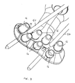
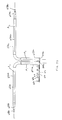
- Fig. 1 shows a bone plate 10 which has inner or lower (bone-facing) and outer or upper (bone-opposing) surfaces 10a, 10b. Either or each of these surfaces may be contoured generally to follow a surface of a target bone (or bones) for which the bone plate is intended, so that the bone plate maintains a low profile and fits onto the bone(s).
- the inner surface 10a of the plate may be generally complementary in contour to the bone surface.
- the outer surface 10b may correspond in contour to the bone surface and may be generally complementary to the inner surface of the plate.
- Bone plate 10 shown is particularly for placement over the volar side of the distal radius.
- the bone plate 10 includes a plurality of threaded peg holes 12 for threadably receiving the heads of pegs or locking screws (not shown) therein and relatively smaller alignment holes 14 sized to closely receive K-wires in a fixed angle orientation.
- the axes of the peg holes are all oblique relative to each other.
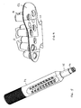
- a drill guide tip 16 is shown being pre-assembled into the hole with an insertion tool 18. Referring to Figs.
- the engagement between the insertion tool 18 and tip 16 is a tapered square 20 engaging a circular opening 22, with the edges of the square driver providing sufficient frictional force to rotate the tip into and out of engagement with the plate 10.
- Other suitable engagements may be used as well.
- Pre-assembly of the tips 16 into the peg holes of the plate 10 is preferably performed so that the surgeon does not have to thread the drill guide tips 16 with the plate once the plate 10 is positioned on the bone during the procedure.
- the pre-assembly can be done by the operating room technician or at the factory.
- a nest of short pins 24 is placed beneath the plate such that the pins extend through the holes in the plate along the same angles as the axes of the holes.
- the pins 24 then guide the tips to be threaded into the holes at the correct angle. With respect to a fragment plate, such angle is typically normal to the bone contacting surface of the plate.
- the pins 24 and insertion tool 18 are sized such that they do not interfere with each other. Alternatively, no nest is utilised and the tips 16 are individually guided into the holes at the appropriate angle.
- the drill guide tips 16 may be reusable or disposable.
- the tips 16 have a frustoconically tapered upper portion 30 and lower threaded portion 32, and are sufficiently short so that they do not interfere with adjacent tips, adjacent structure on the plate, or structure intended to be inserted through the plate, e.g., K-wires 50 through alignment holes 14.
- the upper portion 30 may be cylindrical.
- the lower threaded portion 32 of the tips does not have to be as long as conventional drill guides, as the threading into the plate is done away from the surgical environment under easier conditions, whether at the factory (best case) or pre-implantation at the medical facility. Shortening the threaded portion reduces protrusion of the guide tip below the plate relative to convention drill guides, allowing the plate 10 to sit closer to the bone while drilling, as discussed further below.
- the drill guide tips also eliminate the need to "countersink” holes for a drill guide for the distal row of holes in a distal radius plate. More particularly and for the following reasons, in the prior art it is initially necessary to drill holes in bone through the distal row of threaded peg holes with a drill bit larger than the diameter of the peg shaft which will eventually be inserted through the peg holes.
- the plate is very thin at the distal row.
- the prior art drill guide has a "nose” section which is cylindrical and unthreaded and approximately 0.76 mm (0.030 inch) long, which is slightly longer than the pitch of the peg-hole thread (0.58 mm (0.023 inch)).
- the nose section diameter is just under the inner diameter of thread so that it guides itself with one full turn of the thread and establishes the direction of the hole before the threads are engaged. If the plate thread depth is very small (as is the case for distal holes) there is no room below the plate for the nose section of the drill guide because the bone blocks entry. Thus, countersink holes must be drilled.
- the drill guide tips do not require a "nose” section since they will be assembled with some other guidance (e.g., the above described nest of pins 24) or freehand.
- the drill guide tips can be made very short since they need just to hold on to the threads of the peg holes of a distal radius plate.
- One and one-half threads of engagement has been shown to provide a satisfactory coupling of the tip to the plate, and referring to Fig. 4 provides that the drill guide tip 16 does not protrude through the bottom 52 of the plate 10.
- the fact that drill guide tips are so short results in the plate seating almost completely flush on the bone.
- each tip is preferably approximately 3.8 to 6.35 mm (0.150 to 0.250 inch) in length and certainly less than 25 mm (1 inch). As such, the tip extends a short distance (maximum 25 mm (1 inch) and preferably not more than 6.35 mm (0.25 inch)) above the upper surface (the surface opposite the bone contacting surface) of the plate.
- the tips 16 are used as the sole guide for a drill bit and then removed with a tool similar to the insertion tool 18.
- the length of the tips provides sufficient guidance for the drill bit.
- the inner surface of the tip is preferably hard, especially a metal.
- the tips 16 may be made entirely of metal or have an outer plastic body with an insert moulded metal tube, e.g. hypotube, which is hard and readily available with thin walls.
- a drill guide extension 34 may be attached to the top of the tip 16.
- the tip 16 and extension 34 together function as a full length drill guide.
- the engagement between the drill guide extension 34 over the tip 16 is preferably such that a continuous constant diameter path is provided through the interiors of the extension and tip.
- the end 36 of the extension 34 is preferably stepped to fit the upper portion of the tip. The surgeon drills through the drill guide extension and tip, thereby taking advantage of the longer guidance which may be used in conjunction with a scale and/or gauge to measure the depth of the drilled hole for peg length selection.
- the extension 34 and tip 16 are removed from the plate 10, and the extension 34 may also function as a tool for tip 16 removal.
- the taper at the upper portion 30 (Fig. 2) of the tip provides a means for axial and frictional engagement by the extension 34 which permits rotational engagement. Once removed from the plate, the tip is then is pulled of the extension by hand or may be dispensed into a container without manual contact.
- the drill guide tips have a very conspicuous colour, e.g., green or blue. If made out of metal, it may be desirable to make them out of titanium or aluminium and anodise them in a bright colour that contrasts with the background in the surgical wound and the bone plate.
- a specialised container may be provided, or a dummy plate with threaded holes may be used to attach the tip thereto.
- the tips 116 may have an upper portion 130 with an exterior hex shape, or any non-circular exterior cross-sectional shape that will facilitate torque transmission.
- the surgeon rotates the extension, unthreading the tip.
- the tips 216 may be joined to the extension via one or more lateral protrusions 240 on the body 230 of the tip and corresponding "key slots" 242 in the extension 234.
- the tips 316 may be joined to the extension by providing one or more corners 344 to the inner circular opening 322 of the tip, and one or more outer corresponding corners on the extension which frictionally engage in the tip.
- the tips 416 may include upper radially arranged slots 446 (e.g., 180° or 120° separation) and the extension 434 includes corresponding radially arranged pegs 448 which engage the tips 416 at the slots 446.
- the tips can also be used to facilitate bending of a fragment plate 500 in a manner that does not distort the threads at the holes 502 at which the tips 516 are coupled, as described below.
- the tips 516 are cylindrical having inside corners (similar to corners 344 in Fig. 10) to aid removal and/or extension guide coupling. Such distortion would otherwise prevent the holes 502 from accepting fixed angle fasteners with threaded heads which are later threadably coupled into the threaded holes.
- Bendable plates may have at least one, and generally two or more, distinct anchor (or bone-attachment) portions including a threaded hole and at which the plate is configured to be secured to bone.
- Each anchor portion may be structured for a specific portion of a bone, generally to fit against a surface region of a specific or general bone.
- the bone plate may include a proximal anchor portion for attachment to a more proximal region of a bone, and a distal anchor portion for attachment to a more distal region of the same bone.
- the bone plates may include a support (or buttress) portion connected to an anchor portion.
- the support portion may lack connective features that permit a direct connection of the support portion to the bone with one or more fasteners. Such a support portion may limit movement of a bone fragment using contact between the support portion and the fragment, and may include projections or prongs to engage the fragment more effectively.
- the bone plates described herein may be configured for use on any suitable bone of the human body and/or of another vertebrate species.
- Exemplary bones may include bones of the arms (radius, ulna, humerus), legs (femur, tibia, fibula, patella), hands, feet, the vertebrae, scapulas, pelvic bones, cranial and mandibular bones, the ribs and/or the clavicles, among others.
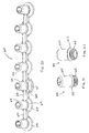
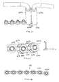
- the fragment plate 500 is generally elongate, preferably designed with a series of alternating round anchor portions 504 and relatively narrower bridge portions 506 that connect the anchor portions together.
- the anchor portions 504 have a diameter DA and a height HA
- the bridge portions 506 have a length LB, a width WB, and height HB.
- diameter DA 5.56 mm (0.22 inch)
- HA 1.52 mm (0.060 inch)
- LB 1.65 mm (0.065 inch)
- WB 2.16 mm (0.085 inch)
- HB 12.74 mm (0.50 inch).
- each bridge portion is preferably less than one half, and more preferably less than forty percent, of the anchor diameter DA.
- the plate includes an inner (bone-facing) surface 512 and an outer (bone-opposing) surface 514.
- a long axis AP defined through the plate 500 may be aligned with the long axis of a corresponding bone or may extend obliquely or transversely relative to the long axis of the bone.
- the dimensions of the anchor and bridge portions 504, 506, and the number of anchor and bridge portions may be varied according to the intended use, for example, to match the plate with a preselected region of bone(s) and/or to a particular injury to the bone.
- the plates may be generally linear for use on the shaft of a long bone or may have a nonlinear shape, such as for use near an end of a bone.
- the plate may be generally T-shaped, with a longer axis for attachment to a shaft portion of a bone, and a transverse portion connected to the longer axis portion, to provide a wider platform for attachment near an end of the bone.
- the transverse portion may be of a different construct, e.g., a plate portion without any bridge portions but multiple threaded holes, as shown in Fig. 1.
- the plate may also be Y-shaped.
- each bone plate may be configured for use on both sides of the body, such as when the bone plates are bilaterally symmetrical.
- each bone plate may be asymmetrical and configured for use on either the left or the right side of the body.
- Threaded holes 502 are provided in the anchor portions 504, and preferably each threaded hole 502 is provided with a guide tip 516.
- the tips may be strategically pre-assembled at locations that are recognised to commonly benefit from contour shaping for the plate 500 depending on the shape of the plate and to best fit on the bone.
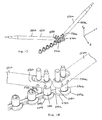
- two preferably identical plate benders (shaping tools) 550a, 550b have ends which can be coupled to the tips 516 and can be used alone or together to contour the plate 500 (Figs. 13 and 14). As described in more detail below, the benders 550a, 550b and tips 516 permit such plate contouring to occur with the plate 500 positioned directly on the bone.
- Each tool described with respect to tool 550a, includes a handle portion 552a and first and second ends 554a, 556a which can be at least partially inserted into the guide tips 516.
- the first end 554a includes a preferably axially directed (or preferably at least directed generally parallel to the longitudinal axis A L of the handle portion 552a) peg element 558a which closely corresponds in size to the inner diameter of a guide tip 516.
- the second end 556a is provide with four peg elements 560a, 562a, 564a, 566a, with two such pegs extending transversely to the longitudinal axis A L of the handle on each side 568a, 570a of the second end 556a.
- the endmost peg element 560a closely corresponds in size to the inner diameter of a guide tip 516 and the inner peg element 562a has a stepped down nipple portion 572a, whereas on the opposite side 570a of the second end the endmost peg element 564a has a stepped down nipple portion 574a stepped down in diameter and the inner peg element 566a closely corresponds in size to the interior of the guide tip 516.
- All the peg elements are preferably generally cylindrical, but may be polygonal or slightly tapered.
- the benders 550a, 550b can be coupled to a fragment plate at the guide tips 516 to apply torque, lateral and longitudinal bending forces to contour the plate; i.e., to bend the plate along x-, y- and z-axes.
- the benders be coupled at adjacent guide tips for localised control of plate shaping.
- the plate is then shaped through a series of shaping steps in which adjacent portions of the plate are sequentially shaped, as needed. Additionally all such shaping, as also discussed further below, can be performed while the plate is positioned on the bone.
- the peg elements 558a, 558b (Fig. 15) at the first ends 554a, 554b of the benders 550a, 550b are inserted into preferably adjacent guide tips 516a, 516b.
- the handle portions 552a, 552b of the benders are then forced laterally relative to each other so as to apply a torque along the bridge portion 506 of the plate between the benders.
- Such torque results in defining a twist in the plate without deformation to the threaded holes to bend the plate along the x-axis.
- lateral bending forces i.e., bending within the plane of the plate
- peg element 566a is inserted into guide tip 516a and the nipple portion 574a of peg element 564a functions as fulcrum (rotational stop) against the bridge portion 506a of the plate to transfer rotational forces applied by the handle portion 552a of bender 550a.
- peg element 560b (not shown, see Fig. 15) is inserted into guide tip 516b and the nipple portion 572b of peg element 562b functions as a fulcrum (rotational stop) against the bridge portion 506b of the plate to transfer rotational forces applied by the handle portion 552b of bender 550b.
- benders 550a, 550b are operated together, the resulting force subjects the plate to lateral bending at the bridge portion 506a located between the plate portions 504a, 504b at which the guide tips are coupled.
- longitudinal bending forces are applied by inserting the peg element at the first end 554a of bender 550a into guide tip 516c and a peg element, e.g. peg element 560b, at the first 554b or second ends 556b (shown) of the second bender 550b into the guide tip 516d.
- the handle portion 552b thereof can be stabilised relative to the bone.
- the handle portion of tool 550a is then manipulated to bend the plate 500 at the bridge portion 504 between the two benders to bend the plate relative to the z-axis.
- a single bender can be used to shape the plate once at least a portion of the plate is fixed relative to the bone. Such is described in more detail below with reference to another embodiment of a bender.
- plate shaping can occur directly on the bone.
- a hole is first drilled through a guide tip at an end of the plate.
- the guide tip is then removed and a threaded fastener is inserted through the threaded hole of the fragment plate and into the drilled hole to couple the plate to the bone.
- the benders are then worked along the plate, moving hole by hole away from the first coupled hole to shape the plate to the bone as described above.
- the plate As the plate is shaped at each hole, if needed, a hole is drilled through the respective guide tip, the guide tip is removed and a threaded fastener is inserted to hold the plate to the bone. One or both of the benders are then moved to subsequent holes along the plate for shaping until the plate is fully contoured and coupled to the bone.
- the plate After the plate is coupled to the bone at an end, the plate is shaped along its entire length prior to coupling to the bone at remaining holes.
- the plate may be shaped to the bone before it is attached at any screw hole. It is recognised that other variations on shaping and coupling can be used.
- a shapeable bone plate 600 is shown with another embodiment of the guide tips 616.
- the plate is substantially as described above with respect to plate 500, including an alternating arrangement of anchor and bridge portions 604, 606.
- Each anchor portion 604 is preferably curved along a constant radius for at least 100° adjacent its adjacent bridge portion, and more preferably approximately 120°, for cooperation with another embodiment of a plate bending tool 650a, 650b, described hereinafter.
- the guide tips 616 each have a first end 618 assembled in a threaded hole in the anchor portion 604, a second end 620 extending above an outer surface 614 of the anchor portion, and a circumferentially extending shoulder 622 disposed between the first and second ends, and preferably in contact with outer surface 614 of the plate 600.
- the shoulder 622 doubles the load carrying capacity of the guide tips 616 relative to the prior guide tips by reducing the load carrying from the thread/thread interface and transferring load carrying to the shoulder/plate interface.
- the second end 620 of the guide tip 616 preferably extends no more than 12.7 mm (0.5 inch), and more preferably is located not more than approximately 6.4 mm (0.25 inch) above the outer surface 614 of the anchor portion.
- a pair of plate benders 650a, 650b is shown coupled to adjacent anchor portions 604a, 604b of the plate 600.
- the plate benders 650a, 650b each include a first end 652a, 652b, a second end 654a, 654b, and a handle 656a, 656b extending between them, with the respective handles 656a, 656b preferably extending in generally opposing directions.
- the first end 652a defines a socket 660a sized to closely receive a guide tip 616, and means for rotationally fixing the first end 652a relative to a portion of the bone plate 600, such as the bridge portion 606.
- the means for rotationally fixing the first end relative to the bone plate are two feet 662a, 664a that straddle the bridge portion 606 of the bone plate.
- the two feet 662a, 664a include curved inner surfaces 666a, 668a that seat about the radiussed portions 670, 672 of the anchor portion 604a to quickly and easily align the bender 656a on the plate.
- the feet 662a, 664a each have a toe end 674a, 676a that abuts the bridge portion 606 at an optimal location to function as a fulcrum for the bender. Referring back to Fig.
- the second ends 654a, 654b of the benders define pegs 678a, 678b that are cylindrical and that step down in diameter from the adjacent portion of the handle.
- the handle 656a, 656b is preferably L-shaped and extends between the respective first and second ends.
- Each handle, e.g., 656a includes a first longitudinal axis A1 extending through its first end 652a and an adjacent portion of the handle and a second longitudinal axis A2 extending through the second end 654a and its adjacent portion of the handle.
- the handle 656a is preferably bent to offset the two axes relative to each other.
- the socket 660a at the first end 652a is offset relative to the second axis A2 by at least approximately 6.4 mm (0.25 inch), more preferably at least 12.7 mm (0.5 inch) (to provide for guide tip and tissue clearance), but preferably by not more than approximately 76.2 (3 inch) (to maintain handle stability and control).
- the benders 650a, 650b are preferably identical with the exception that the handles are bent in opposite directions from each other. The handles are coupled to the plate such that the longitudinal axis A 1 of each handle overlies the respective longitudinal axis of the plate portions surrounding the plate segment which is to be bent.
- An exception is provided at the anchor portion 604a at the end of the plate, where the appropriate bender should be coupled so that the handle extends outward from the plate, rather than over the plate.
- the plate 600 is generally bent so that its inner surface 612 thereof approximates the shape of the bone surface generally in the manner described above. More particularly, referring to Figs. 26 and 27, a bend in the y-axis may be imparted to the plate at the bridge 606 between anchor portions 604a, 604b to which the benders 650a, 650b are coupled by applying a relative rotational force. In imparting such a bend, the feet 662b, 664b of bender 650b stabilise anchor 604b, while the toe 674a of foot 662a functions as a fulcrum and the inner surface 668a of the opposite foot 664a applies the force to the anchor portion 604a to impart the desired bend.
- Fig. 28 shows the plate 600 with a lateral bend imparted between anchor portions 604a and 604b after the benders have been removed from the plate.
- the pegs 678a, 678b at the second ends of the benders can be inserted into the guide tips 616 at preferably adjacent anchor portions and can be manipulated to bend the plate relative to x- and z-axes; i.e., to impart torque and a resulting twist to the plate (x-axis displacement) and to longitudinally bend the plate up and/or down (z-axis displacement).
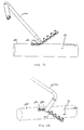
- Fig. 29 shows the benders 650a, 650b imparting a twist to the plate 600; i.e., to rotate anchor portion 604a in the x-axis relative to anchor portion 604b. It is appreciated that the benders may similarly be used to bend the plate along the z-axis.
- Fig. 30 one way to overcome any potential interference is to move the benders 650a, 650b out of plane, but this may impart an x-axis twist to the plate 600, which could be undesired.
- Fig. 31 one solution when working in from the end of the plate (the ends of which are already fixed to the bone 680 by screws 682) is to use a single bender 650a to impart a bend along the z-axis.
- a bend along the x-axis can likewise be imparted. Referring to Fig.
- the bridge portion of the plate be substantially narrower than the anchor portion to facilitate bending, particularly a lateral bend along the y-axis.
- plates with smaller ratios of anchor to bridge widths can also be bent and shaped using the guide tips and tools described herein, and there are circumstances where an overall relatively stiffer plate may be desirable.
- a Y-shaped plate 700 with such a smaller ratio is shown first being torqued along the x-axis to impart a twist (Fig. 34) and then being bent along the z-axis to impart a longitudinal bend (Fig. 35) in accord with the methods described above.
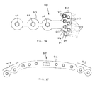
- a volar T-plate 800 is shown in which the axial shaft portion 802 is shapeable and provided with guide tips 816.
- the relatively transverse head portion 803 is substantially non-shapeable, with the exception of an anchor portion 804 coupled by a bridge 806 to the remainder of the head portion 803.
- the anchor portion 804 is thus adapted to be shaped relative to the rest of the head portion to direct a fastener toward the volar marginal fragment.
- all the holes in the head portion are provided with guide tips 817.
- Guide tips 816 and 817 may be different sizes to accommodate relatively different diameter threaded holes in the respective portions of the plate.
- subchondral supports 818 e.g., threaded pegs or screws
- any load on the subchondral supports is transferred back to the axial shaft portion 802 of the plate 800.
- the same principal can be applied to other metaphyseal plates.
- a clavicle plate 900 is shown in Fig. 37.
- the clavicle plate 900 has a relatively rigid non-shapeable central portion 902, and end portions 903 that are shapeable. The same principal can be applied to other diaphyseal places.
- the tips and benders have been shown with respect to a volar plate for dorsally displaced fractures and several fragment plates, it will be appreciated that the tips may be used in conjunction with threaded holes on other bone plates as well. For example, the tips may be used in conjunction with any plate for which they would provide advantage.
- one or more benders may be used to customise a fracture fixation plate for other bones, e.g., the clavicle, the ulna, the olecranon, the jaw, the skull, whether such plates are pre-formed flat or contoured to fit the anatomy.
- a distal radius plate might have radial and ulnar sides provided with threaded fixed angle holes, the radial and/or ulnar sides being provided with guide tips and being shapeable with the benders.
- a distal radius plate might have shapeable segment(s) for capturing a volar marginal fragment.
- shapeable segment(s) may be removable from the plate if not used, e.g., by repeated bending, and provide a relatively clean break with the plate.
- suitable engagements including non-destructive press-fit, snap-in, bayonet lock, etc. can also be used.
- the guide tips are described as threaded into the threaded holes, it is appreciated that non-threaded assemblies, including non-destructive press-fit, snap-in, bayonet lock, etc., which maintain the tips in alignment with the axes of the peg holes can also be used. While different benders have been shown, each can be used with multiple embodiments of the guide tips. With respect to the benders with multiple peg elements, the four peg elements can be located two each at, e.g., 90° apart. In addition, such benders may only have two peg elements at a second end, each with a different configuration of larger and smaller size peg elements.
- a plate for shaping by coupling the benders at guide tips at adjacent holes
- the benders may be used relatively more spaced apart along the plate regardless of whether all holes of a shapeable plate include guide tips.
- the plate be coupled to be bone with bone screws while it is shaped relative to the bone, it is appreciated that the plate may be coupled to the bone with temporary fixation, such as with one or more clamps, during shaping.
- bendable plate segments are preferably bridge portions narrower than the surrounding anchor portions, it is appreciated that the one or more bendable segments may be of a different configuration than shown, provided that they are less rigid than the surrounding plate portions and are structured to deform prior to destruction of the plate threads in which the guide tips are threaded.
Landscapes
- Health & Medical Sciences (AREA)
- Orthopedic Medicine & Surgery (AREA)
- Life Sciences & Earth Sciences (AREA)
- Surgery (AREA)
- Animal Behavior & Ethology (AREA)
- Public Health (AREA)
- Engineering & Computer Science (AREA)
- Biomedical Technology (AREA)
- Heart & Thoracic Surgery (AREA)
- Medical Informatics (AREA)
- Nuclear Medicine, Radiotherapy & Molecular Imaging (AREA)
- Molecular Biology (AREA)
- General Health & Medical Sciences (AREA)
- Veterinary Medicine (AREA)
- Oral & Maxillofacial Surgery (AREA)
- Neurology (AREA)
- Pathology (AREA)
- Dentistry (AREA)
- Surgical Instruments (AREA)
- Prostheses (AREA)
Applications Claiming Priority (1)
| Application Number | Priority Date | Filing Date | Title |
|---|---|---|---|
| US11/459,877 US7740634B2 (en) | 2006-03-20 | 2006-07-25 | Method of bone plate shaping |
Publications (1)
| Publication Number | Publication Date |
|---|---|
| EP1882452A1 true EP1882452A1 (de) | 2008-01-30 |
Family
ID=38626524
Family Applications (1)
| Application Number | Title | Priority Date | Filing Date |
|---|---|---|---|
| EP07252914A Withdrawn EP1882452A1 (de) | 2006-07-25 | 2007-07-23 | Formung einer Knochenplatte |
Country Status (8)
| Country | Link |
|---|---|
| US (1) | US7740634B2 (de) |
| EP (1) | EP1882452A1 (de) |
| JP (1) | JP5248056B2 (de) |
| AU (1) | AU2007203433B2 (de) |
| CA (1) | CA2595442C (de) |
| IL (1) | IL184772A0 (de) |
| NO (1) | NO20073910L (de) |
| ZA (1) | ZA200706134B (de) |
Cited By (3)
| Publication number | Priority date | Publication date | Assignee | Title |
|---|---|---|---|---|
| EP2174600A1 (de) | 2008-10-09 | 2010-04-14 | Dornier MedTech Systems GmbH | Verfahren und Vorrichtung zur Zuweisung einer Fokusmarkierung zu einer Position auf einem Ultraschallbild |
| US8419745B2 (en) | 2010-04-23 | 2013-04-16 | Biomet C.V. | Bone plate bender system |
| EP3291751A4 (de) * | 2015-04-23 | 2019-01-30 | Acumed LLC | System zum verformen von plattenelementen auf knochen |
Families Citing this family (77)
| Publication number | Priority date | Publication date | Assignee | Title |
|---|---|---|---|---|
| US8172886B2 (en) * | 2004-12-14 | 2012-05-08 | Depuy Products, Inc. | Bone plate with pre-assembled drill guide tips |
| US8118846B2 (en) | 2005-01-28 | 2012-02-21 | Orthohelix Surgical Designs, Inc. | Orthopedic plates for use in clavicle repair and methods for their use |
| DE102005029165B4 (de) * | 2005-06-23 | 2009-01-22 | Stryker Leibinger Gmbh & Co. Kg | Biegezange und Biegezangensystem für chirurgische Elemente |
| US7935126B2 (en) * | 2006-03-20 | 2011-05-03 | Depuy Products, Inc. | Bone plate shaping system |
| GB0610630D0 (en) * | 2006-05-26 | 2006-07-05 | Ness Malcolm G | A bone fixation device |
| US10085780B2 (en) | 2006-05-26 | 2018-10-02 | Mark Richard Cunliffe | Bone fixation device |
| US8182517B2 (en) | 2007-11-02 | 2012-05-22 | Depuy Products, Inc. | Fracture fixation plate for the olecranon of the proximal ulna |
| US8317842B2 (en) | 2007-11-30 | 2012-11-27 | Biomet C.V. | Distal tibia plating system |
| US8088163B1 (en) | 2008-02-06 | 2012-01-03 | Kleiner Jeffrey B | Tools and methods for spinal fusion |
| US8496665B2 (en) | 2008-02-13 | 2013-07-30 | Biomet C.V. | Drill sleeve |
| US8551144B2 (en) | 2008-04-22 | 2013-10-08 | Collab Comlo, LLC | Bone plate system configurable as static or dynamic implant |
| WO2009148762A2 (en) * | 2008-05-09 | 2009-12-10 | Skeletal Dynamics Llc | Formable bone plate, clamping apparatus, osteotomy system and method for reconstructing a bone |
| US20210378834A1 (en) | 2008-05-22 | 2021-12-09 | Spinal Surgical Strategies, Inc., A Nevada Corporation D/B/A Kleiner Device Labs | Spinal fusion cage system with inserter |
| US8337533B2 (en) * | 2008-06-20 | 2012-12-25 | Osteomed Llc | Locking plate benders |
| DE102008046699B4 (de) * | 2008-09-10 | 2014-03-13 | Carl Zeiss Smt Gmbh | Abbildende Optik |
| US9107712B2 (en) * | 2008-09-15 | 2015-08-18 | Biomet C.V. | Bone plate system for hand fractures and other small bones |
| USD853560S1 (en) | 2008-10-09 | 2019-07-09 | Nuvasive, Inc. | Spinal implant insertion device |
| US8403966B2 (en) | 2008-11-24 | 2013-03-26 | Mbd Medical Llc | Clavicle plate and screws |
| US8366748B2 (en) | 2008-12-05 | 2013-02-05 | Kleiner Jeffrey | Apparatus and method of spinal implant and fusion |
| US8864654B2 (en) | 2010-04-20 | 2014-10-21 | Jeffrey B. Kleiner | Method and apparatus for performing retro peritoneal dissection |
| US9717403B2 (en) | 2008-12-05 | 2017-08-01 | Jeffrey B. Kleiner | Method and apparatus for performing retro peritoneal dissection |
| US9247943B1 (en) | 2009-02-06 | 2016-02-02 | Kleiner Intellectual Property, Llc | Devices and methods for preparing an intervertebral workspace |
| USD656610S1 (en) | 2009-02-06 | 2012-03-27 | Kleiner Jeffrey B | Spinal distraction instrument |
| US8986353B2 (en) | 2009-07-09 | 2015-03-24 | Orthohelix Surgical Designs, Inc. | Osteotomy plate, plate driver and method for their use |
| US9173694B2 (en) | 2009-09-18 | 2015-11-03 | Spinal Surgical Strategies, Llc | Fusion cage with combined biological delivery system |
| USD750249S1 (en) | 2014-10-20 | 2016-02-23 | Spinal Surgical Strategies, Llc | Expandable fusion cage |
| US10245159B1 (en) | 2009-09-18 | 2019-04-02 | Spinal Surgical Strategies, Llc | Bone graft delivery system and method for using same |
| US9060877B2 (en) | 2009-09-18 | 2015-06-23 | Spinal Surgical Strategies, Llc | Fusion cage with combined biological delivery system |
| US8685031B2 (en) | 2009-09-18 | 2014-04-01 | Spinal Surgical Strategies, Llc | Bone graft delivery system |
| US20170238984A1 (en) | 2009-09-18 | 2017-08-24 | Spinal Surgical Strategies, Llc | Bone graft delivery device with positioning handle |
| US8906028B2 (en) | 2009-09-18 | 2014-12-09 | Spinal Surgical Strategies, Llc | Bone graft delivery device and method of using the same |
| US9629729B2 (en) | 2009-09-18 | 2017-04-25 | Spinal Surgical Strategies, Llc | Biological delivery system with adaptable fusion cage interface |
| US9186193B2 (en) | 2009-09-18 | 2015-11-17 | Spinal Surgical Strategies, Llc | Fusion cage with combined biological delivery system |
| US10973656B2 (en) | 2009-09-18 | 2021-04-13 | Spinal Surgical Strategies, Inc. | Bone graft delivery system and method for using same |
| USD723682S1 (en) | 2013-05-03 | 2015-03-03 | Spinal Surgical Strategies, Llc | Bone graft delivery tool |
| US8551107B2 (en) | 2009-10-15 | 2013-10-08 | Biomet, C.V. | Bending tool and method for reshaping a bone plate |
| US8535355B2 (en) | 2009-10-15 | 2013-09-17 | Biomet C.V. | Dorsal midfoot bone plate system and method |
| US9498234B2 (en) | 2009-12-29 | 2016-11-22 | Mobelife Nv | Customized surgical guides, methods for manufacturing and uses thereof |
| GB0922640D0 (en) * | 2009-12-29 | 2010-02-10 | Mobelife Nv | Customized surgical guides, methods for manufacturing and uses thereof |
| US8603148B2 (en) | 2010-05-07 | 2013-12-10 | Raymond B. Raven, III | System for treating bone fractures |
| CN103429173B (zh) * | 2011-03-04 | 2016-08-24 | 新特斯有限责任公司 | 模块化钩板组件 |
| US9480510B2 (en) | 2011-03-23 | 2016-11-01 | Spinecraft, LLC | Devices, systems and methods of attaching same to the spine |
| US8683669B2 (en) | 2011-05-13 | 2014-04-01 | I-Shou University | Bone plate manufacturing method |
| US9072556B2 (en) | 2012-01-03 | 2015-07-07 | Biomet Manufacturing, Llc | Clavicle bending templates |
| US9050151B2 (en) | 2012-03-06 | 2015-06-09 | Stryker Trauma Sa | Bone plate and aiming block |
| US20130296954A1 (en) * | 2012-05-02 | 2013-11-07 | Warsaw Orthopedic, Inc. | Surgical tool for bending a rod |
| US9839463B2 (en) | 2012-09-06 | 2017-12-12 | Stryker European Holdings I, Llc | Instrument for use in bending surgical devices |
| US9089408B2 (en) * | 2013-02-12 | 2015-07-28 | Baker Hughes Incorporated | Biodegradable metallic medical implants, method for preparing and use thereof |
| EP2810611B1 (de) | 2013-06-06 | 2017-03-08 | Stryker European Holdings I, LLC | Biegeinstrument für ein chirurgisches Element |
| AU2014321392B2 (en) | 2013-09-19 | 2018-11-08 | Mcginley Engineered Solutions, Llc | Variable angle blade plate system and method |
| EP3082632A4 (de) | 2013-12-20 | 2018-01-10 | Crossroads Extremity Systems, LLC | Polyaxiales verriegelungsloch |
| TWI552732B (zh) * | 2014-06-13 | 2016-10-11 | Cheng-Xin She | A surgical guide plate |
| JP2017529886A (ja) | 2014-07-10 | 2017-10-12 | クロスローズ エクストリミティ システムズ リミテッド ライアビリティ カンパニー | 骨インプラントおよび挿入の手段 |
| US11202626B2 (en) | 2014-07-10 | 2021-12-21 | Crossroads Extremity Systems, Llc | Bone implant with means for multi directional force and means of insertion |
| KR101522158B1 (ko) * | 2014-12-18 | 2015-05-22 | 김윤기 | 뼈 플레이트 |
| US9968393B2 (en) | 2014-12-23 | 2018-05-15 | DePuy Synthes Products, Inc. | Bending pin |
| CN107847254B (zh) | 2015-07-13 | 2021-06-18 | 汇聚义肢系统有限责任公司 | 具有动态元件的骨板 |
| EP3344173B1 (de) | 2015-09-04 | 2020-09-02 | DePuy Synthes Products, Inc. | Patellaknochenplatte |
| USD797290S1 (en) | 2015-10-19 | 2017-09-12 | Spinal Surgical Strategies, Llc | Bone graft delivery tool |
| US10258402B2 (en) | 2016-01-04 | 2019-04-16 | OsteoCertus, LLC | Orthopedic bone plate system |
| US10478237B2 (en) | 2016-01-04 | 2019-11-19 | OsteoCertus, LLC | Orthopedic bone plate system |
| US10939943B2 (en) | 2016-01-04 | 2021-03-09 | OsteoCertus, LLC | Orthopedic bone plate system |
| US11864753B2 (en) | 2017-02-06 | 2024-01-09 | Crossroads Extremity Systems, Llc | Implant inserter |
| WO2018148284A1 (en) | 2017-02-07 | 2018-08-16 | Crossroads Extremity Systems, Llc | Counter-torque implant |
| US10687854B2 (en) * | 2017-05-30 | 2020-06-23 | DePuy Synthes Products, Inc. | Acromioclavicular hook plate |
| ES2735007B2 (es) * | 2018-06-11 | 2020-07-17 | Desarrollos Biomecanicos Innovasan S L | Prótesis de cadera o de hombro e instrumental de colocación. |
| US10765462B2 (en) | 2018-09-11 | 2020-09-08 | DePuy Synthes Products, Inc. | Patella bone plate and methods of fixation |
| US11202664B2 (en) * | 2018-12-17 | 2021-12-21 | Nextremity Solutions, Inc. | Compression force magnifier |
| EP4555952A3 (de) * | 2019-09-30 | 2025-07-30 | Mayo Foundation for Medical Education and Research | Knochenplatte zur behandlung einer fraktur |
| US12185958B2 (en) | 2020-03-02 | 2025-01-07 | Wright Medical Technology, Inc. | Targeting guides |
| USD931462S1 (en) | 2020-03-11 | 2021-09-21 | DePuy Synthes Products, Inc. | Bone plate |
| USD931461S1 (en) | 2020-03-11 | 2021-09-21 | DePuy Synthes Products, Inc. | Bone plate |
| US12059183B2 (en) | 2020-07-31 | 2024-08-13 | Crossroads Extremity Systems, Llc | Bone plates with dynamic elements and screws |
| USD961081S1 (en) | 2020-11-18 | 2022-08-16 | Crossroads Extremity Systems, Llc | Orthopedic implant |
| US12256969B2 (en) | 2021-06-17 | 2025-03-25 | Wright Medical Technology, Inc. | Minimally invasive surgery osteotomy fragment shifter, stabilizer, and targeter |
| US12186001B2 (en) | 2021-06-17 | 2025-01-07 | Wright Medical Technology, Inc. | Targeting guide |
| US20260083463A1 (en) * | 2024-09-25 | 2026-03-26 | Skeletal Dynamics, Inc. | Hook plate guide and method of use |
Citations (1)
| Publication number | Priority date | Publication date | Assignee | Title |
|---|---|---|---|---|
| US20060161158A1 (en) * | 2004-12-14 | 2006-07-20 | Orbay Jorge L | Bone fracture fixation plate shaping system |
Family Cites Families (105)
| Publication number | Priority date | Publication date | Assignee | Title |
|---|---|---|---|---|
| US1105105A (en) | 1912-02-10 | 1914-07-28 | William O'n Sherman | Surgical appliance. |
| US1326907A (en) | 1919-04-14 | 1920-01-06 | James W Bond | Rim-tool |
| US2443363A (en) | 1942-04-13 | 1948-06-15 | Townsend Kenneth | Bone plate |
| US2406832A (en) | 1945-03-05 | 1946-09-03 | Mervyn G Hardinge | Fracture plate |
| US2494229A (en) | 1946-07-08 | 1950-01-10 | John G Collison | Bone surgery |
| US2500370A (en) | 1947-06-30 | 1950-03-14 | Mckibbin Genevieve | Repair of femur fracture |
| CH373516A (de) | 1959-09-01 | 1963-11-30 | Maurice E Dr Med Mueller | Einrichtung zum chirurgischen Fixieren von Knochenfragmenten in Gliedmassen |
| US3289290A (en) | 1963-03-14 | 1966-12-06 | Raymond P Sandor | Method and apparatus for installing fasteners |
| US3673378A (en) | 1971-02-01 | 1972-06-27 | Peter C Kesling | Arch wire annealer |
| US3741205A (en) | 1971-06-14 | 1973-06-26 | K Markolf | Bone fixation plate |
| US3824834A (en) | 1973-03-05 | 1974-07-23 | H Durham | Cable bender |
| US3842825A (en) | 1973-11-12 | 1974-10-22 | R Wagner | Hip fixation device |
| FR2367479A1 (fr) | 1976-10-18 | 1978-05-12 | Bazelaire Eric De | Plaque chirurgicale d'osteosynthese a flexibilite variable |
| ZA80327B (en) | 1979-08-23 | 1981-09-30 | U Mennen | Internal fixation device for bone fractures |
| US4304117A (en) | 1979-09-19 | 1981-12-08 | Rawson Richard A | Bending tool |
| CH651192A5 (de) | 1980-11-20 | 1985-09-13 | Synthes Ag | Osteosynthetische vorrichtung und dazu passende bohrlehre. |
| AT378324B (de) | 1982-09-13 | 1985-07-25 | Streli Elke | Zinkenplatte zur gegenseitigen lagefixierung der knochenteile bei knochenbruechen |
| DE8431616U1 (de) | 1984-10-27 | 1984-12-20 | Howmedica International, Inc. Zweigniederlassung Kiel, 2314 Schönkirchen | Platte für die Osteosynthese |
| US4683878A (en) | 1985-04-29 | 1987-08-04 | Kirschner Medical Corporation | Osteosynthetic fixation plate |
| FR2588495B1 (fr) | 1985-10-16 | 1987-12-11 | Aerospatiale | Ensemble de douille de fixation pour unite d'usinage et unite d'usinage adaptee pour cooperer avec ladite douille |
| PL147580B1 (en) | 1986-04-14 | 1989-06-30 | Plate for uniting epiphysis and diaphysis of broken bone | |
| US5190544A (en) | 1986-06-23 | 1993-03-02 | Pfizer Hospital Products Group, Inc. | Modular femoral fixation system |
| US4776330A (en) | 1986-06-23 | 1988-10-11 | Pfizer Hospital Products Group, Inc. | Modular femoral fixation system |
| US4905680A (en) * | 1986-10-27 | 1990-03-06 | Johnson & Johnson Orthopaedics, Inc. | Absorbable bone plate |
| FR2614781B1 (fr) | 1987-05-05 | 1989-08-04 | Galline Yves | Dispositif d'attachement et outils pour sa mise en place, notamment pour attacher le grand trochanter au femur |
| DE8706912U1 (de) | 1987-05-14 | 1987-08-27 | Howmedica GmbH, 2314 Schönkirchen | Kleinknochenplatte und Schrauben, insbesondere für die Versorgung von Frakturen des Schädel- und Gesichtsskeletts o. dgl. |
| US5151103A (en) | 1987-11-03 | 1992-09-29 | Synthes (U.S.A.) | Point contact bone compression plate |
| BR8707937A (pt) | 1987-11-03 | 1990-02-13 | Synthes Ag | Protese para osteosintese |
| CH673762A5 (de) | 1987-12-02 | 1990-04-12 | Synthes Ag | |
| US4955886A (en) | 1988-04-01 | 1990-09-11 | The Trustees Of Columbia University In The City Of New York | Dual-taper, asymmetric hole placement in reconstruction and fracture plates |
| US5474553A (en) | 1989-04-18 | 1995-12-12 | Rainer Baumgart | System for setting tubular bone fractures |
| US5022277A (en) | 1989-08-22 | 1991-06-11 | Consolier Industries, Inc. | Screw and nut machine |
| US5509933A (en) | 1989-12-21 | 1996-04-23 | Smith & Nephew Richards, Inc. | Medical implants of hot worked, high strength, biocompatible, low modulus titanium alloys |
| US5290288A (en) | 1990-02-08 | 1994-03-01 | Vignaud Jean Louis | Multi-function device for the osteosynthesis of rachis |
| CH681421A5 (de) | 1990-06-06 | 1993-03-31 | Synthes Ag | |
| US5015248A (en) | 1990-06-11 | 1991-05-14 | New York Society For The Relief Of The Ruptured & Crippled, Maintaining The Hospital For Special Surgery | Bone fracture fixation device |
| DE4111856C1 (de) | 1991-04-11 | 1992-07-16 | Oswald Leibinger Gmbh, 7202 Muehlheim, De | |
| US5161404A (en) | 1991-10-23 | 1992-11-10 | Zimmer, Inc. | Rod bender |
| US5139497A (en) | 1991-11-25 | 1992-08-18 | Timesh, Inc. | Orbital repair implant |
| CH686339A5 (de) | 1991-12-10 | 1996-03-15 | Synthes Ag | Schraubenmutter fuer die Plattenosteosynthese. |
| US5304180A (en) | 1992-01-17 | 1994-04-19 | Slocum D Barclay | Tibial osteotomy fixation plate |
| US5197966A (en) | 1992-05-22 | 1993-03-30 | Sommerkamp T Greg | Radiodorsal buttress blade plate implant for repairing distal radius fractures |
| US5779706A (en) | 1992-06-15 | 1998-07-14 | Medicon Eg | Surgical system |
| US6001099A (en) | 1998-06-08 | 1999-12-14 | Huebner; Randall J. | Bone plate with varying rigidity |
| US6077271A (en) | 1998-03-06 | 2000-06-20 | Acumed, Inc. | Bone plate vise |
| US5423826A (en) | 1993-02-05 | 1995-06-13 | Danek Medical, Inc. | Anterior cervical plate holder/drill guide and method of use |
| US5366326A (en) | 1993-10-21 | 1994-11-22 | Converse Jeffrey M | Hole saw guide |
| US5578036A (en) | 1993-12-06 | 1996-11-26 | Stone; Kevin T. | Method and apparatus for fixation of bone during surgical procedures |
| US5558674A (en) | 1993-12-17 | 1996-09-24 | Smith & Nephew Richards, Inc. | Devices and methods for posterior spinal fixation |
| US5487743A (en) | 1994-02-15 | 1996-01-30 | Sofamore, S.N.C. | Anterior dorso-lumbar spinal osteosynthesis instrumentation for the correction of kyphosis |
| US5601553A (en) | 1994-10-03 | 1997-02-11 | Synthes (U.S.A.) | Locking plate and bone screw |
| US5586985A (en) | 1994-10-26 | 1996-12-24 | Regents Of The University Of Minnesota | Method and apparatus for fixation of distal radius fractures |
| US5693055A (en) | 1995-01-03 | 1997-12-02 | Zahiri; Christopher A. | Odd angle internal bone fixation device |
| US5634927A (en) | 1995-07-06 | 1997-06-03 | Zimmer, Inc. | Sizing plate and drill guide assembly for orthopaedic knee instrumentation |
| USD383841S (en) | 1995-11-14 | 1997-09-16 | Terray Corporation | Orthopaedic reconstruction plate bender |
| US5993449A (en) | 1995-11-30 | 1999-11-30 | Synthes (Usa) | Bone-fixing device |
| US6007535A (en) | 1996-01-03 | 1999-12-28 | John M. Rayhack | Multi-plane bone distraction system |
| US5785712A (en) | 1996-04-16 | 1998-07-28 | Terray Corporation | Reconstruction bone plate |
| CA2179864C (en) * | 1996-06-25 | 2002-05-07 | Robert John Runciman | Bone plate template |
| AU6268798A (en) | 1997-02-11 | 1998-08-26 | Gary Karlin Michelson | Anterior cervical plating system, instrumentation, and method of installation |
| US5752958A (en) | 1997-04-02 | 1998-05-19 | Wellisz; Tadeusz Z. | Bone fixation plate |
| US5851207A (en) | 1997-07-01 | 1998-12-22 | Synthes (U.S.A.) | Freely separable surgical drill guide and plate |
| US5954722A (en) | 1997-07-29 | 1999-09-21 | Depuy Acromed, Inc. | Polyaxial locking plate |
| US6004353A (en) | 1997-07-30 | 1999-12-21 | Medidea, Llc | Modular acetabular reconstruction plate |
| CA2311803A1 (en) * | 1997-10-24 | 1999-05-06 | Robert S. Bray, Jr. | Bone plate and bone screw guide mechanism |
| US6325803B1 (en) | 1998-02-18 | 2001-12-04 | Walter Lorenz Surgical, Inc. | Method and apparatus for mandibular osteosynthesis |
| US6170803B1 (en) | 1998-06-18 | 2001-01-09 | Sidney Liberfarb | Leverage tool for opening sticking windows |
| WO1998044849A2 (de) | 1998-08-25 | 1998-10-15 | Medartis Ag | Osteosynthetische fixationsvorrichtung |
| DE19936061B4 (de) | 1998-09-10 | 2010-12-02 | Lang, Manfred, Dr.med.dent. | Vorrichtung zum Einbringen von Implantaten |
| FR2784570B1 (fr) | 1998-10-19 | 2001-02-16 | Scient X | Dispositif de liaison intervertebrale equipe de moyens d'anti-extraction pour les vis d'ancrage |
| US6066142A (en) | 1998-10-22 | 2000-05-23 | Depuy Orthopaedics, Inc. | Variable position bone drilling alignment guide |
| US6129730A (en) | 1999-02-10 | 2000-10-10 | Depuy Acromed, Inc. | Bi-fed offset pitch bone screw |
| US6332887B1 (en) | 1999-04-06 | 2001-12-25 | Benjamin D. Knox | Spinal fusion instrumentation system |
| US6730091B1 (en) | 1999-05-03 | 2004-05-04 | Medartis Ag | Blockable bone plate |
| DE29909025U1 (de) | 1999-05-25 | 1999-11-04 | Lipat Consulting Ag, Basel | Osteosynthetische Knochenplatte |
| ATE257674T1 (de) | 1999-09-13 | 2004-01-15 | Synthes Ag | Knochenplattenvorrichtung |
| US6368354B2 (en) | 1999-10-07 | 2002-04-09 | Exactech, Inc. | Acetabular bearing assembly for total hip joints |
| US6358250B1 (en) | 2000-02-01 | 2002-03-19 | Hand Innovations, Inc. | Volar fixation system |
| DE20022673U1 (de) | 2000-03-02 | 2002-02-28 | Med-Medical Engineering Development Ltd., Gibraltar | Schraubverbindung für die Osteosynthese |
| ES2264692T3 (es) | 2000-05-31 | 2007-01-16 | Vese, Silvana | Dispositivos para fijar una placa osea. |
| FR2810532B1 (fr) | 2000-06-26 | 2003-05-30 | Stryker Spine Sa | Implant osseux a moyens de blocage annulaires |
| CA2415634C (en) | 2000-06-26 | 2008-08-12 | Synthes (U.S.A.) | Bone plate for osteosynthesis |
| US6656181B2 (en) | 2000-11-22 | 2003-12-02 | Robert A Dixon | Method and device utilizing tapered screw shanks for spinal stabilization |
| US6436103B1 (en) | 2000-12-21 | 2002-08-20 | Loubert Suddaby | Drill guide and plate attachment mechanism for orthopedic plating |
| US7326212B2 (en) | 2002-11-19 | 2008-02-05 | Acumed Llc | Bone plates with reference marks |
| EP1424946A4 (de) | 2001-06-08 | 2009-12-02 | Mayo Foundation | Knochenplatten |
| US6416518B1 (en) | 2001-07-09 | 2002-07-09 | Imp Inc. | Combined surgical drill and surgical screw guide |
| JP4071563B2 (ja) | 2001-07-26 | 2008-04-02 | グンゼ株式会社 | 骨接合用プレートの加工用具 |
| SE523803C2 (sv) | 2001-09-18 | 2004-05-18 | Hagloef Sweden Ab | Klave för mätning av träds diameter |
| US7094242B2 (en) | 2001-10-31 | 2006-08-22 | K2M, Inc. | Polyaxial drill guide |
| DE10224005B4 (de) | 2002-05-29 | 2015-08-13 | Stryker Leibinger Gmbh & Co. Kg | Trenn-/Biegesystem zum Anpassen einer Knochenplatte |
| US7744638B2 (en) | 2004-01-23 | 2010-06-29 | Depuy Products, Inc. | System for stabilization of fractures of convex articular bone surfaces including subchondral support structure |
| US6989012B2 (en) | 2002-07-16 | 2006-01-24 | Sdgi Holdings, Inc. | Plating system for stabilizing a bony segment |
| CN101056591A (zh) | 2002-10-28 | 2007-10-17 | 黑石医药股份有限公司 | 设置有螺钉锁定结构的骨板组件 |
| US6928733B2 (en) | 2002-11-06 | 2005-08-16 | Lingualcare, Inc. | Method and system for customizing an orthodontic archwire |
| US20040097937A1 (en) | 2002-11-19 | 2004-05-20 | Sandi Pike | Orthopedic bone plate |
| WO2004045455A2 (en) | 2002-11-19 | 2004-06-03 | Acumed Llc | Deformable bone plates |
| DE10301692B4 (de) | 2003-01-17 | 2006-07-27 | Stryker Leibinger Gmbh & Co. Kg | Biegezange für gelochte Knochenplatten und Knochenplattenbiegesortiment |
| US6960216B2 (en) | 2003-03-21 | 2005-11-01 | Depuy Acromed, Inc. | Modular drill guide |
| US7048477B2 (en) | 2003-06-30 | 2006-05-23 | I.D.M.S., L.L.C. | Drill measurement stops |
| US7357804B2 (en) | 2003-08-13 | 2008-04-15 | Synthes (U.S.A.) | Quick-release drill-guide assembly for bone-plate |
| US20050165401A1 (en) | 2004-01-26 | 2005-07-28 | Larry Pack | Pelvic fixation plate |
| US20050234467A1 (en) * | 2004-03-08 | 2005-10-20 | James Rains | Screw guide |
| US20060089648A1 (en) | 2004-10-27 | 2006-04-27 | Masini Michael A | Versatile bone plate systems particularly suited to minimally invasive surgical procedures |
| US8172886B2 (en) * | 2004-12-14 | 2012-05-08 | Depuy Products, Inc. | Bone plate with pre-assembled drill guide tips |
-
2006
- 2006-07-25 US US11/459,877 patent/US7740634B2/en active Active
-
2007
- 2007-07-23 IL IL184772A patent/IL184772A0/en unknown
- 2007-07-23 EP EP07252914A patent/EP1882452A1/de not_active Withdrawn
- 2007-07-24 JP JP2007192399A patent/JP5248056B2/ja not_active Expired - Fee Related
- 2007-07-24 AU AU2007203433A patent/AU2007203433B2/en not_active Ceased
- 2007-07-24 CA CA2595442A patent/CA2595442C/en not_active Expired - Fee Related
- 2007-07-24 ZA ZA200706134A patent/ZA200706134B/en unknown
- 2007-07-25 NO NO20073910A patent/NO20073910L/no not_active Application Discontinuation
Patent Citations (1)
| Publication number | Priority date | Publication date | Assignee | Title |
|---|---|---|---|---|
| US20060161158A1 (en) * | 2004-12-14 | 2006-07-20 | Orbay Jorge L | Bone fracture fixation plate shaping system |
Non-Patent Citations (1)
| Title |
|---|
| No Search * |
Cited By (3)
| Publication number | Priority date | Publication date | Assignee | Title |
|---|---|---|---|---|
| EP2174600A1 (de) | 2008-10-09 | 2010-04-14 | Dornier MedTech Systems GmbH | Verfahren und Vorrichtung zur Zuweisung einer Fokusmarkierung zu einer Position auf einem Ultraschallbild |
| US8419745B2 (en) | 2010-04-23 | 2013-04-16 | Biomet C.V. | Bone plate bender system |
| EP3291751A4 (de) * | 2015-04-23 | 2019-01-30 | Acumed LLC | System zum verformen von plattenelementen auf knochen |
Also Published As
| Publication number | Publication date |
|---|---|
| ZA200706134B (en) | 2009-07-29 |
| CA2595442A1 (en) | 2008-01-25 |
| JP5248056B2 (ja) | 2013-07-31 |
| CA2595442C (en) | 2016-06-14 |
| US20070233112A1 (en) | 2007-10-04 |
| AU2007203433A1 (en) | 2008-02-14 |
| NO20073910L (no) | 2008-01-28 |
| AU2007203433B2 (en) | 2013-10-17 |
| IL184772A0 (en) | 2008-01-06 |
| JP2008036419A (ja) | 2008-02-21 |
| US7740634B2 (en) | 2010-06-22 |
Similar Documents
| Publication | Publication Date | Title |
|---|---|---|
| CA2594447C (en) | Bone plate shaping system | |
| CA2595442C (en) | Method of bone plate shaping | |
| EP1836982B1 (de) | Formungssystem für Knochenplatten | |
| AU2005316909B2 (en) | Bone plate with pre-assembled drill guide tips | |
| AU2004249313B2 (en) | Bone plates with intraoperatively tapped apertures | |
| JP5868923B2 (ja) | 遠位脛骨平板固定装置 |
Legal Events
| Date | Code | Title | Description |
|---|---|---|---|
| PUAI | Public reference made under article 153(3) epc to a published international application that has entered the european phase |
Free format text: ORIGINAL CODE: 0009012 |
|
| AK | Designated contracting states |
Kind code of ref document: A1 Designated state(s): AT BE BG CH CY CZ DE DK EE ES FI FR GB GR HU IE IS IT LI LT LU LV MC MT NL PL PT RO SE SI SK TR |
|
| AX | Request for extension of the european patent |
Extension state: AL BA HR MK YU |
|
| 17P | Request for examination filed |
Effective date: 20080704 |
|
| AKX | Designation fees paid |
Designated state(s): AT BE BG CH CY CZ DE DK EE ES FI FR GB GR HU IE IS IT LI LT LU LV MC MT NL PL PT RO SE SI SK TR |
|
| 17Q | First examination report despatched |
Effective date: 20081010 |
|
| RAP1 | Party data changed (applicant data changed or rights of an application transferred) |
Owner name: BIOMET C.V. |
|
| STAA | Information on the status of an ep patent application or granted ep patent |
Free format text: STATUS: THE APPLICATION HAS BEEN WITHDRAWN |
|
| 18W | Application withdrawn |
Effective date: 20180613 |