EP1882668A1 - Ascenseur avec moteur placé dans le contre-poids - Google Patents
Ascenseur avec moteur placé dans le contre-poids Download PDFInfo
- Publication number
- EP1882668A1 EP1882668A1 EP06117751A EP06117751A EP1882668A1 EP 1882668 A1 EP1882668 A1 EP 1882668A1 EP 06117751 A EP06117751 A EP 06117751A EP 06117751 A EP06117751 A EP 06117751A EP 1882668 A1 EP1882668 A1 EP 1882668A1
- Authority
- EP
- European Patent Office
- Prior art keywords
- drive
- counterweight
- cabin
- outer rotor
- rotor sleeve
- Prior art date
- Legal status (The legal status is an assumption and is not a legal conclusion. Google has not performed a legal analysis and makes no representation as to the accuracy of the status listed.)
- Granted
Links
Images

Classifications
-
- B—PERFORMING OPERATIONS; TRANSPORTING
- B66—HOISTING; LIFTING; HAULING
- B66B—ELEVATORS; ESCALATORS OR MOVING WALKWAYS
- B66B11/00—Main component parts of lifts in, or associated with, buildings or other structures
- B66B11/0035—Arrangement of driving gear, e.g. location or support
- B66B11/0045—Arrangement of driving gear, e.g. location or support in the hoistway
- B66B11/0055—Arrangement of driving gear, e.g. location or support in the hoistway on the counterweight
-
- B—PERFORMING OPERATIONS; TRANSPORTING
- B66—HOISTING; LIFTING; HAULING
- B66B—ELEVATORS; ESCALATORS OR MOVING WALKWAYS
- B66B5/00—Applications of checking, fault-correcting, or safety devices in elevators
- B66B5/02—Applications of checking, fault-correcting, or safety devices in elevators responsive to abnormal operating conditions
- B66B5/027—Applications of checking, fault-correcting, or safety devices in elevators responsive to abnormal operating conditions to permit passengers to leave an elevator car in case of failure, e.g. moving the car to a reference floor or unlocking the door
Definitions
- the invention relates to a lift according to the preamble of claim 1.
- the elevators used in buildings include a cab, a cable assembly, a drive, a counterweight and guides for the cab and counterweight.
- the cable guide is designed according to the needs.
- the cable or steel cable is fastened at both ends above the uppermost position of the car and guided therebetween via at least one deflection roller, which is also fastened above the uppermost position of the car.
- the common cab and counterweight guides each include at least two guide files which are mounted on the elevator shaft. Sliding shoes or roller assemblies connected to the car or the counterweight are connected to the guide profiles.
- a control and a drive motor allow the desired movements of the cabin.
- a drive with a traction sheave is arranged at the upper end region of the elevator shaft.
- the axis of rotation of the drive is perpendicular to the nearest shaft wall and to the next-lying cabin wall.
- the traction sheave forms the deflection pulley between the two rope loops.
- the drive with the traction sheave is expanded in the radial direction and requires little space in the axial direction, so that it fits into a narrow area between a shaft wall and a cabin wall.
- the diameter of the disk-shaped drive system is at least 800 mm even for smaller charging capacities of the Ka-bine. In order that the expansion in the axial direction can be kept equally small, the diameter is chosen even larger for larger charging capacities or drive powers.
- the EP 1 305 249 B1 describes a traction sheave drive machine, which is arranged together with the operating electronics to the cabin.
- the embodiments described comprise a synchronous motor with planetary gear and traction sheave according to the DE 197 39 899 A1 .
- Such drive motors generate unwanted noise in the cabin and build relatively large both in the axial direction and in the radial direction. If they project laterally from the cabin, they require an undesirably large free shaft area in accordance with their expansion in the axial direction laterally of the cabin.
- the large diameter of the traction sheave limits the arrangement of the guides in the shaft. If such drive motors are arranged on the car roof, they require over the top station an undesirably large shaft height, which results from the sum of the diameter of the traction sheave and the upper guide pulley.
- the EP 1 106 559 B1 describes a drive in the counterweight, in which the motor frictionally acts on a guide profile via a drive roller. Due to the small diameter of the drive roller, the drive does not require a particularly large area of the elevator shaft. However, it has been shown that a friction-locked power transmission from the drive roller to the guide profile is already problematic due to the friction loss. In addition, the drive roller receives an unbalance and thus an uneven running noise due to the long downtime and the large contact pressure. From the drive roller unwanted noise is transmitted to the guides of the counterweight and thus on the shaft.
- the engine is powered by a battery at the counterweight.
- the counterweight In order to charge the battery, the counterweight is moved to a loading position in which a transformer part arranged on the shaft and a transformer part arranged on the counterweight cooperate, thereby enabling power transmission.
- the battery is charged via a rectifier. The repeated positioning of the counterweight at the loading position restricts the use of the elevator at any time.
- the invention is based on the general object of finding an elevator, which covers as little material as possible, optimally utilizes the shaft cross-section for the cabin and, if possible, transmits no noise from the drive to the shaft and into the car. In preferred embodiments, simple emergency exemption and / or safe maintenance of the drive should be ensured.
- a lift shaft is then particularly improved when the extent of the drive in two orthogonal directions is small.
- a larger extent in only one direction limits less than average dimensions in at least two orthogonal directions.
- a cylindrical drive with outer rotor sleeve can be dimensioned so that the diameter of the outer rotor sleeve is smaller than the extension of the drive in the direction of the drive axle.
- the drive axle is preferably oriented substantially horizontally.
- the verti-cal cable sections of the rope loop at the counterweight run directly tocovläu fer sleeve.
- the drive axle can also be aligned vertically, for example, in which case the vertically oriented cable regions of the loop must each be deflected by 90 ° near the counterweight, so that the cable runs essentially horizontally in the outer rotor sleeve.
- two pulleys must be mounted on the counterweight at the height of the outer rotor sleeve.
- the drive shaft can also be aligned obliquely, in which case the deflection of the rope is adapted to the counterweight on the axis of the off-senexr sleeve.
- the rotating outer rotor sleeve pulls the rope directly or via a Guide pulley and leads the rope directly or via another pulley on.
- the rope is at least slightly wrapped around the outer rotor sleeve.
- the counterweight with drive is guided on a second guide device, so that the rope feed causes a vertical movement of the counterweight and the elevator car in the off-senexr sleeve.
- the second guide device can absorb the forces resulting from the feed, it is dimensioned sufficiently strong.
- the second guide device preferably comprises two vertical guide profiles extending laterally of the counterweight, on which guide shoes and / or rollers of the counterweight are guided.
- An elevator comprises a cabin with cabin walls and at least one cabin door on a front side.
- a first guide device is arranged on the elevator shaft.
- the counterweight is guided in the second guide device, wherein the at least one cable or steel cable for stationary movement of the car and the counterweight is fixedly arranged at both ends and in the cabin and the counterweight hanging down Loop forms.
- a drive for Antrei-ben of the rope is arranged on the counterweight. Its drive axle runs essentially parallel to a plane through the car wall facing the counterweight.
- the drive is gearless and includes an outer rotor sleeve extending around the drive axis, wherein the diameter of the outer rotor sleeve is smaller than the extension of the drive in the direction of the drive axle and the rope with a Um-schlingung of at least 180 ° to the outer rotor sleeve is wound.
- housing parts of the drive are attached to a frame of the counterweight. At these housing parts, both the rotatable outer rotor sleeve and the rotationally fixed stator is mounted within the outer rotor sleeve.
- Such a cylindrical drive with Outrunner sleeve can provide the drive power required for elevators with a small cylinder diameter.
- the cylindrical drive can be optimally designed in terms of space and power, so that it fits in a narrow area between a shaft wall and a cabin wall.
- the cylindrical drive can be dimensioned and arranged so that the first guide device for the car can be built in the usual way over the entire shaft height.
- the counterweight with the cylindrical drive takes place next to a guide profile of the first guide device.
- the shaft cross-section can be optimally utilized and noises from the drive are essentially transmitted to the shaft and into the car.
- the cabin door extends substantially over the entire width of the elevator shaft. This means that the required minimum shaft width is determined by the desired smallest access door width.
- telescopic doors which preferably have an entrance area of at least 800mm width.
- the total width of a telescopic door with a passage width of 800mm is approx. 1200 to 1330mm. Therefore, the lift shaft must have a width of at least 1300mm at least.
- the counterweight can be arranged in the protruding area of the car door, a guide profile of the first guiding device being arranged in the protruding area and two guide profiles of the second guiding device next to it.
- a car door In the case of the rear wall of the cabin, which faces away from the car door, a car door can also be arranged, if required, because no guide profiles are needed there. If no cabin door is desired in the rear wall of the cabin, the counterweight can also be arranged on a second guide device outside the rear wall.
- the inventive solution thus allows different Ausgestal-tions of the elevator.
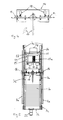
- the elevator 2 comprises a car 3 with car walls 4 and at least one car door 5 on a front side.
- a first guide device 6 is fastened to the elevator shaft.
- the first guide device 6 preferably comprises two first guide profiles 6a, which are arranged on the cabin walls 4 on both sides of the car door 5 in the central cabin area. Guide shoes 3a of the car 3 are guided on the guide profiles 6a.
- a counterweight 7 is guided in a second guide device 8.
- the second guide device 8 preferably comprises two second guide profiles 8a, which are arranged next to the first guide profile 6a in the case of a wall 4 adjoining the car door 5.
- a drive 10 for driving a cable 9, or a steel cable is arranged on the counterweight 7 weight.
- its drive axle 10a extends substantially parallel to a plane through the car wall 4 facing the counterweight 7.
- the drive 10 is gearless and comprises an outer rotor sleeve 11 extending around the drive axle 10a.
- fer sleeve 11 is smaller than the extension of the drive 10 in the direction of the drive axle 10 a.
- the cable 9 is wound with a wrap of at least 180 ° to the outer rotor sleeve 11.
- the outer rotor sleeve 11 comprises outside Rope grooves 11a, which are preferably nitrided.
- the drive 10 is dimensioned such that the diameter of the outer rotor sleeve 11 is smaller than the extension of the drive 10 in the direction of the drive axle 10a.
- the diameter of the outer rotor sleeve 11 is smaller than 320mm and is preferably substantially 240mm. If the drive axle 10a is oriented substantially horizontally, then the extension of the drive 10 in the direction of the drive axle 10a is less than 700 mm, preferably substantially 600 mm. Due to the small diameter of the outer rotor sleeve 11, a steel cable is used as a rope 9, the diameter of a maximum of 8mm, but preferably is substantially 6mm.
- the drive comprises a synchronous electric motor with permanent magnets, wherein the permanent magnets are arranged against the inside of the outer rotor sleeve 11 and the windings for generating the electromagnetic field on the stator within the outer rotor sleeve 11.
- the cable 9 is fixed with both ends at the upper end of the elevator shaft 1, wherein in the figure, only one of the two fasteners 9b - namely on the counterweight 7 - is shown.
- the rope 9 forms a loop 9a in the counterweight 7, then leads via two pulleys 12 at the upper end of the elevator shaft 1 to a loop 9a in the car 3.
- the loop the counterweight 7 may also comprise a pulley arrangement, so that the counterweight 7 only moves over a portion, for example half, of the shaft height.
- the cable loop 9a with the car 3 leads from an upper guide roller 12 via two guide rollers 12 below the car 3 to a fastening 9b, not shown, at the upper end of the elevator shaft 1.
- the cable loop 9a with the counterweight 7 leads from the illustrated attachment 9b over the loop the outer rotor sleeve 11 to an upper pulley 12.
- the diameter of the pulleys 12 is substantially equal to the diameter of the outer rotor sleeve 11 and thus is small. Small diameter pulleys 12 allow the shaft height above the uppermost station and the shaft pit depth below the lowest station to be minimized.
- brake elements 13 are pressed by a pressing device to the outer rotor sleeve 11.
- At least one release electromagnet is used to release the brake elements 13.
- the at least one release electromagnet is connected to a battery via a switching device.
- the battery and the switching device allow the brake elements 13 to be released even in the event of a power failure.
- short-circuit bridges can be switched on, which with the drive supply switched off, brake elements 13 released as well as rotating outer rotor sleeve 11 by the generator effect of the drive 10 to achieve a braking and thereby allow for an emergency release a slow cabin movement.
- a first trailing cable 19 is provided for a supply of the drive 10 and a transmission of control signals between the counterweight 7 and stationary control elements in a control cabinet.
- a second towing cable connects the cab 3 to the control cabinet, thus ensuring the power supply to the cab and the transmission of control and indicating signals between the cab and the controller.
- the trailing cables are formed, for example, as multipolar ribbon cable.
- the control cabinet is preferably located at the lowest station (not shown, because behind the car 3), but possibly at a different station, or even removed from the shaft 1.
- a field-oriented, current-controlled frequency converter with encoder feedback is preferably used, which is preferably arranged in the control cabinet but on the counterweight 7.
- the driving movements of the counterweight 7 lead at the am Counterweight 7 attached components for cooling. It is at least the drive motor of the counterweight 7 cooled by the wind. Although the frequency converter is arranged at the counterweight 7, the frequency converter is also cooled by the airstream. In addition to air cooling, external ventilation may also be installed.
- the drive and, if appropriate, the frequency converter contribute to the mass of the counterweight, so that additional counterbalance weight elements 7a are saved. The entire cost of materials is reduced. If the frequency converter is used directly on the drive, the wiring between the drive and the frequency converter is simplified.
- the elevator requires no machine room for the drive and reduces the material requirements, as well as the manufacturing and assembly costs.
- the counterweight 7 comprises a simply constructed frame 7b, to which the drive 10 and also other components, such as a locking device 14, are fastened to the counterweight 7.
- the drive 10 can be connected via damping elements to the frame 7b. Savings can be made during assembly when the counterweight 7 with the integrated drive 10 is delivered to the construction site as a prefabricated prefabricated component.
- Fig. 3 shows an elevator controller AS, which is connected to a frequency converter FU and a braking device B.
- the brake device B comprises brake elements, which are pressed by a pressing device to the outer rotor sleeve 11 of the electric motor M, and at least one release electromagnet for releasing the brake elements.
- the elevator control AS causes the release of the brake elements and the movement of the motor M via the frequency converter FU.
- a return control RS is equipped with a battery AK and the Braking device B verbun-the.
- the release of the brake device B can be achieved via the battery AK. With this arrangement, a return option is provided in case of power failure.
- the battery AK is charged permanently.
- the brake device B is deblocked, if the battery AK is sufficiently charged. If the charge is insufficient, the elevator in the station remains blocked and enters a fault mode. In fault mode, the car and landing door open and remain open until the fault has been rectified. This prevents the inclusion of persons.
- the main switch is turned off to prevent a dangerous condition when the power returns suddenly. Subsequently, the braking device B is released via the return control RS. Due to the freewheel of the drive 10, the cabin is automatically, in accordance with the loading of the cabin up or down to the nearest stop 1a move. In this emergency operation short-circuiting bridges are turned on, so that braking is achieved by the generator action of the drive 10.
- FIG. 4 shows the locking device 14 with two movable engagement elements 15.
- At least one bracket 16 is attached to the second guide device 8, or to the guide profiles 8a, at least at one maintenance position.
- the locking device 14 is attached to the counterweight 7.
- the at least one movable engagement element 15 for locking the Counterweight 7 are brought into engagement with the at least one console 16.
- a lever 17 of the locking device 14 is actuated.
- the engagement elements 15 are monitored by electromechanical positive contacts 18, wherein the determined positions of the engagement elements 15 are preferably transmitted to the controller AS.
- the car 3 For control and maintenance work on the drive 10, the car 3 is driven to a height et-what under the counterweight 7 and the work can be carried out conveniently from the car roof. For more extensive work the Ge-gen weight 7 is locked with the locking device 14. For safety in the normal operating state and for the safe execution of the maintenance work, the positions of the sliding bolts 15 are monitored by the control AS.
- the described embodiment ensures a simple emergency release and safe maintenance of the drive.
- Fig. 5 shows the frame 7b with two vertical and two horizontal frame parts.
- a foot 22 is arranged, which is associated with a buffer 21 of the elevator shaft 1.
- the housing of the illustrated drive 10 comprises a horizontal mounting plate 23 connected to the frame 7b and end-side end plates 24 which are directed downwards at both ends of the mounting plate 23.
- the end plates 24 are fixed to the stator and are pivotally mounted to the outside.
- An electrical connection device 25 of the drive 10 projects laterally beyond one of the end plates 23.
- the frequency converter is FU. To feed the drive 10 electrical energy from the frequency converter FU to An-circuit device 25th
- the locking device 14 is fastened between the drive 10 and the balance weight elements 7a on the frame 7b.
- To the Guide profiles 8a are brought to Arre-tie-ren of the counterweight 7 at least one console 16 each.
- the guide of the frame 7b on the guide profiles 8a via second guide shoes 7c.
- the frame 7b is preferably supplied with locking device 14, drive 10, frequency converter FU and wiring to the site, making the on-site assembly days is facilitated.
- the frame 7b is supported by the guide shoes 7c on the second guide profiles 8a.
- the rope 9 is inserted with the desired looping in the rope grooves 11a, guided around the guide rollers 12 and secured at both ends at the top in the elevator shaft. Subsequently, the required compensation weight elements 7a are used.
Landscapes
- Engineering & Computer Science (AREA)
- Civil Engineering (AREA)
- Mechanical Engineering (AREA)
- Structural Engineering (AREA)
- Cage And Drive Apparatuses For Elevators (AREA)
Priority Applications (1)
| Application Number | Priority Date | Filing Date | Title |
|---|---|---|---|
| EP06117751.5A EP1882668B1 (fr) | 2006-07-24 | 2006-07-24 | Ascenseur avec moteur placé dans le contre-poids |
Applications Claiming Priority (1)
| Application Number | Priority Date | Filing Date | Title |
|---|---|---|---|
| EP06117751.5A EP1882668B1 (fr) | 2006-07-24 | 2006-07-24 | Ascenseur avec moteur placé dans le contre-poids |
Publications (2)
| Publication Number | Publication Date |
|---|---|
| EP1882668A1 true EP1882668A1 (fr) | 2008-01-30 |
| EP1882668B1 EP1882668B1 (fr) | 2023-08-30 |
Family
ID=38089164
Family Applications (1)
| Application Number | Title | Priority Date | Filing Date |
|---|---|---|---|
| EP06117751.5A Active EP1882668B1 (fr) | 2006-07-24 | 2006-07-24 | Ascenseur avec moteur placé dans le contre-poids |
Country Status (1)
| Country | Link |
|---|---|
| EP (1) | EP1882668B1 (fr) |
Cited By (4)
| Publication number | Priority date | Publication date | Assignee | Title |
|---|---|---|---|---|
| EP2174903A3 (fr) * | 2008-10-12 | 2010-04-28 | H. Henseler AG | Entraînement pour une cabine d'ascenseur, maintenable à partir de la cabine |
| WO2010054570A1 (fr) * | 2008-11-17 | 2010-05-20 | Lv Anwen | Dispositif de levage |
| EP2497739A1 (fr) | 2011-03-10 | 2012-09-12 | Hansruedi Diethelm | Ascenseur |
| CN112158707A (zh) * | 2020-09-28 | 2021-01-01 | 扬州伟铧电梯有限公司 | 轿厢驱动式升降电梯 |
Citations (7)
| Publication number | Priority date | Publication date | Assignee | Title |
|---|---|---|---|---|
| FR2505574A1 (fr) * | 1981-05-07 | 1982-11-12 | Elevator Gmbh | Moteur a cage d'ecureuil avec convertisseur commande de frequence |
| EP0606875A1 (fr) * | 1993-01-11 | 1994-07-20 | Kone Oy | Moteur d'ascenseur monté dans le contrepoids |
| JPH07117957A (ja) * | 1993-10-28 | 1995-05-09 | Mitsubishi Electric Corp | エレベーター装置 |
| EP0878430A2 (fr) * | 1997-05-16 | 1998-11-18 | Baumüller Nürnberg Gmbh | Dispositif de levage, en particuler ascenseur, avec un moteur électrique et utilisation du moteur électrique |
| EP1085643A2 (fr) * | 1999-09-13 | 2001-03-21 | Cobianchi Liftteile Ag | Moteur synchrone du type à aimants permanents pour treuils d'entraínement d'ascenseurs |
| JP2003104665A (ja) * | 2001-09-28 | 2003-04-09 | Toshiba Elevator Co Ltd | エレベータ |
| EP1432104A2 (fr) * | 2002-12-16 | 2004-06-23 | ebm-papst St. Georgen GmbH & Co. KG | Moteur à rotor extérieur avec support de palier fixé |
-
2006
- 2006-07-24 EP EP06117751.5A patent/EP1882668B1/fr active Active
Patent Citations (7)
| Publication number | Priority date | Publication date | Assignee | Title |
|---|---|---|---|---|
| FR2505574A1 (fr) * | 1981-05-07 | 1982-11-12 | Elevator Gmbh | Moteur a cage d'ecureuil avec convertisseur commande de frequence |
| EP0606875A1 (fr) * | 1993-01-11 | 1994-07-20 | Kone Oy | Moteur d'ascenseur monté dans le contrepoids |
| JPH07117957A (ja) * | 1993-10-28 | 1995-05-09 | Mitsubishi Electric Corp | エレベーター装置 |
| EP0878430A2 (fr) * | 1997-05-16 | 1998-11-18 | Baumüller Nürnberg Gmbh | Dispositif de levage, en particuler ascenseur, avec un moteur électrique et utilisation du moteur électrique |
| EP1085643A2 (fr) * | 1999-09-13 | 2001-03-21 | Cobianchi Liftteile Ag | Moteur synchrone du type à aimants permanents pour treuils d'entraínement d'ascenseurs |
| JP2003104665A (ja) * | 2001-09-28 | 2003-04-09 | Toshiba Elevator Co Ltd | エレベータ |
| EP1432104A2 (fr) * | 2002-12-16 | 2004-06-23 | ebm-papst St. Georgen GmbH & Co. KG | Moteur à rotor extérieur avec support de palier fixé |
Cited By (4)
| Publication number | Priority date | Publication date | Assignee | Title |
|---|---|---|---|---|
| EP2174903A3 (fr) * | 2008-10-12 | 2010-04-28 | H. Henseler AG | Entraînement pour une cabine d'ascenseur, maintenable à partir de la cabine |
| WO2010054570A1 (fr) * | 2008-11-17 | 2010-05-20 | Lv Anwen | Dispositif de levage |
| EP2497739A1 (fr) | 2011-03-10 | 2012-09-12 | Hansruedi Diethelm | Ascenseur |
| CN112158707A (zh) * | 2020-09-28 | 2021-01-01 | 扬州伟铧电梯有限公司 | 轿厢驱动式升降电梯 |
Also Published As
| Publication number | Publication date |
|---|---|
| EP1882668B1 (fr) | 2023-08-30 |
Similar Documents
| Publication | Publication Date | Title |
|---|---|---|
| EP1305249B1 (fr) | Cabine d'ascenseur disposant d'une machine d'entrainement de poulie motrice integree | |
| EP3807205B1 (fr) | Procédé de construction d'une installation d'ascenseur | |
| WO2011054833A1 (fr) | Ascenseur | |
| EP4077193B1 (fr) | Procédé de centrage d'une cabine d'ascenseur | |
| EP1118575A2 (fr) | Installation d'ascenseur avec unité de levage positionnée dans la cage | |
| EP2709941B1 (fr) | Système d'ascenseur | |
| EP1882668B1 (fr) | Ascenseur avec moteur placé dans le contre-poids | |
| EP1069068B1 (fr) | Entraînement compact pour un ascenseur | |
| EP0926093B1 (fr) | Ascenseur, en particulier ascenseur à poulie | |
| EP1566358A1 (fr) | Ascenseur à poulie de traction sans machinerie | |
| EP4392637A1 (fr) | Ensemble d'entraînement pour une porte relevable avec un moteur tubulaire sur un arbre statique, porte relevable, et procédé de fonctionnement d'une porte relevable | |
| EP3153454B1 (fr) | Verrouillage de porte | |
| DE102008049379A1 (de) | Notbefreiungssystem für Aufzüge | |
| DE102017004719A1 (de) | Vorrichtung für einen gesicherten Bereich in einem Aufzugschacht | |
| WO2020164965A1 (fr) | Système d'ascenseur | |
| DE19902853C2 (de) | Personen-Seilaufzug | |
| EP2303751B1 (fr) | Installation d'ascenseur dotée d'un contrepoids automatique | |
| WO2007143871A2 (fr) | Installation d'ascenseur | |
| DE102011118544A1 (de) | Hilfsantrieb für Fahrkörbe von Aufzugsanlagen | |
| EP2500310A1 (fr) | Installation d'ascenseur | |
| DE102007016815A1 (de) | Schiebetürsystem | |
| DE3722305A1 (de) | Aufzug mit linearmotor | |
| EP2960197A1 (fr) | Enroulement de secours pour systemes electriques de protection contre le soleil et l'eblouissement | |
| DE10357035A1 (de) | Aufzuganlage mit schwenkbarer Fahrkorbschürze | |
| EP1547961A1 (fr) | Mécanisme d'entraínement pour ascenseur |
Legal Events
| Date | Code | Title | Description |
|---|---|---|---|
| PUAI | Public reference made under article 153(3) epc to a published international application that has entered the european phase |
Free format text: ORIGINAL CODE: 0009012 |
|
| AK | Designated contracting states |
Kind code of ref document: A1 Designated state(s): AT BE BG CH CY CZ DE DK EE ES FI FR GB GR HU IE IS IT LI LT LU LV MC NL PL PT RO SE SI SK TR |
|
| AX | Request for extension of the european patent |
Extension state: AL BA HR MK YU |
|
| 17P | Request for examination filed |
Effective date: 20080514 |
|
| 17Q | First examination report despatched |
Effective date: 20080711 |
|
| TPAC | Observations filed by third parties |
Free format text: ORIGINAL CODE: EPIDOSNTIPA |
|
| AKX | Designation fees paid |
Designated state(s): AT BE BG CH CY CZ DE DK EE ES FI FR GB GR HU IE IS IT LI LT LU LV MC NL PL PT RO SE SI SK TR |
|
| STAA | Information on the status of an ep patent application or granted ep patent |
Free format text: STATUS: EXAMINATION IS IN PROGRESS |
|
| GRAP | Despatch of communication of intention to grant a patent |
Free format text: ORIGINAL CODE: EPIDOSNIGR1 |
|
| STAA | Information on the status of an ep patent application or granted ep patent |
Free format text: STATUS: GRANT OF PATENT IS INTENDED |
|
| INTG | Intention to grant announced |
Effective date: 20220714 |
|
| GRAJ | Information related to disapproval of communication of intention to grant by the applicant or resumption of examination proceedings by the epo deleted |
Free format text: ORIGINAL CODE: EPIDOSDIGR1 |
|
| STAA | Information on the status of an ep patent application or granted ep patent |
Free format text: STATUS: EXAMINATION IS IN PROGRESS |
|
| INTC | Intention to grant announced (deleted) | ||
| GRAP | Despatch of communication of intention to grant a patent |
Free format text: ORIGINAL CODE: EPIDOSNIGR1 |
|
| STAA | Information on the status of an ep patent application or granted ep patent |
Free format text: STATUS: GRANT OF PATENT IS INTENDED |
|
| INTG | Intention to grant announced |
Effective date: 20230216 |
|
| GRAS | Grant fee paid |
Free format text: ORIGINAL CODE: EPIDOSNIGR3 |
|
| GRAA | (expected) grant |
Free format text: ORIGINAL CODE: 0009210 |
|
| STAA | Information on the status of an ep patent application or granted ep patent |
Free format text: STATUS: THE PATENT HAS BEEN GRANTED |
|
| AK | Designated contracting states |
Kind code of ref document: B1 Designated state(s): AT BE BG CH CY CZ DE DK EE ES FI FR GB GR HU IE IS IT LI LT LU LV MC NL PL PT RO SE SI SK TR |
|
| REG | Reference to a national code |
Ref country code: GB Ref legal event code: FG4D Free format text: NOT ENGLISH |
|
| REG | Reference to a national code |
Ref country code: CH Ref legal event code: EP |
|
| P01 | Opt-out of the competence of the unified patent court (upc) registered |
Effective date: 20230804 |
|
| REG | Reference to a national code |
Ref country code: DE Ref legal event code: R096 Ref document number: 502006016496 Country of ref document: DE |
|
| REG | Reference to a national code |
Ref country code: IE Ref legal event code: FG4D Free format text: LANGUAGE OF EP DOCUMENT: GERMAN |
|
| REG | Reference to a national code |
Ref country code: LT Ref legal event code: MG9D |
|
| REG | Reference to a national code |
Ref country code: NL Ref legal event code: MP Effective date: 20230830 |
|
| PG25 | Lapsed in a contracting state [announced via postgrant information from national office to epo] |
Ref country code: GR Free format text: LAPSE BECAUSE OF FAILURE TO SUBMIT A TRANSLATION OF THE DESCRIPTION OR TO PAY THE FEE WITHIN THE PRESCRIBED TIME-LIMIT Effective date: 20231201 |
|
| PG25 | Lapsed in a contracting state [announced via postgrant information from national office to epo] |
Ref country code: IS Free format text: LAPSE BECAUSE OF FAILURE TO SUBMIT A TRANSLATION OF THE DESCRIPTION OR TO PAY THE FEE WITHIN THE PRESCRIBED TIME-LIMIT Effective date: 20231230 |
|
| PG25 | Lapsed in a contracting state [announced via postgrant information from national office to epo] |
Ref country code: SE Free format text: LAPSE BECAUSE OF FAILURE TO SUBMIT A TRANSLATION OF THE DESCRIPTION OR TO PAY THE FEE WITHIN THE PRESCRIBED TIME-LIMIT Effective date: 20230830 Ref country code: LV Free format text: LAPSE BECAUSE OF FAILURE TO SUBMIT A TRANSLATION OF THE DESCRIPTION OR TO PAY THE FEE WITHIN THE PRESCRIBED TIME-LIMIT Effective date: 20230830 Ref country code: LT Free format text: LAPSE BECAUSE OF FAILURE TO SUBMIT A TRANSLATION OF THE DESCRIPTION OR TO PAY THE FEE WITHIN THE PRESCRIBED TIME-LIMIT Effective date: 20230830 Ref country code: IS Free format text: LAPSE BECAUSE OF FAILURE TO SUBMIT A TRANSLATION OF THE DESCRIPTION OR TO PAY THE FEE WITHIN THE PRESCRIBED TIME-LIMIT Effective date: 20231230 Ref country code: GR Free format text: LAPSE BECAUSE OF FAILURE TO SUBMIT A TRANSLATION OF THE DESCRIPTION OR TO PAY THE FEE WITHIN THE PRESCRIBED TIME-LIMIT Effective date: 20231201 Ref country code: FI Free format text: LAPSE BECAUSE OF FAILURE TO SUBMIT A TRANSLATION OF THE DESCRIPTION OR TO PAY THE FEE WITHIN THE PRESCRIBED TIME-LIMIT Effective date: 20230830 |
|
| PG25 | Lapsed in a contracting state [announced via postgrant information from national office to epo] |
Ref country code: PL Free format text: LAPSE BECAUSE OF FAILURE TO SUBMIT A TRANSLATION OF THE DESCRIPTION OR TO PAY THE FEE WITHIN THE PRESCRIBED TIME-LIMIT Effective date: 20230830 Ref country code: NL Free format text: LAPSE BECAUSE OF FAILURE TO SUBMIT A TRANSLATION OF THE DESCRIPTION OR TO PAY THE FEE WITHIN THE PRESCRIBED TIME-LIMIT Effective date: 20230830 |
|
| PG25 | Lapsed in a contracting state [announced via postgrant information from national office to epo] |
Ref country code: ES Free format text: LAPSE BECAUSE OF FAILURE TO SUBMIT A TRANSLATION OF THE DESCRIPTION OR TO PAY THE FEE WITHIN THE PRESCRIBED TIME-LIMIT Effective date: 20230830 |
|
| PG25 | Lapsed in a contracting state [announced via postgrant information from national office to epo] |
Ref country code: RO Free format text: LAPSE BECAUSE OF FAILURE TO SUBMIT A TRANSLATION OF THE DESCRIPTION OR TO PAY THE FEE WITHIN THE PRESCRIBED TIME-LIMIT Effective date: 20230830 Ref country code: ES Free format text: LAPSE BECAUSE OF FAILURE TO SUBMIT A TRANSLATION OF THE DESCRIPTION OR TO PAY THE FEE WITHIN THE PRESCRIBED TIME-LIMIT Effective date: 20230830 Ref country code: EE Free format text: LAPSE BECAUSE OF FAILURE TO SUBMIT A TRANSLATION OF THE DESCRIPTION OR TO PAY THE FEE WITHIN THE PRESCRIBED TIME-LIMIT Effective date: 20230830 Ref country code: DK Free format text: LAPSE BECAUSE OF FAILURE TO SUBMIT A TRANSLATION OF THE DESCRIPTION OR TO PAY THE FEE WITHIN THE PRESCRIBED TIME-LIMIT Effective date: 20230830 Ref country code: CZ Free format text: LAPSE BECAUSE OF FAILURE TO SUBMIT A TRANSLATION OF THE DESCRIPTION OR TO PAY THE FEE WITHIN THE PRESCRIBED TIME-LIMIT Effective date: 20230830 Ref country code: SK Free format text: LAPSE BECAUSE OF FAILURE TO SUBMIT A TRANSLATION OF THE DESCRIPTION OR TO PAY THE FEE WITHIN THE PRESCRIBED TIME-LIMIT Effective date: 20230830 Ref country code: PT Free format text: LAPSE BECAUSE OF FAILURE TO SUBMIT A TRANSLATION OF THE DESCRIPTION OR TO PAY THE FEE WITHIN THE PRESCRIBED TIME-LIMIT Effective date: 20240102 |
|
| REG | Reference to a national code |
Ref country code: DE Ref legal event code: R097 Ref document number: 502006016496 Country of ref document: DE |
|
| PLBE | No opposition filed within time limit |
Free format text: ORIGINAL CODE: 0009261 |
|
| STAA | Information on the status of an ep patent application or granted ep patent |
Free format text: STATUS: NO OPPOSITION FILED WITHIN TIME LIMIT |
|
| PG25 | Lapsed in a contracting state [announced via postgrant information from national office to epo] |
Ref country code: SI Free format text: LAPSE BECAUSE OF FAILURE TO SUBMIT A TRANSLATION OF THE DESCRIPTION OR TO PAY THE FEE WITHIN THE PRESCRIBED TIME-LIMIT Effective date: 20230830 |
|
| 26N | No opposition filed |
Effective date: 20240603 |
|
| PG25 | Lapsed in a contracting state [announced via postgrant information from national office to epo] |
Ref country code: BG Free format text: LAPSE BECAUSE OF FAILURE TO SUBMIT A TRANSLATION OF THE DESCRIPTION OR TO PAY THE FEE WITHIN THE PRESCRIBED TIME-LIMIT Effective date: 20230830 |
|
| PG25 | Lapsed in a contracting state [announced via postgrant information from national office to epo] |
Ref country code: BG Free format text: LAPSE BECAUSE OF FAILURE TO SUBMIT A TRANSLATION OF THE DESCRIPTION OR TO PAY THE FEE WITHIN THE PRESCRIBED TIME-LIMIT Effective date: 20230830 |
|
| PG25 | Lapsed in a contracting state [announced via postgrant information from national office to epo] |
Ref country code: MC Free format text: LAPSE BECAUSE OF FAILURE TO SUBMIT A TRANSLATION OF THE DESCRIPTION OR TO PAY THE FEE WITHIN THE PRESCRIBED TIME-LIMIT Effective date: 20230830 |
|
| PG25 | Lapsed in a contracting state [announced via postgrant information from national office to epo] |
Ref country code: LU Free format text: LAPSE BECAUSE OF NON-PAYMENT OF DUE FEES Effective date: 20240724 |
|
| GBPC | Gb: european patent ceased through non-payment of renewal fee |
Effective date: 20240724 |
|
| PG25 | Lapsed in a contracting state [announced via postgrant information from national office to epo] |
Ref country code: LU Free format text: LAPSE BECAUSE OF NON-PAYMENT OF DUE FEES Effective date: 20240724 |
|
| PG25 | Lapsed in a contracting state [announced via postgrant information from national office to epo] |
Ref country code: BE Free format text: LAPSE BECAUSE OF NON-PAYMENT OF DUE FEES Effective date: 20240731 |
|
| PG25 | Lapsed in a contracting state [announced via postgrant information from national office to epo] |
Ref country code: GB Free format text: LAPSE BECAUSE OF NON-PAYMENT OF DUE FEES Effective date: 20240724 |
|
| REG | Reference to a national code |
Ref country code: BE Ref legal event code: MM Effective date: 20240731 |
|
| PG25 | Lapsed in a contracting state [announced via postgrant information from national office to epo] |
Ref country code: IE Free format text: LAPSE BECAUSE OF NON-PAYMENT OF DUE FEES Effective date: 20240724 |
|
| PGFP | Annual fee paid to national office [announced via postgrant information from national office to epo] |
Ref country code: DE Payment date: 20250722 Year of fee payment: 20 |
|
| PGFP | Annual fee paid to national office [announced via postgrant information from national office to epo] |
Ref country code: IT Payment date: 20250731 Year of fee payment: 20 |
|
| PGFP | Annual fee paid to national office [announced via postgrant information from national office to epo] |
Ref country code: FR Payment date: 20250723 Year of fee payment: 20 Ref country code: AT Payment date: 20250721 Year of fee payment: 20 |
|
| PGFP | Annual fee paid to national office [announced via postgrant information from national office to epo] |
Ref country code: CH Payment date: 20250801 Year of fee payment: 20 |
|
| PG25 | Lapsed in a contracting state [announced via postgrant information from national office to epo] |
Ref country code: CY Free format text: LAPSE BECAUSE OF FAILURE TO SUBMIT A TRANSLATION OF THE DESCRIPTION OR TO PAY THE FEE WITHIN THE PRESCRIBED TIME-LIMIT; INVALID AB INITIO Effective date: 20060724 |
|
| PG25 | Lapsed in a contracting state [announced via postgrant information from national office to epo] |
Ref country code: HU Free format text: LAPSE BECAUSE OF FAILURE TO SUBMIT A TRANSLATION OF THE DESCRIPTION OR TO PAY THE FEE WITHIN THE PRESCRIBED TIME-LIMIT; INVALID AB INITIO Effective date: 20060724 |