EP1882802A2 - Method for safe braking of a gate and device for implementing the method - Google Patents
Method for safe braking of a gate and device for implementing the method Download PDFInfo
- Publication number
- EP1882802A2 EP1882802A2 EP07111601A EP07111601A EP1882802A2 EP 1882802 A2 EP1882802 A2 EP 1882802A2 EP 07111601 A EP07111601 A EP 07111601A EP 07111601 A EP07111601 A EP 07111601A EP 1882802 A2 EP1882802 A2 EP 1882802A2
- Authority
- EP
- European Patent Office
- Prior art keywords
- braking
- control device
- gate
- door
- frequency converter
- Prior art date
- Legal status (The legal status is an assumption and is not a legal conclusion. Google has not performed a legal analysis and makes no representation as to the accuracy of the status listed.)
- Granted
Links
Images

Classifications
-
- G—PHYSICS
- G05—CONTROLLING; REGULATING
- G05B—CONTROL OR REGULATING SYSTEMS IN GENERAL; FUNCTIONAL ELEMENTS OF SUCH SYSTEMS; MONITORING OR TESTING ARRANGEMENTS FOR SUCH SYSTEMS OR ELEMENTS
- G05B19/00—Program-control systems
- G05B19/02—Program-control systems electric
- G05B19/18—Numerical control [NC], i.e. automatically operating machines, in particular machine tools, e.g. in a manufacturing environment, so as to execute positioning, movement or co-ordinated operations by means of program data in numerical form
- G05B19/416—Numerical control [NC], i.e. automatically operating machines, in particular machine tools, e.g. in a manufacturing environment, so as to execute positioning, movement or co-ordinated operations by means of program data in numerical form characterised by control of velocity, acceleration or deceleration
-
- E—FIXED CONSTRUCTIONS
- E05—LOCKS; KEYS; WINDOW OR DOOR FITTINGS; SAFES
- E05F—DEVICES FOR MOVING WINGS INTO OPEN OR CLOSED POSITION; CHECKS FOR WINGS; WING FITTINGS NOT OTHERWISE PROVIDED FOR, CONCERNED WITH THE FUNCTIONING OF THE WING
- E05F15/00—Power-operated mechanisms for wings
- E05F15/40—Safety devices, e.g. detection of obstructions or end positions
-
- E—FIXED CONSTRUCTIONS
- E06—DOORS, WINDOWS, SHUTTERS, OR ROLLER BLINDS IN GENERAL; LADDERS
- E06B—FIXED OR MOVABLE CLOSURES FOR OPENINGS IN BUILDINGS, VEHICLES, FENCES OR LIKE ENCLOSURES IN GENERAL, e.g. DOORS, WINDOWS, BLINDS, GATES
- E06B9/00—Screening or protective devices for wall or similar openings, with or without operating or securing mechanisms; Closures of similar construction
- E06B9/56—Operating, guiding or securing devices or arrangements for roll-type closures; Spring drums; Tape drums; Counterweighting arrangements therefor
- E06B9/80—Safety measures against dropping or unauthorised opening; Braking or immobilising devices; Devices for limiting unrolling
- E06B9/82—Safety measures against dropping or unauthorised opening; Braking or immobilising devices; Devices for limiting unrolling automatic
- E06B9/84—Safety measures against dropping or unauthorised opening; Braking or immobilising devices; Devices for limiting unrolling automatic against dropping
-
- E—FIXED CONSTRUCTIONS
- E05—LOCKS; KEYS; WINDOW OR DOOR FITTINGS; SAFES
- E05D—HINGES OR SUSPENSION DEVICES FOR DOORS, WINDOWS OR WINGS
- E05D13/00—Accessories for sliding or lifting wings, e.g. pulleys, safety catches
- E05D13/003—Anti-dropping devices
-
- E—FIXED CONSTRUCTIONS
- E05—LOCKS; KEYS; WINDOW OR DOOR FITTINGS; SAFES
- E05F—DEVICES FOR MOVING WINGS INTO OPEN OR CLOSED POSITION; CHECKS FOR WINGS; WING FITTINGS NOT OTHERWISE PROVIDED FOR, CONCERNED WITH THE FUNCTIONING OF THE WING
- E05F15/00—Power-operated mechanisms for wings
-
- E—FIXED CONSTRUCTIONS
- E05—LOCKS; KEYS; WINDOW OR DOOR FITTINGS; SAFES
- E05F—DEVICES FOR MOVING WINGS INTO OPEN OR CLOSED POSITION; CHECKS FOR WINGS; WING FITTINGS NOT OTHERWISE PROVIDED FOR, CONCERNED WITH THE FUNCTIONING OF THE WING
- E05F15/00—Power-operated mechanisms for wings
- E05F15/60—Power-operated mechanisms for wings using electrical actuators
- E05F15/603—Power-operated mechanisms for wings using electrical actuators using rotary electromotors
- E05F15/665—Power-operated mechanisms for wings using electrical actuators using rotary electromotors for vertically-sliding wings
- E05F15/668—Power-operated mechanisms for wings using electrical actuators using rotary electromotors for vertically-sliding wings for overhead wings
-
- E—FIXED CONSTRUCTIONS
- E05—LOCKS; KEYS; WINDOW OR DOOR FITTINGS; SAFES
- E05F—DEVICES FOR MOVING WINGS INTO OPEN OR CLOSED POSITION; CHECKS FOR WINGS; WING FITTINGS NOT OTHERWISE PROVIDED FOR, CONCERNED WITH THE FUNCTIONING OF THE WING
- E05F15/00—Power-operated mechanisms for wings
- E05F15/70—Power-operated mechanisms for wings with automatic actuation
- E05F15/72—Power-operated mechanisms for wings with automatic actuation responsive to emergency conditions, e.g. fire
-
- E—FIXED CONSTRUCTIONS
- E05—LOCKS; KEYS; WINDOW OR DOOR FITTINGS; SAFES
- E05Y—INDEXING SCHEME ASSOCIATED WITH SUBCLASSES E05D AND E05F, RELATING TO CONSTRUCTION ELEMENTS, ELECTRIC CONTROL, POWER SUPPLY, POWER SIGNAL OR TRANSMISSION, USER INTERFACES, MOUNTING OR COUPLING, DETAILS, ACCESSORIES, AUXILIARY OPERATIONS NOT OTHERWISE PROVIDED FOR, APPLICATION THEREOF
- E05Y2201/00—Constructional elements; Accessories therefor
- E05Y2201/20—Brakes; Disengaging means; Holders; Stops; Valves; Accessories therefor
- E05Y2201/21—Brakes
-
- E—FIXED CONSTRUCTIONS
- E05—LOCKS; KEYS; WINDOW OR DOOR FITTINGS; SAFES
- E05Y—INDEXING SCHEME ASSOCIATED WITH SUBCLASSES E05D AND E05F, RELATING TO CONSTRUCTION ELEMENTS, ELECTRIC CONTROL, POWER SUPPLY, POWER SIGNAL OR TRANSMISSION, USER INTERFACES, MOUNTING OR COUPLING, DETAILS, ACCESSORIES, AUXILIARY OPERATIONS NOT OTHERWISE PROVIDED FOR, APPLICATION THEREOF
- E05Y2201/00—Constructional elements; Accessories therefor
- E05Y2201/20—Brakes; Disengaging means; Holders; Stops; Valves; Accessories therefor
- E05Y2201/23—Actuation thereof
- E05Y2201/246—Actuation thereof by auxiliary motors, magnets, springs or weights
-
- E—FIXED CONSTRUCTIONS
- E05—LOCKS; KEYS; WINDOW OR DOOR FITTINGS; SAFES
- E05Y—INDEXING SCHEME ASSOCIATED WITH SUBCLASSES E05D AND E05F, RELATING TO CONSTRUCTION ELEMENTS, ELECTRIC CONTROL, POWER SUPPLY, POWER SIGNAL OR TRANSMISSION, USER INTERFACES, MOUNTING OR COUPLING, DETAILS, ACCESSORIES, AUXILIARY OPERATIONS NOT OTHERWISE PROVIDED FOR, APPLICATION THEREOF
- E05Y2201/00—Constructional elements; Accessories therefor
- E05Y2201/20—Brakes; Disengaging means; Holders; Stops; Valves; Accessories therefor
- E05Y2201/252—Type of friction
- E05Y2201/26—Mechanical friction
-
- E—FIXED CONSTRUCTIONS
- E05—LOCKS; KEYS; WINDOW OR DOOR FITTINGS; SAFES
- E05Y—INDEXING SCHEME ASSOCIATED WITH SUBCLASSES E05D AND E05F, RELATING TO CONSTRUCTION ELEMENTS, ELECTRIC CONTROL, POWER SUPPLY, POWER SIGNAL OR TRANSMISSION, USER INTERFACES, MOUNTING OR COUPLING, DETAILS, ACCESSORIES, AUXILIARY OPERATIONS NOT OTHERWISE PROVIDED FOR, APPLICATION THEREOF
- E05Y2201/00—Constructional elements; Accessories therefor
- E05Y2201/20—Brakes; Disengaging means; Holders; Stops; Valves; Accessories therefor
- E05Y2201/262—Type of motion, e.g. braking
- E05Y2201/266—Type of motion, e.g. braking rotary
-
- E—FIXED CONSTRUCTIONS
- E05—LOCKS; KEYS; WINDOW OR DOOR FITTINGS; SAFES
- E05Y—INDEXING SCHEME ASSOCIATED WITH SUBCLASSES E05D AND E05F, RELATING TO CONSTRUCTION ELEMENTS, ELECTRIC CONTROL, POWER SUPPLY, POWER SIGNAL OR TRANSMISSION, USER INTERFACES, MOUNTING OR COUPLING, DETAILS, ACCESSORIES, AUXILIARY OPERATIONS NOT OTHERWISE PROVIDED FOR, APPLICATION THEREOF
- E05Y2201/00—Constructional elements; Accessories therefor
- E05Y2201/40—Motors; Magnets; Springs; Weights; Accessories therefor
- E05Y2201/43—Motors
- E05Y2201/434—Electromotors; Details thereof
-
- E—FIXED CONSTRUCTIONS
- E05—LOCKS; KEYS; WINDOW OR DOOR FITTINGS; SAFES
- E05Y—INDEXING SCHEME ASSOCIATED WITH SUBCLASSES E05D AND E05F, RELATING TO CONSTRUCTION ELEMENTS, ELECTRIC CONTROL, POWER SUPPLY, POWER SIGNAL OR TRANSMISSION, USER INTERFACES, MOUNTING OR COUPLING, DETAILS, ACCESSORIES, AUXILIARY OPERATIONS NOT OTHERWISE PROVIDED FOR, APPLICATION THEREOF
- E05Y2201/00—Constructional elements; Accessories therefor
- E05Y2201/40—Motors; Magnets; Springs; Weights; Accessories therefor
- E05Y2201/46—Magnets
- E05Y2201/462—Electromagnets
-
- E—FIXED CONSTRUCTIONS
- E05—LOCKS; KEYS; WINDOW OR DOOR FITTINGS; SAFES
- E05Y—INDEXING SCHEME ASSOCIATED WITH SUBCLASSES E05D AND E05F, RELATING TO CONSTRUCTION ELEMENTS, ELECTRIC CONTROL, POWER SUPPLY, POWER SIGNAL OR TRANSMISSION, USER INTERFACES, MOUNTING OR COUPLING, DETAILS, ACCESSORIES, AUXILIARY OPERATIONS NOT OTHERWISE PROVIDED FOR, APPLICATION THEREOF
- E05Y2400/00—Electronic control; Electrical power; Power supply; Power or signal transmission; User interfaces
- E05Y2400/10—Electronic control
- E05Y2400/30—Electronic control of motors
- E05Y2400/302—Electronic control of motors during electric motor braking
-
- E—FIXED CONSTRUCTIONS
- E05—LOCKS; KEYS; WINDOW OR DOOR FITTINGS; SAFES
- E05Y—INDEXING SCHEME ASSOCIATED WITH SUBCLASSES E05D AND E05F, RELATING TO CONSTRUCTION ELEMENTS, ELECTRIC CONTROL, POWER SUPPLY, POWER SIGNAL OR TRANSMISSION, USER INTERFACES, MOUNTING OR COUPLING, DETAILS, ACCESSORIES, AUXILIARY OPERATIONS NOT OTHERWISE PROVIDED FOR, APPLICATION THEREOF
- E05Y2400/00—Electronic control; Electrical power; Power supply; Power or signal transmission; User interfaces
- E05Y2400/10—Electronic control
- E05Y2400/36—Speed control, detection or monitoring
-
- E—FIXED CONSTRUCTIONS
- E05—LOCKS; KEYS; WINDOW OR DOOR FITTINGS; SAFES
- E05Y—INDEXING SCHEME ASSOCIATED WITH SUBCLASSES E05D AND E05F, RELATING TO CONSTRUCTION ELEMENTS, ELECTRIC CONTROL, POWER SUPPLY, POWER SIGNAL OR TRANSMISSION, USER INTERFACES, MOUNTING OR COUPLING, DETAILS, ACCESSORIES, AUXILIARY OPERATIONS NOT OTHERWISE PROVIDED FOR, APPLICATION THEREOF
- E05Y2400/00—Electronic control; Electrical power; Power supply; Power or signal transmission; User interfaces
- E05Y2400/10—Electronic control
- E05Y2400/50—Fault detection
- E05Y2400/506—Fault detection of counterbalance
-
- E—FIXED CONSTRUCTIONS
- E05—LOCKS; KEYS; WINDOW OR DOOR FITTINGS; SAFES
- E05Y—INDEXING SCHEME ASSOCIATED WITH SUBCLASSES E05D AND E05F, RELATING TO CONSTRUCTION ELEMENTS, ELECTRIC CONTROL, POWER SUPPLY, POWER SIGNAL OR TRANSMISSION, USER INTERFACES, MOUNTING OR COUPLING, DETAILS, ACCESSORIES, AUXILIARY OPERATIONS NOT OTHERWISE PROVIDED FOR, APPLICATION THEREOF
- E05Y2400/00—Electronic control; Electrical power; Power supply; Power or signal transmission; User interfaces
- E05Y2400/10—Electronic control
- E05Y2400/50—Fault detection
- E05Y2400/51—Fault detection of position, of back drive
-
- E—FIXED CONSTRUCTIONS
- E05—LOCKS; KEYS; WINDOW OR DOOR FITTINGS; SAFES
- E05Y—INDEXING SCHEME ASSOCIATED WITH SUBCLASSES E05D AND E05F, RELATING TO CONSTRUCTION ELEMENTS, ELECTRIC CONTROL, POWER SUPPLY, POWER SIGNAL OR TRANSMISSION, USER INTERFACES, MOUNTING OR COUPLING, DETAILS, ACCESSORIES, AUXILIARY OPERATIONS NOT OTHERWISE PROVIDED FOR, APPLICATION THEREOF
- E05Y2400/00—Electronic control; Electrical power; Power supply; Power or signal transmission; User interfaces
- E05Y2400/10—Electronic control
- E05Y2400/50—Fault detection
- E05Y2400/514—Fault detection of speed
-
- E—FIXED CONSTRUCTIONS
- E05—LOCKS; KEYS; WINDOW OR DOOR FITTINGS; SAFES
- E05Y—INDEXING SCHEME ASSOCIATED WITH SUBCLASSES E05D AND E05F, RELATING TO CONSTRUCTION ELEMENTS, ELECTRIC CONTROL, POWER SUPPLY, POWER SIGNAL OR TRANSMISSION, USER INTERFACES, MOUNTING OR COUPLING, DETAILS, ACCESSORIES, AUXILIARY OPERATIONS NOT OTHERWISE PROVIDED FOR, APPLICATION THEREOF
- E05Y2400/00—Electronic control; Electrical power; Power supply; Power or signal transmission; User interfaces
- E05Y2400/10—Electronic control
- E05Y2400/52—Safety arrangements associated with the wing motor
- E05Y2400/53—Wing impact prevention or reduction
- E05Y2400/532—Emergency braking or blocking
-
- E—FIXED CONSTRUCTIONS
- E05—LOCKS; KEYS; WINDOW OR DOOR FITTINGS; SAFES
- E05Y—INDEXING SCHEME ASSOCIATED WITH SUBCLASSES E05D AND E05F, RELATING TO CONSTRUCTION ELEMENTS, ELECTRIC CONTROL, POWER SUPPLY, POWER SIGNAL OR TRANSMISSION, USER INTERFACES, MOUNTING OR COUPLING, DETAILS, ACCESSORIES, AUXILIARY OPERATIONS NOT OTHERWISE PROVIDED FOR, APPLICATION THEREOF
- E05Y2400/00—Electronic control; Electrical power; Power supply; Power or signal transmission; User interfaces
- E05Y2400/80—User interfaces
- E05Y2400/81—Feedback to user, e.g. tactile
- E05Y2400/818—Visual
- E05Y2400/822—Light emitters, e.g. light emitting diodes [LED]
-
- E—FIXED CONSTRUCTIONS
- E05—LOCKS; KEYS; WINDOW OR DOOR FITTINGS; SAFES
- E05Y—INDEXING SCHEME ASSOCIATED WITH SUBCLASSES E05D AND E05F, RELATING TO CONSTRUCTION ELEMENTS, ELECTRIC CONTROL, POWER SUPPLY, POWER SIGNAL OR TRANSMISSION, USER INTERFACES, MOUNTING OR COUPLING, DETAILS, ACCESSORIES, AUXILIARY OPERATIONS NOT OTHERWISE PROVIDED FOR, APPLICATION THEREOF
- E05Y2900/00—Application of doors, windows, wings or fittings thereof
- E05Y2900/10—Application of doors, windows, wings or fittings thereof for buildings or parts thereof
- E05Y2900/106—Application of doors, windows, wings or fittings thereof for buildings or parts thereof for garages
-
- G—PHYSICS
- G05—CONTROLLING; REGULATING
- G05B—CONTROL OR REGULATING SYSTEMS IN GENERAL; FUNCTIONAL ELEMENTS OF SUCH SYSTEMS; MONITORING OR TESTING ARRANGEMENTS FOR SUCH SYSTEMS OR ELEMENTS
- G05B2219/00—Program-control systems
- G05B2219/30—Nc systems
- G05B2219/45—Nc applications
- G05B2219/45242—Door, panel, window operation, opening, closing
Definitions
- the invention relates to a method for secure braking of a door and a device for carrying out the method.
- the invention relates to a method for secure braking of a door in case of failure, that is in the event of failure of a mechanical component by means of the electric motor drive unit of the gate.
- the mechanics of the gate is often designed so that the electric motor drive the door does not have to drive the full load of the door.
- the gates are equipped depending on their construction and design with different devices such as spring elements, cables and counterweights, which ensure that only a portion of the energy necessary for movement must be supplied via the electric motor drive, and under the preamble of balance devices can be summarized.
- the electromechanical brake device for example, the task of bringing a door in motion quickly to a halt, for example, if a breakpoint is reached, and to keep the gate in this position safe until a new move command is to be executed.
- a gate may not reach the desired holding position or the holding position is not maintained as desired, but the gate begins slowly and unintentionally to leave the position.
- the today usual electric motor drives for gates usually consist of an electric motor, which is usually designed as a low-cost asynchronous three-phase motor, and which is connected in most cases with a directly flanged gear, the transmission often as so called worm gear is executed.
- the frequency converter is in this case according to the prior art part of a complex gate control, which in addition to the frequency converter also has at least one device with which the position of the door can be determined continuously.
- a complex gate control which in addition to the frequency converter also has at least one device with which the position of the door can be determined continuously.
- the technical problem underlying the invention is to provide a method by which the crash of a gate can be prevented without the need for additional devices on the gate or on the door drive are necessary, so with the already existing in the prior art devices Door drive, gate control, frequency converter and position sensor can be realized.
- a method is to be specified, which at least temporarily can take over the function for a defective electromechanical braking device of the door, and which reliably enables the signaling of a defective balance and / or braking device.
- a device for carrying out the method should be specified.
- the inventive method for safe braking of an electric motor driven door in case of failure is characterized in that at least one setpoint "direction of rotation” and / or “driving speed” and / or “goal position” is determined and compared with an actual value that the actual values "direction of rotation "," Driving speed "and / or” gate position "of at least one position sensor are determined that at a lying outside a predetermined range deviation of the actual value of the target value, a motor braking or a motor stop process is initiated, and that the comparison between setpoint and actual value is performed permanently.
- the particular advantage of the invention lies in the fact that the actual values "direction of rotation", “driving speed” and / or "gate position” are determined on the basis of the data from at least one position transmitter. This has the advantage that the position sensor (s), which are present anyway, transmit the actual values to the control device and thus the actual values are available for comparison with the setpoint values.
- the invention has the advantage that the comparison between the setpoint and actual value is performed permanently. This means that the comparison is made during the process of the door curtain. In addition, however, should also be determined at standstill of the gate, the at least one actual value and monitored with the setpoint. In this case, it can be monitored that, for example, an electromechanical brake device has a defect and the door is not in the predetermined standstill position. However, it is also possible to detect a defective balance device which is intended to hold the door at standstill in the respective rest position.
- a further advantage of the invention is that, in the event of a fault, a braking operation or a stopping process, which is carried out predominantly or particularly preferably exclusively via the engine, is initiated.
- said setpoint values are detected individually or in combination. These values are compared with the respective actual values. One or more actual values deviate from the desired values, in such a way that the deviations Be outside a predetermined range, a motor braking or a motor stop process is initiated.
- the door curtain can be determined by the speed of the door curtain that, for example, the rope of the counterweight is cracked.
- the door curtain moves in this case at a much greater speed than would be the case in a normal opening or closing operation.
- the actual value "speed" deviates from the desired value, and a motor braking or a motor stop is initiated.
- the method is thus designed so that a continuous braking in case of failure is possible by the constant monitoring of the actual values.
- the control device that performs the comparison between the actual and the setpoint values is the control device that is present anyway in the gate control.
- the control device thus takes on a wide variety of tasks.
- the control device processes the input signals. This means, for example, that it processes command and instruction commands.
- the control device gives output signals, for example, they give warning signals.
- the controller gives the frequency setting for the frequency converter.
- the control device according to the invention processes the signals from the at least one position transmitter.
- the controller may also determine the motor current and / or the motor power. For this purpose, it advantageously has measuring devices.
- a frequency converter is in the braking or stopping process a frequency preset of 0 Hertz (Hz) is specified. With this DC voltage, an asynchronous three-phase motor is fed, so that the stop process is initiated by an electromotive braking. It is also possible to set the frequency setting in a range of up to 20 hertz (Hz) in order to move the asynchronous three-phase motor at a slow speed and to slow down the gate movement so that a risk from the moving gate is minimized.
- Hz hertz
- a further advantageous embodiment of the invention provides that in a braking or stopping operation parallel to the electromotive braking and an electromechanical braking device is driven, if this is already present due to design anyway.
- This has the advantage that the door drive and the frequency converter do not have to provide the full braking power and thus can be designed for lower power. In addition, this increases the security of the process.
- a further advantageous embodiment of the invention provides that after a braking or stopping operation, the gate is moved to a secure holding position. This increases the security of the entire process.
- the method of the gate by a frequency specification of the control device to the frequency converter. This ensures that no additional device is needed to initiate the braking process.
- control device performs a signaling during and / or after the initiation of the braking or stopping process by.
- the signaling may for example consist of an audible and / or visual warning signal.
- the device according to the invention for carrying out the method according to claim 1 is characterized in that the device has a control device, which is designed as a comparison of setpoint and actual value performing control device, and which is designed as a frequency specification to a frequency converter giving control device ,
- the control device compares the actual and setpoint values. If the actual values deviate from the desired values and the deviation is outside a predetermined range, the control device gives a frequency input to a frequency converter, for example, 0 hertz (Hz), so that a stop process is initiated.
- a frequency converter for example, 0 hertz (Hz)
- the device according to the invention additionally has a display module for indicating an error, so that a fault can be detected.
- the display module is integrated in the control device.
- At least one electromechanical brake device is additionally provided. This holds the goal advantageous in an end position and should advantageously exercise in accordance with the closed-circuit principle supporting the engine, the braking effect.
- the present invention also meets the applicable regulations and technical rules, according to which of a door system must not pose a risk if a single fault occurs.
- the frequency converter does not necessarily have to be integrated into the gate control component, but also as more or less separate Unit may be executed, but which can be controlled by the gate control.
- the present invention takes advantage of the fact that with appropriate design via a frequency converter and an AC voltage with a frequency of 0 hertz (Hz), ie a DC voltage can be output.
- a frequency converter and an AC voltage with a frequency of 0 hertz (Hz) ie a DC voltage can be output.
- the supply of an asynchronous three-phase motor with a DC voltage has the result that it remains at a very low speed in quasi-stagnation, with the result that the docked gate can be held almost in its current position.
- the control device triggers the emergency braking of the gate by giving the frequency converter a frequency specification of 0 Hertz to 20 Hertz (Hz). transmitted to stop or at least drastically reduce the gate movement.
- control device can also transmit, after determining a condition described above, a frequency specification to the frequency converter with which the door can travel to a safe stop position, such as the closed position, when driving slowly. This procedure ensures that no further danger can arise from the supposedly defective door system consisting of gate, door drive and door control.
- control device causes the signaling of the detected error case, so that outside persons are made aware of the error case and can be promptly troubleshooting and error correction.
- a gate control 1 which includes a frequency converter 3 and a control device 2.
- the frequency converter 3 receives from the control device 2 a specification for the frequency and direction to be fed, with which an electric motor drive 5 is to be fed, which is mechanically connected via a drive shaft 8 with a door shaft 7 and in this way a door curtain 9 in motion can put off.
- a position sensor 4 which can be arranged between the electric motor drive 5 and the door shaft 7 or on or on the door shaft 7 or integrated into the electric motor drive 5 or can be arranged at another location, and designed as an absolute encoder or incremental encoder can be, the control device 2 can constantly be informed about the actual position and speed of the door drive 5 and thus mechanically coupled door curtain 9.
- the control device 2 is part of the gate control 1 and shown only schematically since It is integrated into the logical processes as a software module.
- the control device 2 is anyway contained in the gate control 1 and accepts only additional tasks according to the invention.
- the control device 2 processes the internally present actual setpoint values "direction of rotation” and “travel speed” and compares them with the actual values of the information supplied by the position sensor 4, from which not only the instantaneous door position but also the direction of rotation and the instantaneous speed of the door drive can be determined.
- control device 2 when comparing the set values with the actual values, determines a deviation which is outside a previously defined range, the control device 2 activates the frequency converter 3 and gives the frequency converter 3 a frequency setting of 0 hertz (Hz), the speed of the electromotive Drastically reduce drive 5 or bring it to a standstill.
- the control device 2 controls a brake device 6, so that it supports the braking process.
- This brake device 6 is designed as an electromechanical brake device.
- the inventive method can also be used to monitor the function of the drive 5.
- the brake device 6 can be actuated at any time via the control device 2 according to the invention in order to decelerate the curtain door 9.
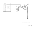
- the door system shown in FIG. 2 is a balanced door system in which a balance device 10 is designed as a counterweight which is suspended on a cable whose mass corresponds approximately to the mass of the door curtain 9.
- a balance device 10 fails, for example due to a worn rope, the door curtain 9 would shut down more or less unrestrained.
- control device 2 when comparing the set values with the actual values, detects an unwanted movement of the door which is outside a previously defined range, the control device 2 gives the frequency converter 3 a frequency preset of 0 hertz (Hz) and the speed of the electromotive drive 5 drastically to reduce or bring to a standstill.
- the electric motor drive is usually not dimensioned so that it can hold the full load of a defective Tormechanik. Therefore, it is provided in an advantageous embodiment that the control device 2 moves after detecting a fault, the gate in slow travel to a safe rest position, which may be, for example, the closed position of the gate, which is dependent on the type of gate, but also on another position.
Landscapes
- Engineering & Computer Science (AREA)
- Structural Engineering (AREA)
- Architecture (AREA)
- Civil Engineering (AREA)
- Human Computer Interaction (AREA)
- Manufacturing & Machinery (AREA)
- Physics & Mathematics (AREA)
- General Physics & Mathematics (AREA)
- Automation & Control Theory (AREA)
- Power-Operated Mechanisms For Wings (AREA)
- Control And Safety Of Cranes (AREA)
- Stopping Of Electric Motors (AREA)
Abstract
Die Erfindung betrifft ein Verfahren zum gesicherten Bremsen eines elektromotorisch angetriebenen Hubwerkes in einem Fehlerfall, wobei wenigstens ein Sollwert "Drehrichtung" und/oder "Fahrgeschwindigkeit" und/oder "Torposition" und/oder "Motorleistung" und/oder "Motorstrom" ermittelt und mit einem Istwert verglichen wird und dass bei einer außerhalb eines vorgegebenen Bereiches liegenden Abweichung des Istwertes von dem Sollwert ein motorischer Bremsvorgang oder motorischer Stoppvorgang eingeleitet wird. Darüber hinaus betrifft die Erfindung eine Vorrichtung zur Durchführung des Verfahrens.The invention relates to a method for secure braking of an electric motor-driven hoist in an error case, wherein at least one setpoint "direction of rotation" and / or "driving speed" and / or "gate position" and / or "motor power" and / or "motor current" determined and with an actual value is compared and that at a lying outside a predetermined range deviation of the actual value of the desired value, a motor braking or engine stop process is initiated. Moreover, the invention relates to a device for carrying out the method.
Description
Die Erfindung betrifft ein Verfahren zum gesicherten Bremsen eines Tores sowie eine Vorrichtung zur Durchführung des Verfahrens.The invention relates to a method for secure braking of a door and a device for carrying out the method.
Die Erfindung bezieht sich auf ein Verfahren zum gesicherten Bremsen eines Tores im Fehlerfall, das heißt im Falle eines Ausfalles einer mechanischen Komponente mit Hilfe der elektromotorischen Antriebseinheit des Tores.The invention relates to a method for secure braking of a door in case of failure, that is in the event of failure of a mechanical component by means of the electric motor drive unit of the gate.
Bei heute üblichen elektromotorisch angetriebenen Toren wie beispielsweise Rolltoren, Deckenlauftoren, Sektionaltoren oder Schwingtoren ist die Mechanik des Tores häufig so ausgelegt, dass der elektromotorische Antrieb des Tores nicht die volle Last des Tores antreiben muss. Hierzu sind die Tore abhängig von ihrer Konstruktion und Bauart mit unterschiedlichen Vorrichtungen wie beispielsweise Federelementen, Seilzügen und Kontergewichten ausgestattet, die dafür sorgen, dass nur ein Teil der zur Bewegung notwendigen Energie über den elektromotorischen Antrieb zugeführt werden muss, und die unter dem Oberbegriff der Balancevorrichtungen zusammengefasst werden können.In today usual electric motor-driven gates such as roller shutters, overhead doors, sectional doors or swing gates, the mechanics of the gate is often designed so that the electric motor drive the door does not have to drive the full load of the door. For this purpose, the gates are equipped depending on their construction and design with different devices such as spring elements, cables and counterweights, which ensure that only a portion of the energy necessary for movement must be supplied via the electric motor drive, and under the preamble of balance devices can be summarized.
Sobald eine derartige Balancevorrichtung ausfällt, weil beispielsweise eine Feder bricht oder ein mit dem Kontergewicht verbundenes Seil reißt, kann es zu einer ungewollten, unkontrollierten und gefährlichen Abwärtsbewegung, dem so genannten Absturz eines Tores kommen.As soon as such a balance device fails, for example, because a spring breaks or a rope connected to the counterweight ruptures, it can lead to an unwanted, uncontrolled and dangerous downward movement, the so-called crash of a gate.
Bei anderen zum Stand der Technik zählenden Toren sind die Konstruktion und der Antrieb so ausgelegt, dass auf eine Balancevorrichtung verzichtet wird. Bei diesen Toren stellt häufig eine zusätzliche elektromagnetische Bremsvorrichtung sicher, dass das Tor nach dem Abschalten des Antriebs in der Ruheposition gehalten wird. Bei einer Funktionsstörung der Bremsvorrichtung durch beispielsweise verschlissene Bremsbeläge kann es auch bei diesen Toren zum Absturz des Tores kommen.In other prior art gates, the design and drive are designed to eliminate the need for a balance device. In these gates, often an additional electromagnetic braking device ensures that the door is kept in the rest position after the drive has been switched off. In a malfunction of the brake device by, for example, worn brake pads, it can also come with these gates to crash the door.
Auch Kombinationen aus Balancevorrichtung und elektromechanischer Bremsvorrichtungen sind bekannt. Dabei hat die elektromechanische Bremsvorrichtung beispielsweise die Aufgabe, ein sich in Bewegung befindliches Tor schnell zum Stillstand zu bringen, falls beispielsweise ein Haltepunkt erreicht wird, und das Tor in dieser Position so lange sicher zu halten, bis ein erneuter Fahrbefehl ausgeführt werden soll.Also combinations of balance device and electromechanical braking devices are known. In this case, the electromechanical brake device, for example, the task of bringing a door in motion quickly to a halt, for example, if a breakpoint is reached, and to keep the gate in this position safe until a new move command is to be executed.
Bei einem Defekt der Bremsvorrichtung kann ein Tor unter Umständen die gewünschte Halteposition nicht erreichen oder die Halteposition wird nicht wie gewünscht gehalten, sondern das Tor beginnt langsam und ungewollt die Position zu verlassen.In the event of a malfunction of the braking device, a gate may not reach the desired holding position or the holding position is not maintained as desired, but the gate begins slowly and unintentionally to leave the position.
Zur Verhinderung eines Absturzes des Tores sind nach dem Stand der Technik diverse mechanische Lösungen bekannt wie sie beispielsweise in
Alle zum Stand der Technik gehörenden technischen Lösungen zur Verhinderung eines Torabsturzes oder zur Notbremsung haben den Nachteil, dass zusätzliche mechanische Vorrichtungen notwendig sind, deren Funktionsfähigkeit zudem in den meisten Fällen während eines normalen Lebenszyklus eines Tores nur schwer geprüft werden kann, und bei denen im Falle einer gewollten oder ungewollten Auslösung nur schwer erkennbar ist, was zum Auslösen der Vorrichtung geführt hat. Bei einigen zum Stand der Technik gehörenden Vorrichtungen ist zudem nicht erkennbar, dass sie sich im ausgelösten Zustand befinden, womit dem Benutzer der Toranlage die vermeintliche Fehlerursache erst nach aufwändiger Suche erkennbar wird.All of the prior art technical solutions for preventing a door crash or for emergency braking have the disadvantage that additional mechanical devices are necessary, whose functionality is also difficult to test in most cases during a normal life cycle of a gate, and in which case a deliberate or unwanted triggering is difficult to see, which has led to the triggering of the device. In addition, in some of the prior art devices, it is not apparent that they are in the tripped state, thus causing the user of the door system the supposed cause of the error becomes recognizable only after a time-consuming search.
Die heute üblichen elektromotorischen Antriebe für Tore, die so genannten Torantriebe, bestehen in der Regel aus einem Elektromotor, der zumeist als preiswerter asynchroner Drehstrommotor ausgeführt ist, und der in den meisten Fällen mit einem direkt angeflanschten Getriebe verbunden ist, wobei das Getriebe häufig als so genanntes Schneckengetriebe ausgeführt ist.The today usual electric motor drives for gates, the so-called door drives, usually consist of an electric motor, which is usually designed as a low-cost asynchronous three-phase motor, and which is connected in most cases with a directly flanged gear, the transmission often as so called worm gear is executed.
Gemäß dem Stand der Technik ist es ebenfalls bekannt, Torantriebe über einen Frequenzumrichter zu speisen, damit das Tor mit unterschiedlicher Geschwindigkeit verfahren werden kann, und um die Möglichkeit zum sanften Anlaufen und Stoppen des Tores zu erhalten.According to the state of the art, it is also known to feed gate drives via a frequency converter so that the gate can be moved at different speeds, and to obtain the possibility of gently starting and stopping the gate.
Der Frequenzumrichter ist hierbei gemäß dem Stand der Technik Bestandteil einer komplexen Torsteuerung, die neben dem Frequenzumrichter auch mindestens eine Vorrichtung besitzt, mit der die Position des Tores kontinuierlich ermittelt werden kann. In der
Gemäß dem Stand der Technik (
Das der Erfindung zugrunde liegende technische Problem besteht darin, ein Verfahren anzugeben, mit dem der Absturz eines Tores verhindert werden kann, ohne dass hierzu zusätzliche Vorrichtungen am Tor oder am Torantrieb notwendig sind, die sich also mit den nach dem Stand der Technik bereits vorhandenen Vorrichtungen Torantrieb, Torsteuerung, Frequenzumrichter und Positionsgeber realisieren lassen. Zusätzlich soll ein Verfahren angegeben werden, welches zumindest vorübergehend die Funktion für eine defekte elektromechanische Bremsvorrichtung des Tores übernehmen kann, und welches zuverlässig die Signalisierung einer defekten Balance- und/oder Bremsvorrichtung ermöglicht. Darüber hinaus soll eine Vorrichtung zur Durchführung des Verfahrens angegeben werden.The technical problem underlying the invention is to provide a method by which the crash of a gate can be prevented without the need for additional devices on the gate or on the door drive are necessary, so with the already existing in the prior art devices Door drive, gate control, frequency converter and position sensor can be realized. In addition, a method is to be specified, which at least temporarily can take over the function for a defective electromechanical braking device of the door, and which reliably enables the signaling of a defective balance and / or braking device. In addition, a device for carrying out the method should be specified.
Dieses technische Problem wird durch ein Verfahren mit den Merkmalen gemäß Anspruch 1 sowie durch eine Vorrichtung mit den Merkmalen gemäß Anspruch 8 gelöst.This technical problem is solved by a method having the features according to claim 1 and by a device having the features according to
Das erfindungsgemäße Verfahren zum sicheren Bremsen eines elektromotorisch angetriebenen Tores in einem Fehlerfall zeichnet sich dadurch aus, dass wenigstens ein Sollwert "Drehrichtung" und/oder "Fahrgeschwindigkeit" und/oder "Torposition" ermittelt und mit einem Istwert verglichen wird, dass die Istwerte "Drehrichtung", "Fahrgeschwindigkeit" und/oder "Torposition" von wenigstens einem Positionsgeber ermittelt werden, dass bei einer außerhalb eines vorgegebenen Bereiches liegenden Abweichung des Istwertes von dem Sollwert ein motorischer Bremsvorgang oder ein motorischer Stoppvorgang eingeleitet wird, und dass der Vergleich zwischen Soll- und Istwert permanent durchgeführt wird.The inventive method for safe braking of an electric motor driven door in case of failure is characterized in that at least one setpoint "direction of rotation" and / or "driving speed" and / or "goal position" is determined and compared with an actual value that the actual values "direction of rotation "," Driving speed "and / or" gate position "of at least one position sensor are determined that at a lying outside a predetermined range deviation of the actual value of the target value, a motor braking or a motor stop process is initiated, and that the comparison between setpoint and actual value is performed permanently.
Der besondere Vorteil der Erfindung liegt darin, dass die Istwerte "Drehrichtung", "Fahrgeschwindigkeit" und/oder "Torposition" aufgrund der Daten von wenigstens einem Positionsgeber ermittelt werden. Dies hat den Vorteil, dass der oder die ohnehin vorhandenen Positionsgeber die Istwerte an die Steuervorrichtung übermitteln und somit die Istwerte zum Vergleich mit den Sollwerten zur Verfügung stehen.The particular advantage of the invention lies in the fact that the actual values "direction of rotation", "driving speed" and / or "gate position" are determined on the basis of the data from at least one position transmitter. This has the advantage that the position sensor (s), which are present anyway, transmit the actual values to the control device and thus the actual values are available for comparison with the setpoint values.
Darüber hinaus weist die Erfindung den Vorteil auf, dass der Vergleich zwischen Soll- und Istwert permanent durchgeführt wird. Das bedeutet, dass der Vergleich während des Verfahrens des Torbehanges durchgeführt wird. Darüber hinaus soll jedoch auch bei Stillstand des Tores der wenigstens eine Istwert ermittelt und mit dem Sollwert überwacht werden. In diesem Falle kann überwacht werden, dass beispielsweise eine elektromechanische Bremsvorrichtung einen Defekt hat und das Tor sich nicht in der vorgegebenen Stillstandsposition befindet. Es kann aber auch eine defekte Balancevorrichtung erkannt werden, die das Tor im Stillstand in der jeweiligen Ruheposition halten soll.In addition, the invention has the advantage that the comparison between the setpoint and actual value is performed permanently. This means that the comparison is made during the process of the door curtain. In addition, however, should also be determined at standstill of the gate, the at least one actual value and monitored with the setpoint. In this case, it can be monitored that, for example, an electromechanical brake device has a defect and the door is not in the predetermined standstill position. However, it is also possible to detect a defective balance device which is intended to hold the door at standstill in the respective rest position.
Ein weiterer Vorteil der Erfindung liegt darin, dass im Fehlerfall ein Bremsvorgang oder ein Stoppvorgang, der überwiegend oder besonders bevorzugt ausschließlich über den Motor durchgeführt wird, eingeleitet wird.A further advantage of the invention is that, in the event of a fault, a braking operation or a stopping process, which is carried out predominantly or particularly preferably exclusively via the engine, is initiated.
Das bedeutet, dass gemäß dem erfindungsgemäßen Verfahren die genannten Sollwerte einzeln oder in Kombination erfasst werden. Diese Werte werden mit den jeweiligen Istwerten verglichen. Weichen ein oder mehrere Istwerte von den Sollwerten ab, und zwar derart, dass die Abweichungen außerhalb eines vorgegebenen Bereiches liegen, wird ein motorischer Bremsvorgang oder ein motorischer Stoppvorgang eingeleitet.This means that according to the method according to the invention, said setpoint values are detected individually or in combination. These values are compared with the respective actual values. One or more actual values deviate from the desired values, in such a way that the deviations Be outside a predetermined range, a motor braking or a motor stop process is initiated.
Beispielsweise kann über die Geschwindigkeit des Torbehanges festgestellt werden, dass beispielsweise das Seil des Kontergewichtes gerissen ist. Der Torbehang fährt in diesem Falle mit einer wesentlich größeren Geschwindigkeit als dies bei einem normalen Öffnungs- oder Schließvorgang der Fall wäre. In diesem Fall weicht der Istwert "Geschwindigkeit" von dem Sollwert ab, und es wird ein motorischer Bremsvorgang oder ein motorischer Stoppvorgang eingeleitet.For example, can be determined by the speed of the door curtain that, for example, the rope of the counterweight is cracked. The door curtain moves in this case at a much greater speed than would be the case in a normal opening or closing operation. In this case, the actual value "speed" deviates from the desired value, and a motor braking or a motor stop is initiated.
Grundsätzlich ist das Verfahren somit so ausgelegt, dass durch die ständige Überwachung der Istwerte ein jederzeitiges Abbremsen in einem Fehlerfall möglich ist.Basically, the method is thus designed so that a continuous braking in case of failure is possible by the constant monitoring of the actual values.
Die Steuervorrichtung, die den Vergleich zwischen den Ist- und den Sollwerten durchführt, ist die Steuervorrichtung, die ohnehin in der Torsteuerung vorhanden ist. Die Steuervorrichtung übernimmt also die verschiedensten Aufgaben. Die Steuervorrichtung verarbeitet die Eingangssignale. Das heißt, dass sie beispielsweise Auf- und Zubefehle der Torsteuerung verarbeitet. Die Steuervorrichtung gibt Ausgangssignale, beispielsweise gibt sie Warnsignale. Die Steuervorrichtung gibt die Frequenzvorgabe für den Frequenzumrichter. Die Steuervorrichtung verarbeitet gemäß der Erfindung die Signale von dem wenigstens einen Positionsgeber. Die Steuervorrichtung kann darüber hinaus den Motorstrom und/oder die Motorleistung bestimmen. Hierzu weist sie vorteilhaft Messvorrichtungen auf.The control device that performs the comparison between the actual and the setpoint values is the control device that is present anyway in the gate control. The control device thus takes on a wide variety of tasks. The control device processes the input signals. This means, for example, that it processes command and instruction commands. The control device gives output signals, for example, they give warning signals. The controller gives the frequency setting for the frequency converter. The control device according to the invention processes the signals from the at least one position transmitter. The controller may also determine the motor current and / or the motor power. For this purpose, it advantageously has measuring devices.
Gemäß einer weiteren vorteilhaften Ausführungsform der Erfindung wird bei dem Brems- oder Stoppvorgang einem Frequenzumrichter eine Frequenzvorgabe von 0 Hertz (Hz) vorgegeben. Mit dieser Gleichspannung wird ein asynchroner Drehstrommotor gespeist, so dass der Stoppvorgang durch eine elektromotorische Bremsung eingeleitet wird. Es ist auch möglich, die Frequenzvorgabe in einen Bereich von bis zu 20 Hertz (Hz) zu legen, um den asynchronen Drehstrommotor in langsamer Fahrt zu bewegen und die Torbewegung so weit zu verlangsamen, dass eine Gefährdung durch das sich bewegende Tor minimiert wird.According to a further advantageous embodiment of the invention, a frequency converter is in the braking or stopping process a frequency preset of 0 Hertz (Hz) is specified. With this DC voltage, an asynchronous three-phase motor is fed, so that the stop process is initiated by an electromotive braking. It is also possible to set the frequency setting in a range of up to 20 hertz (Hz) in order to move the asynchronous three-phase motor at a slow speed and to slow down the gate movement so that a risk from the moving gate is minimized.
Eine weitere vorteilhafte Ausführungsform der Erfindung sieht vor, dass bei einem Brems- oder Stoppvorgang parallel zur elektromotorischen Bremsung auch eine elektromechanische Bremsvorrichtung angesteuert wird, falls diese konstruktionsbedingt ohnehin vorhanden ist. Dies hat den Vorteil, dass der Torantrieb und der Frequenzumrichter nicht die volle Bremsleistung erbringen müssen und somit für eine geringere Leistung ausgelegt sein können. Zudem wird hierdurch die Sicherheit des Verfahrens erhöht.A further advantageous embodiment of the invention provides that in a braking or stopping operation parallel to the electromotive braking and an electromechanical braking device is driven, if this is already present due to design anyway. This has the advantage that the door drive and the frequency converter do not have to provide the full braking power and thus can be designed for lower power. In addition, this increases the security of the process.
Eine weitere vorteilhafte Ausführungsform der Erfindung sieht vor, dass nach einem Brems- oder Stoppvorgang das Tor in eine sichere Halteposition gefahren wird. Hierdurch wird die Sicherheit des gesamten Verfahrens erhöht.A further advantageous embodiment of the invention provides that after a braking or stopping operation, the gate is moved to a secure holding position. This increases the security of the entire process.
Vorteilhaft erfolgt das Verfahren des Tores durch eine Frequenzvorgabe der Steuervorrichtung an den Frequenzumrichter. Hierdurch wird erreicht, dass keine zusätzliche Vorrichtung benötigt wird, um den Bremsvorgang einzuleiten.Advantageously, the method of the gate by a frequency specification of the control device to the frequency converter. This ensures that no additional device is needed to initiate the braking process.
Gemäß einer weiteren vorteilhaften Ausführungsform der Erfindung führt die Steuervorrichtung während und/oder nach dem Einleiten des Brems- oder Stoppvorganges eine Signalisierung durch. Die Signalisierung kann zum Beispiel aus einem akustischen und/oder optischen Warnsignal bestehen.According to a further advantageous embodiment of the invention, the control device performs a signaling during and / or after the initiation of the braking or stopping process by. The signaling may for example consist of an audible and / or visual warning signal.
Die erfindungsgemäße Vorrichtung zur Durchführung des Verfahrens nach Anspruch 1 zeichnet sich dadurch aus, dass die Vorrichtung eine Steuervorrichtung aufweist, die als eine einen Vergleich von Soll- und Istwert durchführende Steuervorrichtung ausgebildet ist, und die als eine eine Frequenzvorgabe an einen Frequenzumrichter gebende Steuervorrichtung ausgebildet ist.The device according to the invention for carrying out the method according to claim 1 is characterized in that the device has a control device, which is designed as a comparison of setpoint and actual value performing control device, and which is designed as a frequency specification to a frequency converter giving control device ,
Die Steuervorrichtung vergleicht die Ist- und Sollwerte. Weichen die Istwerte von den Sollwerten ab und liegt die Abweichung außerhalb eines vorgegebenen Bereiches, so gibt die Steuervorrichtung an einen Frequenzumrichter eine Frequenzvorgabe von beispielsweise 0 Hertz (Hz), so dass ein Stoppvorgang eingeleitet wird.The control device compares the actual and setpoint values. If the actual values deviate from the desired values and the deviation is outside a predetermined range, the control device gives a frequency input to a frequency converter, for example, 0 hertz (Hz), so that a stop process is initiated.
Vorteilhaft weist die erfindungsgemäße Vorrichtung zusätzlich ein Anzeigemodul zum Anzeigen eines Fehlerfalles auf, damit ein Fehlerfall wahrgenommen werden kann.Advantageously, the device according to the invention additionally has a display module for indicating an error, so that a fault can be detected.
Gemäß einer besonders bevorzugten Ausführungsform der Erfindung ist das Anzeigemodul in der Steuervorrichtung integriert.According to a particularly preferred embodiment of the invention, the display module is integrated in the control device.
Vorteilhaft ist zusätzlich wenigstens eine elektromechanische Bremsvorrichtung vorgesehen. Diese hält das Tor vorteilhaft in einer Endlage und soll vorteilhaft gemäß dem Ruhestromprinzip unterstützend zum Motor die Bremswirkung ausüben.Advantageously, at least one electromechanical brake device is additionally provided. This holds the goal advantageous in an end position and should advantageously exercise in accordance with the closed-circuit principle supporting the engine, the braking effect.
Dabei erfüllt die vorliegende Erfindung auch die geltenden Vorschriften und technischen Regeln, nach denen von einer Toranlage bei Auftreten eines Einfachfehlers keine Gefahr ausgehen darf.In this case, the present invention also meets the applicable regulations and technical rules, according to which of a door system must not pose a risk if a single fault occurs.
Erreicht wird dieses Ziel durch eine Verknüpfung der nach dem Stand der Technik zu einer Torsteuerung gehörenden Komponenten Torantrieb, Torsteuerung mit Frequenzumrichter und Positionsgeber zur kontinuierlichen Positionserfassung, wobei der Frequenzumrichter nicht zwingend ein in die Torsteuerung integrierter Bestandteil sein muss, sondern auch als mehr oder weniger separate Einheit ausgeführt sein kann, die jedoch von der Torsteuerung angesteuert werden kann.This goal is achieved by a combination of belonging to the prior art to a door control components door drive, door control with frequency converter and position sensor for continuous position detection, the frequency converter does not necessarily have to be integrated into the gate control component, but also as more or less separate Unit may be executed, but which can be controlled by the gate control.
Die vorliegende Erfindung macht sich dabei die Tatsache zu Nutze, dass bei entsprechender Auslegung über einen Frequenzumrichter auch eine Wechselspannung mit einer Frequenz von 0 Hertz (Hz), also eine Gleichspannung ausgegeben werden kann. Die Speisung eines asynchronen Drehstrommotors mit einer Gleichspannung hat zur Folge, dass dieser mit einer sehr geringen Geschwindigkeit im Quasi-Stillstand verharrt, was dazu führt, dass das angekoppelte Tor nahezu in seiner augenblicklichen Stellung gehalten werden kann.The present invention takes advantage of the fact that with appropriate design via a frequency converter and an AC voltage with a frequency of 0 hertz (Hz), ie a DC voltage can be output. The supply of an asynchronous three-phase motor with a DC voltage has the result that it remains at a very low speed in quasi-stagnation, with the result that the docked gate can be held almost in its current position.
Bei dem erfindungsgemäßen Verfahren, welches als Software oder Firmware in die logischen Abläufe der Steuervorrichtung der Torsteuerung integriert wird, erfolgt eine kontinuierliche Kontrolle bezüglich der augenblicklichen Position des Tores und/oder ob ein Fahrbefehl zum Bewegen des Tores ausgeführt werden soll und mit welcher Geschwindigkeit und in welche Richtung sich das Tor bewegen soll.In the method according to the invention, which is integrated as software or firmware in the logical operations of the control device of the door control, there is a continuous control with respect to the instantaneous position of the door and / or if a movement command to move the gate to be executed and at what speed and in which direction the goal should move.
Stellt die erfindungsgemäße Steuervorrichtung eine zuvor definierte Abweichung zwischen der Sollgeschwindigkeit oder Sollbewegungsrichtung des Tores und der tatsächlichen über den Positionsgeber ermittelten Bewegungsrichtung und Geschwindigkeit des Tores fest, wobei die Begriffe Soll-Bewegungsrichtung und Soll-Geschwindigkeit auch den Stillstand einbeziehen, löst die Steuervorrichtung die Zwangsbremsung des Tores aus, indem sie dem Frequenzumrichter eine Frequenzvorgabe von 0 Hertz bis 20 Hertz (Hz) übermittelt, um die Torbewegung zu stoppen oder zumindest drastisch zu reduzieren.Does the control device according to the invention a previously defined deviation between the desired speed or target movement direction of the gate and the actual Determining the direction of movement and speed of the door determined by the position transmitter, the terms target direction of movement and set speed also including the standstill, the control device triggers the emergency braking of the gate by giving the frequency converter a frequency specification of 0 Hertz to 20 Hertz (Hz). transmitted to stop or at least drastically reduce the gate movement.
Ob die Torbewegung dabei dauerhaft oder lediglich vorübergehend gestoppt oder drastisch reduziert werden kann, ist hierbei unabhängig vom erfindungsgemäßen Verfahren, sondern abhängig von der elektrischen und mechanischen Leistungsfähigkeit des Torantriebes und des Frequenzumrichters und der gegebenenfalls vorhandenen elektromechanischen Bremsvorrichtung.Whether the door movement thereby permanently or only temporarily stopped or drastically reduced, this is independent of the method according to the invention, but depending on the electrical and mechanical performance of the door drive and the frequency converter and the optionally existing electromechanical braking device.
In einer weiteren vorteilhaften Ausführungsform kann die erfindungsgemäße Steuervorrichtung nach dem Feststellen einer oben beschriebenen Bedingung auch eine Frequenzvorgabe an den Frequenzumrichter übermitteln, mit dem das Tor in langsamer Fahrt eine sichere Halteposition wie beispielsweise die Zu-Position anfahren kann. Bei diesem Vorgehen ist dann gewährleistet, dass keine weitere Gefahr von der vermeintlich defekten Toranlage, die aus Tor, Torantrieb und Torsteuerung besteht, mehr ausgehen kann.In a further advantageous embodiment, the control device according to the invention can also transmit, after determining a condition described above, a frequency specification to the frequency converter with which the door can travel to a safe stop position, such as the closed position, when driving slowly. This procedure ensures that no further danger can arise from the supposedly defective door system consisting of gate, door drive and door control.
In einer weiteren vorteilhaften Ausführungsform veranlasst die erfindungsgemäße Steuervorrichtung die Signalisierung des erkannten Fehlerfalles, so dass außenstehende Personen auf den Fehlerfall aufmerksam gemacht werden und eine rasche Fehlersuche und Fehlerbeseitigung veranlasst werden kann.In a further advantageous embodiment, the control device according to the invention causes the signaling of the detected error case, so that outside persons are made aware of the error case and can be promptly troubleshooting and error correction.
Weitere Merkmale und Vorteile der Erfindung ergeben sich anhand der zugehörigen Zeichnung, in der mehrere Ausführungsbeispiele einer erfindungsgemäßen Torsteuerung zum gesicherten Abbremsen eines Tores nur beispielhaft dargestellt sind. In der Zeichnung zeigen:
- Fig. 1
- schematisch eine Toranlage mit einem Rolltor und einer elektromechanischen Bremse;
- Fig. 2
- schematisch eine Toranlage mit einer Balance-vorrichtung.
- Fig. 1
- schematically a door system with a roller door and an electromechanical brake;
- Fig. 2
- schematically a door system with a balance device.
In Fig. 1 ist eine Torsteuerung 1 dargestellt, die einen Frequenzumrichter 3 und eine Steuervorrichtung 2 enthält. Im Normalbetrieb erhält der Frequenzumrichter 3 von der Steuervorrichtung 2 eine Vorgabe für die abzugebende Frequenz und Drehrichtung, mit der ein elektromotorischer Antrieb 5 zu speisen ist, der über eine Antriebswelle 8 mit einer Torwelle 7 mechanisch verbunden ist und auf diesem Weg einen Torbehang 9 in Bewegung versetzen kann.In Fig. 1, a gate control 1 is shown, which includes a
Über einen Positionsgeber 4, der zwischen dem elektromotorischen Antrieb 5 und der Torwelle 7 oder auf oder an der Torwelle 7 angeordnet sein kann oder in den elektromotorischen Antrieb 5 integriert sein kann oder an einer anderen Stelle angeordnet sein kann, und der als Absolutwertgeber oder Inkrementalgeber ausgeführt sein kann, kann sich die Steuervorrichtung 2 ständig über die tatsächliche Position und Geschwindigkeit des Torantriebes 5 und des damit mechanisch gekoppelten Torbehangs 9 informieren.About a
Die erfindungsgemäße Steuervorrichtung 2 ist Bestandteil der Torsteuerung 1 und nur schematisch dargestellt, da sie als Softwaremodul in die logischen Abläufe eingebunden wird. Die Steuervorrichtung 2 ist ohnehin in der Torsteuerung 1 enthalten und übernimmt gemäß der Erfindung lediglich zusätzliche Aufgaben.The
Die erfindungsgemäße Steuervorrichtung 2 verarbeitet die intern vorliegenden aktuellen Sollwerte "Drehrichtung" und "Fahrgeschwindigkeit" und vergleicht diese mit den Istwerten der vom Positionsgeber 4 gelieferten Angaben, aus denen neben der augenblicklichen Torposition auch die Drehrichtung und die Momentangeschwindigkeit des Torantriebes ermittelt werden kann.The
Stellt die Steuervorrichtung 2 beim Vergleich der Sollwerte mit den Istwerten eine Abweichung fest, die außerhalb eines zuvor definierten Bereiches liegt, steuert die Steuervorrichtung 2 den Frequenzumrichter 3 an und gibt dem Frequenzumrichter 3 eine Frequenzvorgabe von 0 Hertz (Hz), um die Geschwindigkeit des elektromotorischen Antriebes 5 drastisch zu reduzieren oder zum Stillstand zu bringen. Gleichzeitig steuert die erfindungsgemäße Steuervorrichtung 2 eine Bremsvorrichtung 6 an, damit diese den Bremsvorgang unterstützt. Diese Bremsvorrichtung 6 ist als elektromechanische Bremsvorrichtung ausgebildet.If the
Bei der in Fig. 1 dargestellten Ausführungsform der Toranlage kann das erfindungsgemäße Verfahren auch dazu eingesetzt werden, die Funktion des Antriebes 5 zu überwachen. Für den Fall, dass der Antrieb 5 beispielsweise aufgrund von mechanischem Verschleiß den Torbehang 9 nicht in der geforderten Art bewegen oder halten kann, kann über die erfindungsgemäße Steuervorrichtung 2 jederzeit die Bremsvorrichtung 6 angesteuert werden, um den Torbehang 9 abzubremsen.In the embodiment of the door system shown in Fig. 1, the inventive method can also be used to monitor the function of the drive 5. In the event that the drive 5, for example due to mechanical wear, can not move or hold the
Bei der in Fig. 2 dargestellten Toranlage handelt es sich um eine ausbalancierte Toranlage, bei der eine Balancevorrichtung 10 als Kontergewicht, welches an einem Seil aufgehängt ist, ausgeführt ist, dessen Masse in etwa der Masse des Torbehanges 9 entspricht. Für den Fall, dass die Balancevorrichtung 10 beispielsweise aufgrund eines verschlissenen Seiles ausfällt, würde der Torbehang 9 mehr oder weniger ungebremst herunterfahren.The door system shown in FIG. 2 is a balanced door system in which a
Stellt die Steuervorrichtung 2 beim Vergleich der Sollwerte mit den Istwerten eine ungewollte Bewegung des Tores fest, die außerhalb eines zuvor definierten Bereiches liegt, gibt die Steuervorrichtung 2 dem Frequenzumrichter 3 eine Frequenzvorgabe von 0 Hertz (Hz), um die Geschwindigkeit des elektromotorischen Antriebes 5 drastisch zu reduzieren oder zum Stillstand zu bringen.If the
Der elektromotorische Antrieb ist in der Regel nicht so dimensioniert, dass er die volle Last einer defekten Tormechanik halten kann. Deshalb ist es in einer vorteilhaften Ausführungsform vorgesehen, dass die Steuervorrichtung 2 nach Feststellen eines Fehlerfalles das Tor in langsamer Fahrt in eine sichere Ruheposition bewegt, die beispielsweise die Zu-Position des Tores sein kann, die abhängig vom Typ des Tores ist, aber auch an einer anderen Position sein kann.The electric motor drive is usually not dimensioned so that it can hold the full load of a defective Tormechanik. Therefore, it is provided in an advantageous embodiment that the
- 11
- TorsteuerungGate control
- 22
- Steuervorrichtungcontrol device
- 33
- Frequenzumrichterfrequency converter
- 44
- Positionsgeberlocator
- 55
- elektromotorischer Antriebelectric motor drive
- 66
- Bremsvorrichtungbraking device
- 77
- Torwelledoor shaft
- 88th
- Antriebswelledrive shaft
- 99
- TorbehangDoor curtain
- 1010
- Balancevorrichtungbalance device
Claims (11)
Applications Claiming Priority (1)
| Application Number | Priority Date | Filing Date | Title |
|---|---|---|---|
| DE102006034962A DE102006034962B4 (en) | 2006-07-28 | 2006-07-28 | Method for secure braking of a gate and device for carrying out the method |
Publications (3)
| Publication Number | Publication Date |
|---|---|
| EP1882802A2 true EP1882802A2 (en) | 2008-01-30 |
| EP1882802A3 EP1882802A3 (en) | 2009-07-22 |
| EP1882802B1 EP1882802B1 (en) | 2016-08-10 |
Family
ID=38610850
Family Applications (1)
| Application Number | Title | Priority Date | Filing Date |
|---|---|---|---|
| EP07111601.6A Active EP1882802B1 (en) | 2006-07-28 | 2007-07-03 | Method for safe braking of a gate and device for implementing the method |
Country Status (4)
| Country | Link |
|---|---|
| US (1) | US7723936B2 (en) |
| EP (1) | EP1882802B1 (en) |
| DE (1) | DE102006034962B4 (en) |
| DK (1) | DK1882802T3 (en) |
Cited By (5)
| Publication number | Priority date | Publication date | Assignee | Title |
|---|---|---|---|---|
| DE102016207029A1 (en) * | 2016-04-26 | 2017-10-26 | Geze Gmbh | Drive unit and method for closing a wing of a door or a window |
| WO2018109191A1 (en) * | 2016-12-15 | 2018-06-21 | Gabrijel Rejc Gmbh & Co. Kg | Door having a fall protection mechanism and method for triggering the fall protection mechanism |
| CN110139962A (en) * | 2016-12-22 | 2019-08-16 | 百立富设计与工程私营有限公司 | Pull-down flood defence barrier |
| US10829989B2 (en) | 2016-06-28 | 2020-11-10 | Gabrijel Rejc | Motor-operable and vertically movable gate |
| US10914117B2 (en) | 2016-06-28 | 2021-02-09 | Gabrijel Rejc | Vertically movable gate with a gate panel |
Families Citing this family (11)
| Publication number | Priority date | Publication date | Assignee | Title |
|---|---|---|---|---|
| DE102009008132B4 (en) * | 2009-02-09 | 2011-09-15 | Feig Electronic Gmbh | Gate control for controlling a motor driven gate |
| DE102011107866A1 (en) * | 2011-07-18 | 2013-01-24 | Novoferm Tormatic Gmbh | Method for operating a building closure |
| SI2887535T1 (en) * | 2013-12-23 | 2018-05-31 | Gabrijel Rejc Gmbh & Co. Kg | Drive and control system for raising gates |
| JP6235920B2 (en) * | 2014-01-31 | 2017-11-22 | 三和シヤッター工業株式会社 | Abnormality judgment device of position detection sensor in electric shutter for building |
| US9663981B2 (en) * | 2014-04-02 | 2017-05-30 | Ford Global Technologies, Llc | Vehicle closure member power actuator control |
| US10144614B2 (en) | 2014-12-17 | 2018-12-04 | Hangzhou Huning Elevator Parts Co., Ltd. | Power-loss triggering device |
| US11142939B2 (en) | 2019-12-13 | 2021-10-12 | Schlage Lock Company Llc | Power boost module |
| WO2021255139A1 (en) | 2020-06-17 | 2021-12-23 | Assa Abloy Entrance Systems Ab | Overhead door operator system |
| DE102021114570B4 (en) | 2021-04-22 | 2025-07-10 | Hörmann KG Antriebstechnik | Operating procedure, control and building or fence closure drive device with frequency converter |
| DE102022119074A1 (en) | 2022-07-29 | 2024-02-01 | Feig Electronic Gmbh | Drive device for moving a darkening, adjusting or closing device |
| CN121576006A (en) * | 2026-01-23 | 2026-02-27 | 山西建筑工程集团有限公司 | A method and system for starting and stopping roller shutter doors |
Citations (1)
| Publication number | Priority date | Publication date | Assignee | Title |
|---|---|---|---|---|
| US6445152B1 (en) | 1999-11-24 | 2002-09-03 | Westinghouse Air Brake Co. | Door control system |
Family Cites Families (17)
| Publication number | Priority date | Publication date | Assignee | Title |
|---|---|---|---|---|
| DE1701251U (en) | 1954-03-12 | 1955-06-23 | Siemens Ag | CERAMIC ISOLATOR (BONE INSULATOR) FOR SUSPENSION, PREFERABLY FROM BONE WIRES. |
| US4698622A (en) * | 1984-04-16 | 1987-10-06 | Daihatsu Diesel Mfg. Co., Ltd. | Brake apparatus for automatic door |
| DE3701251A1 (en) * | 1987-01-17 | 1988-07-28 | Menke Wilhelm | COLLAR DEVICE FOR ROLLING DOORS WITH CLAMP RING |
| AT387258B (en) * | 1987-04-28 | 1988-12-27 | Novoferm Stahlbauwerk Kg | CASE BRAKE |
| JPH079127B2 (en) * | 1989-08-17 | 1995-02-01 | ワイケイケイ株式会社 | Automatic door opening / closing control method |
| DE59006423D1 (en) * | 1989-11-27 | 1994-08-18 | Inventio Ag | Method and device for reducing the risk of getting caught in automatic doors. |
| DE4138711C2 (en) * | 1991-11-20 | 1996-07-04 | Dancho Zochev Dipl Ing Donkov | Fall protection for a lifting gate |
| DE4207705C1 (en) * | 1992-03-11 | 1993-04-29 | Dorma Gmbh + Co. Kg, 5828 Ennepetal, De | |
| US5512883A (en) * | 1992-11-03 | 1996-04-30 | Lane, Jr.; William E. | Method and device for monitoring the operation of a motor |
| DE29513962U1 (en) * | 1995-08-31 | 1995-10-19 | Feig electronic GmbH, 35781 Weilburg | Control device for power operated doors, gates and barriers |
| US6078263A (en) * | 1996-02-20 | 2000-06-20 | Rs Parts Distributors, Inc. | Method and apparatus for ensuring safe operation of electric overhead door |
| JP3299135B2 (en) * | 1996-02-28 | 2002-07-08 | 株式会社ナブコ | Control device for automatic door device |
| DE19645811C2 (en) * | 1996-11-07 | 1998-10-01 | Stahl R Foerdertech Gmbh | Control arrangement for emergency shutdown |
| DE19855697C2 (en) * | 1998-07-27 | 2003-02-27 | Hoermann Kg | A spring monitoring device |
| US6388412B1 (en) * | 2000-05-09 | 2002-05-14 | Overhead Door Corporation | Door operator control system and method |
| DE10142431B4 (en) * | 2001-08-31 | 2005-07-07 | Feig Electronic Gmbh | Control device for high-speed doors |
| FR2868112A1 (en) * | 2004-03-24 | 2005-09-30 | Meridionale Des Clotures Et Me | Casement opening, closing and locking device for portal located at entry of residence, has reducer to transmit mechanical torque between output shaft of motor and casement, and brake to lock casement in closed/open position |
-
2006
- 2006-07-28 DE DE102006034962A patent/DE102006034962B4/en not_active Withdrawn - After Issue
-
2007
- 2007-07-03 EP EP07111601.6A patent/EP1882802B1/en active Active
- 2007-07-03 DK DK07111601.6T patent/DK1882802T3/en active
- 2007-07-27 US US11/829,355 patent/US7723936B2/en active Active
Patent Citations (1)
| Publication number | Priority date | Publication date | Assignee | Title |
|---|---|---|---|---|
| US6445152B1 (en) | 1999-11-24 | 2002-09-03 | Westinghouse Air Brake Co. | Door control system |
Cited By (9)
| Publication number | Priority date | Publication date | Assignee | Title |
|---|---|---|---|---|
| DE102016207029A1 (en) * | 2016-04-26 | 2017-10-26 | Geze Gmbh | Drive unit and method for closing a wing of a door or a window |
| US10829989B2 (en) | 2016-06-28 | 2020-11-10 | Gabrijel Rejc | Motor-operable and vertically movable gate |
| US10914117B2 (en) | 2016-06-28 | 2021-02-09 | Gabrijel Rejc | Vertically movable gate with a gate panel |
| WO2018109191A1 (en) * | 2016-12-15 | 2018-06-21 | Gabrijel Rejc Gmbh & Co. Kg | Door having a fall protection mechanism and method for triggering the fall protection mechanism |
| JP2020514577A (en) * | 2016-12-15 | 2020-05-21 | ガブリイエル レイツ ゲゼルシャフト ミット ベシュレンクテル ハフツング ウント コンパニー コマンディトゲゼルシャフト | Gate having a fall prevention mechanism and method of triggering the fall prevention mechanism |
| EA036915B1 (en) * | 2016-12-15 | 2021-01-14 | Габриель Рейк ГмбХ унд Ко. КГ | Gate with a fall prevention mechanism and method for triggering the fall prevention mechanism |
| JP7021220B2 (en) | 2016-12-15 | 2022-02-16 | ガブリイエル レイツ ゲゼルシャフト ミット ベシュレンクテル ハフツング ウント コンパニー コマンディトゲゼルシャフト | A gate with a collapse prevention mechanism and a method of triggering a collapse prevention mechanism |
| US11499369B2 (en) | 2016-12-15 | 2022-11-15 | Gabrijel Rejc Gmbh & Co. Kg | Gate with a crash-down prevention mechanism and method for triggering the crash-down prevention mechanism |
| CN110139962A (en) * | 2016-12-22 | 2019-08-16 | 百立富设计与工程私营有限公司 | Pull-down flood defence barrier |
Also Published As
| Publication number | Publication date |
|---|---|
| DK1882802T3 (en) | 2016-09-26 |
| DE102006034962B4 (en) | 2010-07-08 |
| DE102006034962A1 (en) | 2008-01-31 |
| EP1882802B1 (en) | 2016-08-10 |
| US20080036409A1 (en) | 2008-02-14 |
| EP1882802A3 (en) | 2009-07-22 |
| US7723936B2 (en) | 2010-05-25 |
Similar Documents
| Publication | Publication Date | Title |
|---|---|---|
| EP1882802B1 (en) | Method for safe braking of a gate and device for implementing the method | |
| EP0730791B1 (en) | Process for regulating an automatic door operated by a drive motor | |
| DE112009004592B4 (en) | Elevator installation and method for checking the same | |
| EP2887535B1 (en) | Drive and control system for raising gates | |
| DE4214998C2 (en) | Door drive and method for operating a door drive | |
| DE102010002870B4 (en) | Sliding door system and method for operating a sliding door system | |
| EP2457860B1 (en) | Safety device for a lift | |
| DE112013000152T5 (en) | Braking power verification device for a press machine | |
| EP3209589A1 (en) | Elevator comprising a decentralized electronic safety system | |
| EP2160349B1 (en) | Arrangement, module and method for reliably operating a system | |
| EP3704048B1 (en) | Safety monitoring device for monitoring of safety conditions in a device for transporting people and method for operating the same | |
| WO2010066318A1 (en) | Method and device for controlling a manipulator system | |
| EP3196392B1 (en) | Electric motor drive with closure spring | |
| EP1806837B1 (en) | Method for testing the braking function of a robot drive | |
| DE202016101183U1 (en) | Elevator with a safety controller for directly influencing the braking force | |
| DE102010051413A1 (en) | Drive system for e.g. stacker crane, has comparison unit that compares balance between braking distance and spacing between end position and respective axle position for sending trip signal for triggering brake | |
| EP2540952A2 (en) | Monitoring device for weight balancing device and building closure comprising same and door drive | |
| DE102004017110A1 (en) | Vehicle window lever, for an electrically raised and lowered window panel, has a control unit that is configured so that the drive motor is supplied with sufficient power to maintain the window panel in a selected position | |
| EP2047171B2 (en) | Method for protecting personnel during operation of a servo press and servo press comprising a personnel protection device | |
| EP3649315B1 (en) | Automatic door system | |
| EP3564419B1 (en) | Bale opener with a height-adjustable pickup unit and a brake unit for same | |
| EP2463223A1 (en) | Method and device for monitoring the stopping position of a lift cabin | |
| WO2017121760A1 (en) | Method for monitoring a first brake of a car of an elevator system | |
| DE102005059790A1 (en) | Control mechanism for elevators using a ball screw | |
| AT508404B1 (en) | METHOD FOR CONTROLLING AN ELEVATOR |
Legal Events
| Date | Code | Title | Description |
|---|---|---|---|
| PUAI | Public reference made under article 153(3) epc to a published international application that has entered the european phase |
Free format text: ORIGINAL CODE: 0009012 |
|
| AK | Designated contracting states |
Kind code of ref document: A2 Designated state(s): AT BE BG CH CY CZ DE DK EE ES FI FR GB GR HU IE IS IT LI LT LU LV MC MT NL PL PT RO SE SI SK TR |
|
| AX | Request for extension of the european patent |
Extension state: AL BA HR MK YU |
|
| PUAL | Search report despatched |
Free format text: ORIGINAL CODE: 0009013 |
|
| AK | Designated contracting states |
Kind code of ref document: A3 Designated state(s): AT BE BG CH CY CZ DE DK EE ES FI FR GB GR HU IE IS IT LI LT LU LV MC MT NL PL PT RO SE SI SK TR |
|
| AX | Request for extension of the european patent |
Extension state: AL BA HR MK RS |
|
| 17P | Request for examination filed |
Effective date: 20100112 |
|
| AKX | Designation fees paid |
Designated state(s): AT BE BG CH CY CZ DE DK EE ES FI FR GB GR HU IE IS IT LI LT LU LV MC MT NL PL PT RO SE SI SK TR |
|
| AXX | Extension fees paid |
Extension state: AL Payment date: 20100122 Extension state: RS Payment date: 20100122 Extension state: MK Payment date: 20100122 Extension state: HR Payment date: 20100122 Extension state: BA Payment date: 20100122 |
|
| 17Q | First examination report despatched |
Effective date: 20140217 |
|
| REG | Reference to a national code |
Ref country code: DE Ref legal event code: R079 Ref document number: 502007014997 Country of ref document: DE Free format text: PREVIOUS MAIN CLASS: E05F0015200000 Ipc: E05F0015000000 |
|
| GRAP | Despatch of communication of intention to grant a patent |
Free format text: ORIGINAL CODE: EPIDOSNIGR1 |
|
| RIC1 | Information provided on ipc code assigned before grant |
Ipc: E05F 15/00 20150101AFI20160229BHEP Ipc: E05F 15/40 20150101ALI20160229BHEP Ipc: E05D 13/00 20060101ALI20160229BHEP Ipc: E06B 9/84 20060101ALI20160229BHEP Ipc: G05B 19/416 20060101ALI20160229BHEP |
|
| INTG | Intention to grant announced |
Effective date: 20160315 |
|
| GRAS | Grant fee paid |
Free format text: ORIGINAL CODE: EPIDOSNIGR3 |
|
| GRAA | (expected) grant |
Free format text: ORIGINAL CODE: 0009210 |
|
| AK | Designated contracting states |
Kind code of ref document: B1 Designated state(s): AT BE BG CH CY CZ DE DK EE ES FI FR GB GR HU IE IS IT LI LT LU LV MC MT NL PL PT RO SE SI SK TR |
|
| AX | Request for extension of the european patent |
Extension state: AL BA HR MK RS |
|
| REG | Reference to a national code |
Ref country code: GB Ref legal event code: FG4D Free format text: NOT ENGLISH |
|
| REG | Reference to a national code |
Ref country code: CH Ref legal event code: EP Ref country code: CH Ref legal event code: NV Representative=s name: BOVARD AG, CH Ref country code: AT Ref legal event code: REF Ref document number: 819228 Country of ref document: AT Kind code of ref document: T Effective date: 20160815 |
|
| REG | Reference to a national code |
Ref country code: IE Ref legal event code: FG4D Free format text: LANGUAGE OF EP DOCUMENT: GERMAN |
|
| REG | Reference to a national code |
Ref country code: DE Ref legal event code: R096 Ref document number: 502007014997 Country of ref document: DE |
|
| REG | Reference to a national code |
Ref country code: DK Ref legal event code: T3 Effective date: 20160922 |
|
| REG | Reference to a national code |
Ref country code: SE Ref legal event code: TRGR |
|
| REG | Reference to a national code |
Ref country code: NL Ref legal event code: FP |
|
| REG | Reference to a national code |
Ref country code: LT Ref legal event code: MG4D |
|
| PG25 | Lapsed in a contracting state [announced via postgrant information from national office to epo] |
Ref country code: IS Free format text: LAPSE BECAUSE OF FAILURE TO SUBMIT A TRANSLATION OF THE DESCRIPTION OR TO PAY THE FEE WITHIN THE PRESCRIBED TIME-LIMIT Effective date: 20161210 Ref country code: LT Free format text: LAPSE BECAUSE OF FAILURE TO SUBMIT A TRANSLATION OF THE DESCRIPTION OR TO PAY THE FEE WITHIN THE PRESCRIBED TIME-LIMIT Effective date: 20160810 Ref country code: FI Free format text: LAPSE BECAUSE OF FAILURE TO SUBMIT A TRANSLATION OF THE DESCRIPTION OR TO PAY THE FEE WITHIN THE PRESCRIBED TIME-LIMIT Effective date: 20160810 |
|
| PG25 | Lapsed in a contracting state [announced via postgrant information from national office to epo] |
Ref country code: ES Free format text: LAPSE BECAUSE OF FAILURE TO SUBMIT A TRANSLATION OF THE DESCRIPTION OR TO PAY THE FEE WITHIN THE PRESCRIBED TIME-LIMIT Effective date: 20160810 Ref country code: PT Free format text: LAPSE BECAUSE OF FAILURE TO SUBMIT A TRANSLATION OF THE DESCRIPTION OR TO PAY THE FEE WITHIN THE PRESCRIBED TIME-LIMIT Effective date: 20161212 Ref country code: PL Free format text: LAPSE BECAUSE OF FAILURE TO SUBMIT A TRANSLATION OF THE DESCRIPTION OR TO PAY THE FEE WITHIN THE PRESCRIBED TIME-LIMIT Effective date: 20160810 Ref country code: GR Free format text: LAPSE BECAUSE OF FAILURE TO SUBMIT A TRANSLATION OF THE DESCRIPTION OR TO PAY THE FEE WITHIN THE PRESCRIBED TIME-LIMIT Effective date: 20161111 Ref country code: LV Free format text: LAPSE BECAUSE OF FAILURE TO SUBMIT A TRANSLATION OF THE DESCRIPTION OR TO PAY THE FEE WITHIN THE PRESCRIBED TIME-LIMIT Effective date: 20160810 |
|
| PG25 | Lapsed in a contracting state [announced via postgrant information from national office to epo] |
Ref country code: EE Free format text: LAPSE BECAUSE OF FAILURE TO SUBMIT A TRANSLATION OF THE DESCRIPTION OR TO PAY THE FEE WITHIN THE PRESCRIBED TIME-LIMIT Effective date: 20160810 Ref country code: RO Free format text: LAPSE BECAUSE OF FAILURE TO SUBMIT A TRANSLATION OF THE DESCRIPTION OR TO PAY THE FEE WITHIN THE PRESCRIBED TIME-LIMIT Effective date: 20160810 |
|
| REG | Reference to a national code |
Ref country code: DE Ref legal event code: R097 Ref document number: 502007014997 Country of ref document: DE |
|
| PG25 | Lapsed in a contracting state [announced via postgrant information from national office to epo] |
Ref country code: CZ Free format text: LAPSE BECAUSE OF FAILURE TO SUBMIT A TRANSLATION OF THE DESCRIPTION OR TO PAY THE FEE WITHIN THE PRESCRIBED TIME-LIMIT Effective date: 20160810 Ref country code: SK Free format text: LAPSE BECAUSE OF FAILURE TO SUBMIT A TRANSLATION OF THE DESCRIPTION OR TO PAY THE FEE WITHIN THE PRESCRIBED TIME-LIMIT Effective date: 20160810 Ref country code: BG Free format text: LAPSE BECAUSE OF FAILURE TO SUBMIT A TRANSLATION OF THE DESCRIPTION OR TO PAY THE FEE WITHIN THE PRESCRIBED TIME-LIMIT Effective date: 20161110 |
|
| PLBE | No opposition filed within time limit |
Free format text: ORIGINAL CODE: 0009261 |
|
| STAA | Information on the status of an ep patent application or granted ep patent |
Free format text: STATUS: NO OPPOSITION FILED WITHIN TIME LIMIT |
|
| 26N | No opposition filed |
Effective date: 20170511 |
|
| REG | Reference to a national code |
Ref country code: FR Ref legal event code: PLFP Year of fee payment: 11 |
|
| PG25 | Lapsed in a contracting state [announced via postgrant information from national office to epo] |
Ref country code: SI Free format text: LAPSE BECAUSE OF FAILURE TO SUBMIT A TRANSLATION OF THE DESCRIPTION OR TO PAY THE FEE WITHIN THE PRESCRIBED TIME-LIMIT Effective date: 20160810 |
|
| PGFP | Annual fee paid to national office [announced via postgrant information from national office to epo] |
Ref country code: NL Payment date: 20170719 Year of fee payment: 11 Ref country code: TR Payment date: 20170628 Year of fee payment: 11 |
|
| PGFP | Annual fee paid to national office [announced via postgrant information from national office to epo] |
Ref country code: CZ Payment date: 20170522 Year of fee payment: 6 Ref country code: GB Payment date: 20170719 Year of fee payment: 11 |
|
| PGFP | Annual fee paid to national office [announced via postgrant information from national office to epo] |
Ref country code: AT Payment date: 20170720 Year of fee payment: 11 |
|
| REG | Reference to a national code |
Ref country code: IE Ref legal event code: MM4A |
|
| PG25 | Lapsed in a contracting state [announced via postgrant information from national office to epo] |
Ref country code: IE Free format text: LAPSE BECAUSE OF NON-PAYMENT OF DUE FEES Effective date: 20170703 |
|
| PG25 | Lapsed in a contracting state [announced via postgrant information from national office to epo] |
Ref country code: LU Free format text: LAPSE BECAUSE OF NON-PAYMENT OF DUE FEES Effective date: 20170703 |
|
| PG25 | Lapsed in a contracting state [announced via postgrant information from national office to epo] |
Ref country code: MT Free format text: LAPSE BECAUSE OF FAILURE TO SUBMIT A TRANSLATION OF THE DESCRIPTION OR TO PAY THE FEE WITHIN THE PRESCRIBED TIME-LIMIT Effective date: 20160810 |
|
| REG | Reference to a national code |
Ref country code: CH Ref legal event code: PL |
|
| REG | Reference to a national code |
Ref country code: NL Ref legal event code: MM Effective date: 20180801 |
|
| REG | Reference to a national code |
Ref country code: AT Ref legal event code: MM01 Ref document number: 819228 Country of ref document: AT Kind code of ref document: T Effective date: 20180703 |
|
| GBPC | Gb: european patent ceased through non-payment of renewal fee |
Effective date: 20180703 |
|
| PG25 | Lapsed in a contracting state [announced via postgrant information from national office to epo] |
Ref country code: LI Free format text: LAPSE BECAUSE OF NON-PAYMENT OF DUE FEES Effective date: 20180731 Ref country code: AT Free format text: LAPSE BECAUSE OF NON-PAYMENT OF DUE FEES Effective date: 20180703 Ref country code: CH Free format text: LAPSE BECAUSE OF NON-PAYMENT OF DUE FEES Effective date: 20180731 Ref country code: FR Free format text: LAPSE BECAUSE OF NON-PAYMENT OF DUE FEES Effective date: 20180731 Ref country code: GB Free format text: LAPSE BECAUSE OF NON-PAYMENT OF DUE FEES Effective date: 20180703 |
|
| PG25 | Lapsed in a contracting state [announced via postgrant information from national office to epo] |
Ref country code: NL Free format text: LAPSE BECAUSE OF NON-PAYMENT OF DUE FEES Effective date: 20180801 |
|
| PG25 | Lapsed in a contracting state [announced via postgrant information from national office to epo] |
Ref country code: HU Free format text: LAPSE BECAUSE OF FAILURE TO SUBMIT A TRANSLATION OF THE DESCRIPTION OR TO PAY THE FEE WITHIN THE PRESCRIBED TIME-LIMIT; INVALID AB INITIO Effective date: 20070703 Ref country code: MC Free format text: LAPSE BECAUSE OF FAILURE TO SUBMIT A TRANSLATION OF THE DESCRIPTION OR TO PAY THE FEE WITHIN THE PRESCRIBED TIME-LIMIT Effective date: 20160810 |
|
| PG25 | Lapsed in a contracting state [announced via postgrant information from national office to epo] |
Ref country code: CY Free format text: LAPSE BECAUSE OF NON-PAYMENT OF DUE FEES Effective date: 20160810 |
|
| PG25 | Lapsed in a contracting state [announced via postgrant information from national office to epo] |
Ref country code: TR Free format text: LAPSE BECAUSE OF NON-PAYMENT OF DUE FEES Effective date: 20180703 |
|
| P01 | Opt-out of the competence of the unified patent court (upc) registered |
Effective date: 20230513 |
|
| PGFP | Annual fee paid to national office [announced via postgrant information from national office to epo] |
Ref country code: DK Payment date: 20250723 Year of fee payment: 19 Ref country code: DE Payment date: 20250722 Year of fee payment: 19 |
|
| PGFP | Annual fee paid to national office [announced via postgrant information from national office to epo] |
Ref country code: IT Payment date: 20250731 Year of fee payment: 19 |
|
| PGFP | Annual fee paid to national office [announced via postgrant information from national office to epo] |
Ref country code: BE Payment date: 20250722 Year of fee payment: 19 |
|
| PGFP | Annual fee paid to national office [announced via postgrant information from national office to epo] |
Ref country code: SE Payment date: 20250723 Year of fee payment: 19 |
|
| REG | Reference to a national code |
Ref country code: DE Ref legal event code: R082 Ref document number: 502007014997 Country of ref document: DE |