EP1882839A2 - Procédé de décodage d'un signal d'arbre à came pour un moteur à combustion interne - Google Patents
Procédé de décodage d'un signal d'arbre à came pour un moteur à combustion interne Download PDFInfo
- Publication number
- EP1882839A2 EP1882839A2 EP07075557A EP07075557A EP1882839A2 EP 1882839 A2 EP1882839 A2 EP 1882839A2 EP 07075557 A EP07075557 A EP 07075557A EP 07075557 A EP07075557 A EP 07075557A EP 1882839 A2 EP1882839 A2 EP 1882839A2
- Authority
- EP
- European Patent Office
- Prior art keywords
- signal
- cam
- crank
- observation window
- pulse
- Prior art date
- Legal status (The legal status is an assumption and is not a legal conclusion. Google has not performed a legal analysis and makes no representation as to the accuracy of the status listed.)
- Withdrawn
Links
Images


Classifications
-
- F—MECHANICAL ENGINEERING; LIGHTING; HEATING; WEAPONS; BLASTING
- F02—COMBUSTION ENGINES; HOT-GAS OR COMBUSTION-PRODUCT ENGINE PLANTS
- F02D—CONTROLLING COMBUSTION ENGINES
- F02D41/00—Electrical control of supply of combustible mixture or its constituents
- F02D41/009—Electrical control of supply of combustible mixture or its constituents using means for generating position or synchronisation signals
Definitions
- the present invention relates to a method of decoding the camshaft position signal of a four-stroke internal combustion engine.
- CRANK high-resolution position signal
- CAM low-resolution position signal
- FIG. 1 depicts a conventional decoding configuration for an eight-cylinder engine.
- the radial periphery of a crank-wheel attached to the crankshaft is provided with 58 teeth and a sync feature in the form of an 18° notch or gap
- the radial periphery of a cam-wheel attached to the camshaft is provided with four width-encoded teeth.
- the CRANK signal of Graph A is developed by a first magnetic position sensor responsive to movement of the crank-wheel teeth
- the CAM signal is developed by a second magnetic position sensor responsive to movement of the cam-wheel teeth.
- the CRANK signal of Graph B is decoded during engine rotation (cranking) by detecting the 18° pulse gap (referred to herein as a sync pulse), and the CAM signal is concurrently decoded by evaluating the pattern of long and short pulse widths.
- the relationship between the 18° sync pulse of the CRANK signal and the corresponding state (i.e., high or low) of the CAM signal synchronizes the CRANK signal with the engine cycle position.
- decoding the CAM signal based just on the pulse width pattern can require anywhere from 360° to 540° of crankshaft rotation, depending on the initial position of the engine. Accordingly, what is desired is a CAM signal decoding methodology that uses conventional crank and cam tooth encoding but provides faster decoding for more prompt engine starting.
- the present invention provides an improved method of decoding a CAM signal of a four-stroke internal combustion engine that also includes a CRANK signal having a sync feature.
- An observation window of predefined duration is defined with respect a pulse transition of the CAM signal, and the CAM signal is uniquely decoded within a single observation window by monitoring for a pulse transition of the CAM signal and a sync feature of the CRANK signal.
- FIG. 1 Graphs A and B, respectively depict conventional CRANK and CAM signals for a four-stroke internal combustion engine
- FIG. 2 is a diagram of a four-stroke internal combustion engine and an engine control module (ECM) for carrying out the CAM signal decoding method of the present invention
- ECM engine control module
- FIG. 3 Graphs A and B, respectively depict the CRANK and CAM signals of FIG. 1, along with observation windows defined according to the present invention
- FIG. 4 is a table depicting decode logic carried out by the ECM of FIG. 2 according to this invention.
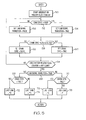
- FIG. 5 is a flow diagram representative of a software routine executed by the ECM of FIG. 2 for carrying out the method of this invention.
- the present invention is disclosed in the context of an eight-cylinder four-stroke internal combustion engine, generally designated by the reference numeral 10.
- the engine 10 includes a set of eight pistons 12 (only one of which is shown) which reciprocate in respective cylinders 14 and are connected to crankshaft 16.
- the crankshaft 16 is connected to the crank-wheel 18, which is mechanically coupled to a cam-wheel 20 by a belt or chain 21 so that the crank-wheel 18 and the cam-wheel 20 rotate synchronously.
- the cam-wheel 20 is connected to a camshaft 22, which opens and closes a cylinder intake valve 24 through a mechanical linkage 25 in coordination with the movement of piston 12.
- Intake air enters an intake manifold 26 through a throttle passage 27, and is delivered to each of the cylinders 14 via a respective intake runner 28 and intake valve 24.
- engine 10 includes many other component parts such as exhaust valves that are also conventional and known in the state of the art to be part of an operational engine.
- a microprocessor-based engine control module (ECM) 30 controls the timing of various engine cycle-related events (including fuel injection and spark timing, for example) based on a CRANK signal produced by a first sensor 32 responsive to the rotation of crank-wheel 18 and a CAM signal produced by a second sensor 34 responsive to the rotation of cam-wheel 20.
- the outer peripheries of crank-wheel 18 and cam-wheel 20 are toothed, and the sensors 32 and 34 are variable reluctance or similar sensors that produce electrical pulses corresponding to movement of the teeth.
- crank-wheel 18 is provided with a set of fifty-eight teeth and an 18° notch or gap, resulting in the CRANK signal depicted in Graph A of FIG. 1; and cam-wheel 20 is provided with a set of four width-encoded teeth, resulting in the CAM signal depicted in Graph B of FIG. 1.
- the CAM signal is traditionally decoded by evaluating the pattern of long and short pulse widths.
- CAM pulse #1 can be uniquely identified as a short pulse preceded by a long pulse.
- CAM pulse #2 can be uniquely identified as a short pulse preceded by a short pulse;
- CAM pulse #3 can be uniquely identified as a long pulse preceded by a short pulse;
- CAM pulse #4 can be uniquely identified as a long pulse preceded by a long pulse.
- Three state transitions of the CAM pulse are required to decode the CAM signal in this way, which corresponds to one full rotation of crank-wheel 18 or one-half rotation of cam-wheel 20.
- the decoding can require up to 540° of crankshaft rotation, depending on the initial engine position.
- the present invention is directed to a method of more quickly decoding the CAM signal by detecting the presence or absence of a CRANK signal sync pulse within an observation window defined with respect to a CAM signal pulse.
- the observation windows begin at a pulse transition of CAM signal and end after the crank-wheel 18 has rotated through a predetermined angle.
- the observation windows can be configured to begin subsequent to a pulse transition of CAM signal, or even prior to a pulse transition of CAM signal, so long as the CAM signal state and CRANK signal sync pulse can be detected during the observation window.
- Graphs A and B of FIG. 3 respectively reproduce the CRANK and CAM signals of FIG. 1, along with a set of observation windows 40-46.
- the observation windows 40-46 each begin at the falling edge of a CAM signal pulse, and each has a period equal to approximately 102° of crankshaft rotation (i.e., a rotation interval defined by 17 teeth of the crank-wheel 18).
- Observation window 40 begins at the falling edge of CAM pulse #1; observation window 42 begins at the falling edge of CAM pulse #2; observation window 44 begins at the falling edge of CAM pulse #3; and observation window 46 begins at the falling edge of CAM pulse #4.
- CRANK signal Since the CRANK signal has a sync pulse and CAM signal has width-encoded pulses (short-short-long-long in the illustrated embodiment), a unique combination of CAM signal transitions and CRANK signal sync pulses occurs in each of the observation windows.
- Observation window 40 contains no CAM signal transition and no CRANK signal sync pulse;
- observation window 42 contains a CAM signal transition and a CRANK signal sync pulse;
- observation window 44 contains a CAM signal transition but no CRANK signal sync pulse; and observation window 46 contains a CRANK signal sync pulse but no CAM signal transition.
- This pattern is illustrated in the table of FIG. 4, demonstrating that only one observation window is required to uniquely decode the CAM signal.
- the CRANK signal can be simultaneously decoded by applying the phase angle to the decoded CAM signal position.
- the cam decoding process can take anywhere from 102° of crankshaft rotation to 282° of crankshaft rotation.
- the minimum decoding interval of 102° is simply the observation window period, whereas the maximum decoding interval of 282° represents the case where 180° of crankshaft rotation transpire before a falling pulse edge of the CAM signal can be detected.
- This is in contrast to the traditional cam decoding method outlined above in reference to FIG. 1 where the minimum decoding interval is 360° of crankshaft rotation, and the maximum intervals is 540° of crankshaft rotation.
- the flow diagram of FIG. 5 represents an interrupt service routine executed by ECM 30 when the first falling pulse edge of the CAM signal is detected during engine cranking.
- the block 50 is first executed to reset an Observation Window Pulse Counter that counts pulses of the CRANK signal.
- the blocks 52, 54, 56, 58, 60 and 62 are then executed to monitor for a CAM signal pulse transition (specifically, a rising pulse edge) and a CRANK signal sync pulse.
- the presence or absence of a CAM signal transition is reflected by the state of a CAM SIGNAL TRANSITION flag, while the presence or absence of a CRANK signal sync pulse is reflected by the state of a CRANK SYNC flag.
- Block 64 compares the Observation Window Pulse Counter to a reference count such as 17 pulses, and requires re-execution of blocks 52-62 until the observation window period has expired. After expiration of the observation window period, the blocks 66, 68, 70, 72, 74, 76 and 78 are executed to perform the decode logic represented by the table of FIG. 4 based on the states of the CAM SIGNAL TRANSITION and CRANK SYNC flags, completing the routine.
- the method of the present invention significantly reduces the time required to decode a pulse width encoded CAM signal for a four-stroke internal combustion engine, enabling more prompt engine starting. While the present invention has been described with respect to the illustrated embodiment, it is recognized that numerous modifications and variations in addition to those mentioned herein will occur to those skilled in the art. For example, the method may be applied to engines having any number of cylinders, or cam-wheel and crank-wheel tooth patterns different than shown herein, and so on. Accordingly, it is intended that the invention not be limited to the disclosed embodiment, but that it have the full scope permitted by the language of the following claims.
Landscapes
- Engineering & Computer Science (AREA)
- Chemical & Material Sciences (AREA)
- Combustion & Propulsion (AREA)
- Mechanical Engineering (AREA)
- General Engineering & Computer Science (AREA)
- Combined Controls Of Internal Combustion Engines (AREA)
- Testing Of Engines (AREA)
Applications Claiming Priority (1)
| Application Number | Priority Date | Filing Date | Title |
|---|---|---|---|
| US11/493,806 US7366603B2 (en) | 2006-07-26 | 2006-07-26 | Method of decoding a CAM signal for an internal combustion engine |
Publications (2)
| Publication Number | Publication Date |
|---|---|
| EP1882839A2 true EP1882839A2 (fr) | 2008-01-30 |
| EP1882839A3 EP1882839A3 (fr) | 2013-12-18 |
Family
ID=38533177
Family Applications (1)
| Application Number | Title | Priority Date | Filing Date |
|---|---|---|---|
| EP07075557.4A Withdrawn EP1882839A3 (fr) | 2006-07-26 | 2007-07-04 | Procédé de décodage d'un signal d'arbre à came pour un moteur à combustion interne |
Country Status (2)
| Country | Link |
|---|---|
| US (1) | US7366603B2 (fr) |
| EP (1) | EP1882839A3 (fr) |
Cited By (1)
| Publication number | Priority date | Publication date | Assignee | Title |
|---|---|---|---|---|
| WO2012139805A1 (fr) | 2011-04-12 | 2012-10-18 | Robert Bosch Gmbh | Procédé pour déterminer une position initiale d'un mouvement cyclique |
Families Citing this family (9)
| Publication number | Priority date | Publication date | Assignee | Title |
|---|---|---|---|---|
| JP4274253B2 (ja) * | 2007-02-01 | 2009-06-03 | 株式会社デンソー | エンジン制御装置およびプログラム |
| WO2011150487A1 (fr) * | 2010-05-31 | 2011-12-08 | Blutip Power Technologies Ltd. | Procédé et système pour améliorer l'économie de carburant et maîtriser les émissions d'un moteur |
| KR102518658B1 (ko) * | 2018-07-30 | 2023-04-06 | 현대자동차주식회사 | 차량의 시동성능 향상 제어 방법 및 이를 포함하는 차량 |
| US11181016B2 (en) * | 2019-02-08 | 2021-11-23 | Honda Motor Co., Ltd. | Systems and methods for a crank sensor having multiple sensors and a magnetic element |
| US11162444B2 (en) * | 2019-02-08 | 2021-11-02 | Honda Motor Co., Ltd. | Systems and methods for a crank sensor having multiple sensors and a magnetic element |
| US11199426B2 (en) * | 2019-02-08 | 2021-12-14 | Honda Motor Co., Ltd. | Systems and methods for crankshaft tooth encoding |
| US11131567B2 (en) | 2019-02-08 | 2021-09-28 | Honda Motor Co., Ltd. | Systems and methods for error detection in crankshaft tooth encoding |
| US11959820B2 (en) | 2021-03-17 | 2024-04-16 | Honda Motor Co., Ltd. | Pulser plate balancing |
| USD1057753S1 (en) | 2022-06-04 | 2025-01-14 | Apple Inc. | Display screen or portion thereof with graphical user interface |
Family Cites Families (9)
| Publication number | Priority date | Publication date | Assignee | Title |
|---|---|---|---|---|
| US5079945A (en) * | 1991-01-23 | 1992-01-14 | Delco Electronics Corporation | Crankshaft direction of rotation detecting apparatus |
| JP3325154B2 (ja) * | 1995-04-21 | 2002-09-17 | 三菱電機株式会社 | 内燃機関制御装置 |
| US6721648B2 (en) * | 1999-11-02 | 2004-04-13 | Autotronic Controls Corporation | Method and apparatus for controlling a motorcycle engine |
| FR2802242B1 (fr) * | 1999-12-10 | 2002-05-10 | Siemens Automotive Sa | Procede de determination de la position moteur et dispositif correspondant |
| JP3508676B2 (ja) * | 2000-02-01 | 2004-03-22 | 株式会社デンソー | エンジン制御装置 |
| JP4151279B2 (ja) * | 2002-02-26 | 2008-09-17 | 株式会社デンソー | エンジン制御装置 |
| DE10323486B4 (de) * | 2003-05-23 | 2012-10-25 | Robert Bosch Gmbh | Verfahren zum Betreiben einer Brennkraftmaschine, insbesondere in einem Kraftfahrzeug |
| US7069140B2 (en) * | 2004-06-30 | 2006-06-27 | General Electric Company | Engine operation without cam sensor |
| FR2876738B1 (fr) * | 2004-10-20 | 2009-09-25 | Siemens Vdo Automotive Sas | Procede pour determiner le phasage d'un moteur a combustion interne |
-
2006
- 2006-07-26 US US11/493,806 patent/US7366603B2/en active Active
-
2007
- 2007-07-04 EP EP07075557.4A patent/EP1882839A3/fr not_active Withdrawn
Cited By (2)
| Publication number | Priority date | Publication date | Assignee | Title |
|---|---|---|---|---|
| WO2012139805A1 (fr) | 2011-04-12 | 2012-10-18 | Robert Bosch Gmbh | Procédé pour déterminer une position initiale d'un mouvement cyclique |
| DE102011007174A1 (de) | 2011-04-12 | 2012-10-18 | Robert Bosch Gmbh | Vefahren zur Bestimmung einer Anfangsposition einer zyklischen Bewegung |
Also Published As
| Publication number | Publication date |
|---|---|
| US7366603B2 (en) | 2008-04-29 |
| US20080027622A1 (en) | 2008-01-31 |
| EP1882839A3 (fr) | 2013-12-18 |
Similar Documents
| Publication | Publication Date | Title |
|---|---|---|
| EP1882839A2 (fr) | Procédé de décodage d'un signal d'arbre à came pour un moteur à combustion interne | |
| JP3261212B2 (ja) | 内燃機関の燃料噴射装置のための気筒判別方法 | |
| US8914218B2 (en) | Four-stroke cycle internal combustion engine and method of identifying cylinder of four-stroke cycle internal combustion engine | |
| US9273656B2 (en) | Method and control unit for controlling an internal combustion engine | |
| EP0846852B1 (fr) | Méthode de synchronisation d'un moteur à combustion sans détecteur de position d'arbre à came | |
| EP1882838A2 (fr) | Procédé pour déterminer la position d'arrêt d'un moteur à combustion interne | |
| JP2006257958A (ja) | カム位相センサ,可変バルブタイミング機構の制御装置及び可変バルブタイミング機構の制御方法 | |
| JP2004156530A (ja) | 内燃機関のクランク角度検出装置 | |
| CN108397304B (zh) | 事件驱动下的电喷si发动机喷气点火同步控制方法 | |
| KR20130025397A (ko) | 분사 제어 방법 | |
| CN1671957B (zh) | 发动机控制装置 | |
| EP2085597B1 (fr) | Dispositif de commande d'injection de carburant pour moteur à combustion interne | |
| US6494086B1 (en) | System for detecting the operative strokes of an internal combustion reciprocating engine | |
| US6588404B1 (en) | Redundant sensor with cylinder shutdown | |
| CN1298986C (zh) | 一种四缸机电控发动机凸轮轴及发动机相位检测方法 | |
| JPWO2003036068A1 (ja) | エンジン制御装置 | |
| JP6645302B2 (ja) | 内燃機関の制御装置 | |
| JP2004245162A (ja) | 内燃機関制御装置および内燃機関のクランク角信号処理方法 | |
| CN1884810B (zh) | 判定发动机中的活塞位置的装置和方法 | |
| JPH11351050A (ja) | エンジン制御装置 | |
| KR101793078B1 (ko) | 캠 센서가 없는 차량엔진 동기 설정의 에러검출 방법 | |
| US8423268B2 (en) | Device for controlling the operation of an internal combustion engine, with improved rephasing of injection events | |
| JP3782884B2 (ja) | エンジンのクランク角検出装置 | |
| JP4313733B2 (ja) | エンジンの気筒判定装置 | |
| JP2002130005A (ja) | エンジンの制御情報検出装置 |
Legal Events
| Date | Code | Title | Description |
|---|---|---|---|
| PUAI | Public reference made under article 153(3) epc to a published international application that has entered the european phase |
Free format text: ORIGINAL CODE: 0009012 |
|
| AK | Designated contracting states |
Kind code of ref document: A2 Designated state(s): AT BE BG CH CY CZ DE DK EE ES FI FR GB GR HU IE IS IT LI LT LU LV MC MT NL PL PT RO SE SI SK TR |
|
| AX | Request for extension of the european patent |
Extension state: AL BA HR MK YU |
|
| PUAL | Search report despatched |
Free format text: ORIGINAL CODE: 0009013 |
|
| AK | Designated contracting states |
Kind code of ref document: A3 Designated state(s): AT BE BG CH CY CZ DE DK EE ES FI FR GB GR HU IE IS IT LI LT LU LV MC MT NL PL PT RO SE SI SK TR |
|
| AX | Request for extension of the european patent |
Extension state: AL BA HR MK RS |
|
| RIC1 | Information provided on ipc code assigned before grant |
Ipc: F02D 41/06 20060101ALN20131112BHEP Ipc: F02D 41/00 20060101AFI20131112BHEP |
|
| AKY | No designation fees paid | ||
| REG | Reference to a national code |
Ref country code: DE Ref legal event code: R108 |
|
| REG | Reference to a national code |
Ref country code: DE Ref legal event code: R108 Effective date: 20140827 |
|
| STAA | Information on the status of an ep patent application or granted ep patent |
Free format text: STATUS: THE APPLICATION IS DEEMED TO BE WITHDRAWN |
|
| 18D | Application deemed to be withdrawn |
Effective date: 20140619 |