EP1883145A2 - Armature tournante - Google Patents
Armature tournante Download PDFInfo
- Publication number
- EP1883145A2 EP1883145A2 EP07005317A EP07005317A EP1883145A2 EP 1883145 A2 EP1883145 A2 EP 1883145A2 EP 07005317 A EP07005317 A EP 07005317A EP 07005317 A EP07005317 A EP 07005317A EP 1883145 A2 EP1883145 A2 EP 1883145A2
- Authority
- EP
- European Patent Office
- Prior art keywords
- coil
- bobbin
- stator
- winding portion
- coil winding
- Prior art date
- Legal status (The legal status is an assumption and is not a legal conclusion. Google has not performed a legal analysis and makes no representation as to the accuracy of the status listed.)
- Withdrawn
Links
Images



Classifications
-
- H—ELECTRICITY
- H02—GENERATION; CONVERSION OR DISTRIBUTION OF ELECTRIC POWER
- H02K—DYNAMO-ELECTRIC MACHINES
- H02K3/00—Details of windings
- H02K3/46—Fastening of windings on the stator or rotor structure
- H02K3/52—Fastening salient pole windings or connections thereto
- H02K3/521—Fastening salient pole windings or connections thereto applicable to stators only
- H02K3/522—Fastening salient pole windings or connections thereto applicable to stators only for generally annular cores with salient poles
-
- H—ELECTRICITY
- H02—GENERATION; CONVERSION OR DISTRIBUTION OF ELECTRIC POWER
- H02K—DYNAMO-ELECTRIC MACHINES
- H02K2203/00—Specific aspects not provided for in the other groups of this subclass relating to the windings
- H02K2203/09—Machines characterised by wiring elements other than wires, e.g. bus rings, for connecting the winding terminations
-
- H—ELECTRICITY
- H02—GENERATION; CONVERSION OR DISTRIBUTION OF ELECTRIC POWER
- H02K—DYNAMO-ELECTRIC MACHINES
- H02K2203/00—Specific aspects not provided for in the other groups of this subclass relating to the windings
- H02K2203/12—Machines characterised by the bobbins for supporting the windings
Definitions
- the present invention relates to a rotating armature.
- the rotating armature it is preferable to execute a regular winding without disarranging a winding position of the coil during winding of the coil around the coil winding portion, to maximize a space occupied by a coil winding (a line occupying rate) with respect to a bobbin, and achieve a downsizing of the stator.
- a coil engagement groove is provided in a side surface of a rectangular tube in the coil winding portion of the bobbin, thereby regulating the winding position of the coil, however, a resin forming mold of the bobbin becomes complicated, and it is hard to manufacture the bobbin. Further, in the case that the coil engagement groove is provided in the side surface of the rectangular tube in the coil winding portion, the coil winding position is constrained unnecessarily, and a coil winding workability is lowered.
- An object of the present invention is to improve a coil winding workability by achieving a regular winding of a coil while simplifying a formability of a bobbin, in a rotating armature.
- the present invention relates to a rotating armature, comprising: a resin bobbin around a core constituting a stator; a coil wound around a rectangular tubular coil winding portion of the bobbin; and a coil engagement groove provided only in a corner portion of a rectangular tube in the coil winding portion of the bobbin.
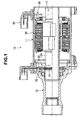
- a DC brushless motor 10 corresponding to a rotating armature in accordance with the present invention is structured, as shown in FIG. 1, such that an end housing 12 is attached to one end of a stator assembly 11, and a rotor assembly 13 is rotatably supported to the stator assembly 11 and an inner portion of the end housing 12.
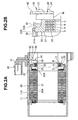
- the stator assembly 11 is structured, as shown in FIGS. 2A to 3B, such that a sub assembly of a cylindrical stator 20 and a terminal 30 is stored in an inner periphery of a yoke integrally formed with the housing 11A, and a coupler 40 attached to the housing 11A is connected to the terminal 30.
- the stator 20 is structured, as shown in FIGS. 4A and 4B, such that a plurality of, for example, four in each of U-phase, V-phase and W-phase (totally twelve) core sub assemblies 20A in the present embodiment, fitted to the inner periphery of the housing 11A are arranged adjacently on a circumference.
- the core sub assembly 20A is structured by laminating a plurality of cores 21 constituted by silicon steel plates, attaching a resin bobbin 22 to the laminated core 21 and winding respective motor coils 23 forming three phases constituted by the U-phase, the V-phase and the W-phase around a coil winding portion 22A of the resin bobbin 22, as shown in FIGS. 5A and 5B.
- Each of the motor coils 23 is structured such that both ends constituted by a wind starting end and a wind terminating end are respectively set to a coil terminal 23A and a common terminal 23B, and these terminals 23A and 23B are extended to an outer side from one end side of the coil winding portion 22A of the resin bobbin 22.
- the resin bobbin 22 is provided with a terminal mounting portion 22B (a concave portion) protruding in an axial direction of the housing 11A along an inner periphery of the housing 11A, in one end side of the coil winding portion 22A.
- the terminal 30 is attached to the resin bobbin 22 so as to be positioned in a peripheral direction, an axial direction and a diametrical direction by being embedded in a resin portion 31 formed by the resin mold so as to be integrated, in a state in which respective ring main bodies 32 of three bus rings A to C and the neutral bus ring D are arranged in parallel in an axial direction, and locking mounting hooks 31A provided at a plurality of positions in an outer periphery of the resin portion 31 to a concave portion of the terminal mounting portion 22B of the resin bobbin 22, as shown in FIGS. 2A to 4B.
- the ring main bodies 32 of the bus rings A to C are formed in a C-shaped form so as to be partly cut in the peripheral direction, and the ring main body 32 of the neutral bus ring D is formed in an annular shape continuously formed in the peripheral direction.
- Each of the bus rings A to D is connected to the ring main body 32 thereof so as to extend to an outer side in the radial direction of the ring main body 32, and is provided with a terminal portion 33 protruding to an outer portion of the resin portion 31, as shown in FIGS. 2A to 4B.
- the bus ring A is provided with four terminal portions 33 to which the coil terminals 23A of four U-phase motor coils 23 are connected, in the present embodiment.
- the bus ring B is provided with four terminal portions 33 to which the coil terminals 23A of four V-phase motor coils 23 are connected, in the present embodiment.
- the bus ring C is provided with four terminal portions 33 to which the coil terminals 23A of four W-phase motor coils 23 are connected, in the present embodiment.
- the neutral bus ring D is provided with twelve terminal portions 33 to which the common terminals 23B of twelve motor coils 23 are connected, in the present embodiment. Accordingly, each of the motor coils 23 is star connected by connecting each of the terminal portions 33 connected to the ring main body 32 of each of the bus rings A to C of the terminal 30 and protruding from the resin portion 31 to the coil terminal 23A of each of the U-phase, V-phase and W-phase motor coils 23 of the stator 20, and connecting the terminal portion 33 connected to the ring main body 32 of the neutral bus ring D and protruding from the resin portion 31 to the common terminal 23B of each of the motor coils 23.
- Each of the bus rings A to C is provided with an external portion connecting connection portion 34 which is connected to the ring main body 32 thereof so as to be folded and stand up in an axial perpendicular direction of the ring main body 32 from one end in a peripheral direction of the ring main body 32, and protrudes to an outer portion of the resin portion 31 as shown in FIGS. 2A to 4B.
- connection portions 34 of the bus rings A to C are arranged in parallel to each other.
- the coupler 40 is structured, as shown in FIGS. 2A to 3B, such that U-phase, V-phase and W-phase connection terminals 42 connected to a control circuit in an external portion are embedded in a resin body 41 screwed into the outer surface of the housing 11A.
- Each of the U-phase, V-phase and W-phase connection terminals 42 of the coupler 40 is inserted to an inner portion of the housing 11A, and is connected to the connection portion 34 of each of the bus rings A to C of the terminal 30.
- Each of the connection terminals 42 is inserted to each of the connection portions 34 so as to be mated, and welded.
- each of the bus rings A to C is provided with a heat radiation portion 36 positioned in an outer side of the resin portion 31 and exposing to the outer side of the resin portion 31, between the ring main body 32 molded in the resin portion 31 and the connection portion 34, as shown in FIGS. 2A to 4B.
- each of the bus rings A to C has a plate-shaped piece 35 which is obtained by forming the ring main body 32 in a C-shaped plate form, is bent in an axial perpendicular direction of the ring main body 32 from one end in the peripheral direction of each of the ring main bodies 32 so as to stand up, and protrudes toward the outer side in the axial direction from the resin portion 31.
- the terminal 30 is structured such that a root side portion with respect to the resin portion 31 of the plate-shaped piece 35 of each of the bus rings A to C is formed as the heat radiation portion 36 extending in the radial direction of the ring main body 32 so as to be long. Further, a leading end side portion of the plate-shaped piece 35, a small piece portion in the leading end lower side protruding toward the outer side in the axial direction of the ring main body 32 from the center side end in the radial direction of the ring main body 32 in the plate-shaped piece 35 in the present embodiment is formed as the connection portion 34. In this case, the terminal 30 is provided with a positioning portion 37 for the connection terminal 42 of the coupler 40, in the leading end upper side of the plate-shaped piece 35.
- the motor 10, as shown in FIG. 1, has a resolver 50 constituted by a resolver rotor portion 51 and a resolver stator portion 52.
- the resolver rotor portion 51 rotating together with the rotating shaft 13A is attached to an outer periphery of the rotating shaft 13A of the rotor assembly 13.
- the resolver stator portion 52 is attached to a side of the stator 20, that is, an inner periphery of the end housing 12.
- the resolver stator 52 is arranged in such a manner as to surround the resolver rotor portion 51, and detects a rotational position of the rotating shaft 13A on the basis of a change of a reluctance generated with respect to the resolver rotor portion 51 caused by the rotation.
- a predetermined pattern of current is supplied to each of the U-phase, V-phase and W-phase motor coils 23 of the stator 20 via the coupler 40 and the terminal 30 by the external control circuit in correspondence to the detected rotational position of the rotating shaft 13A, and the drive of the motor 10 is controlled.
- the bobbin 22 constituting the core sub assembly 20A of the stator 20 is formed by confronting two bobbin elements 60 and 60 divided into two in a longitudinal direction (a direction along a center axis of the stator 20) of the core sub assembly 20A so as to integrate.
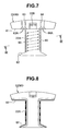
- the bobbin elements 60 and 60 of the bobbin 22 form the rectangular tubular coil winding portion 22A, attaches the rectangular tube of the coil winding portion 22A to the core 21, and winds the coil 23 around upper and lower surfaces and both side surfaces between a base end wall 61 and a leading end collar 62 of the coil winding portion 22A, as shown in FIGS. 6 to 8.
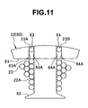
- the stator 20 is provided in a concave manner with a wind starting coil insertion groove 63 and a wind terminating coil insertion groove 64 extending to an outer side while being orthogonal to the base end wall 61 so as to be in parallel, in an outer peripheral side than the base end wall 61 of the coil winding portion 22A (in an outer peripheral side than the coil winding portion 22A in the diametrical direction of the stator 20), in an end surface of the one of the bobbin element 60 to which the terminal 30 is attached, from the bobbin elements 60 and 60 forming the bobbin 22. Further, the wind starting (the coil terminal 23A) and the wind terminating (the common terminal 23B) of the coil 23 are respectively inserted to the coil insertion grooves 63 and 64.
- the common terminal 23B is connected to the terminal portion 33 of the bus ring D of the terminal 30 mentioned above through the coil insertion groove 64 in the outer peripheral side of the coil winding portion 22A.
- the coil terminal 23A is connected to the terminal portion 33 in each of the bus rings A to C of the terminal 30 mentioned above through the coil insertion groove 63 in the outer peripheral side of the coil winding portion 22A.
- the bobbin elements 60 and 60 forming the bobbin 22 are provided with coil engagement grooves 65 only in four corner portions on the coil winding path of the rectangular tube in the coil winding portion 22A, as shown in FIGS. 7, 9 and 10.
- the winding position of the coil 23 is engaged with the coil engagement groove 65 provided in the corner portion of the rectangular tube in the coil winding portion 22A so as to be position regulated, and is regular wound.
- the coil winding position of the coil 23 is positioned only by the corner portions of the rectangular tube, the coil winding position is not unnecessarily constrained. Accordingly, the coil winding workability is improved.
- the coil come-off preventing locking portions 63A and 64A are provided in the coil insertion grooves 63 and 64 formed in a concave manner in one bobbin element 60 forming the bobbin 22 as mentioned above.
- the coil come-off preventing locking portion 63A is provided in a concave-manner approximately in an entire region in a depth direction of the coil insertion groove 63, in both side walls of the groove close to the base end wall 61 in a groove extending direction of the coil insertion groove 63, in the bobbin element 60 of the bobbin 22.
- the wind starting coil terminal 23A of the coil 23 wound around the coil winding portion 22A is pinched by the coil come-off preventing locking portion 63A in a state of being inserted to the coil insertion grove 63 so as to be prevented from coming off, as shown in FIG.
- the coil come-off preventing locking portion 63A may be structured such as to be provided in a convex manner only in an open edge side in the depth direction of the coil insertion groove 63, in both side walls of the groove close to the base end wall 61 in the groove extending direction of the coil insertion groove 63, and prevent the coil terminal 23A from coming off from the coil insertion groove 63 by pressing the coil terminal 23A of the coil 23 inserted to the coil insertion groove 63 from the open edge side of the coil insertion groove 63.
- the coil come-off preventing locking portion 64A is provided in a concave manner approximately in an entire region in the depth direction of the coil insertion groove 64, in both side walls of the groove close to the base end wall 61 in the groove extending direction of the coil insertion groove 64, in the bobbin element 60 of the bobbin 22.
- the wind terminating common terminal 23B of the coil 23 wound around the coil winding portion 22A is pinched to the coil come-off preventing locking portion 64A in a state of being inserted to the coil insertion groove 64 so as to be prevented from coming off, as shown in FIG.
- the coil come-off preventing locking portion 64A may be structured such as to be provided in a convex manner only in an open edge side in a depth direction of the coil insertion groove 64, in both side walls of the groove close to the base end wall 61 in the groove extending direction of the coil insertion groove 64, and prevent the common terminal 23B from coming off from the coil insertion groove 64 by pressing the common terminal 23B of the coil 23 inserted to the coil insertion groove 64 from the open edge side of the coil insertion groove 64.
Landscapes
- Engineering & Computer Science (AREA)
- Power Engineering (AREA)
- Insulation, Fastening Of Motor, Generator Windings (AREA)
Applications Claiming Priority (1)
| Application Number | Priority Date | Filing Date | Title |
|---|---|---|---|
| JP2006205408A JP2008035601A (ja) | 2006-07-27 | 2006-07-27 | 回転電機 |
Publications (2)
| Publication Number | Publication Date |
|---|---|
| EP1883145A2 true EP1883145A2 (fr) | 2008-01-30 |
| EP1883145A3 EP1883145A3 (fr) | 2008-07-16 |
Family
ID=38626406
Family Applications (1)
| Application Number | Title | Priority Date | Filing Date |
|---|---|---|---|
| EP07005317A Withdrawn EP1883145A3 (fr) | 2006-07-27 | 2007-03-14 | Armature tournante |
Country Status (3)
| Country | Link |
|---|---|
| US (1) | US20080024029A1 (fr) |
| EP (1) | EP1883145A3 (fr) |
| JP (1) | JP2008035601A (fr) |
Cited By (2)
| Publication number | Priority date | Publication date | Assignee | Title |
|---|---|---|---|---|
| WO2010006679A3 (fr) * | 2008-07-17 | 2010-11-25 | Sew-Eurodrive Gmbh & Co. Kg | Moteur électrique |
| WO2017078937A3 (fr) * | 2015-11-05 | 2017-08-03 | Globe Motors, Inc. | Stator enroulé avec système d'isolation |
Families Citing this family (11)
| Publication number | Priority date | Publication date | Assignee | Title |
|---|---|---|---|---|
| JP5273448B2 (ja) * | 2008-06-17 | 2013-08-28 | 日本電産株式会社 | モータ |
| JP5453880B2 (ja) * | 2009-03-31 | 2014-03-26 | 日本電産株式会社 | モータ |
| CN102428624A (zh) * | 2009-07-17 | 2012-04-25 | 大金工业株式会社 | 定子、电动机以及压缩机 |
| JP5813463B2 (ja) * | 2011-11-02 | 2015-11-17 | 株式会社東芝 | 回転電機の固定子、固定子用ホルダ、回転電機、及び自動車 |
| JP5641366B2 (ja) * | 2012-01-25 | 2014-12-17 | 株式会社デンソー | ステータ、及びステータの製造方法 |
| JP5652671B2 (ja) * | 2012-05-22 | 2015-01-14 | 株式会社デンソー | モータ、および、それを用いた燃料ポンプ |
| CN104137392B (zh) * | 2012-06-21 | 2017-09-22 | 三菱电机株式会社 | 旋转电机 |
| WO2015005050A1 (fr) * | 2013-07-08 | 2015-01-15 | 日産自動車株式会社 | Structure d'isolant pour une machine dynamoélectrique |
| KR102410397B1 (ko) * | 2015-06-30 | 2022-06-17 | 엘지이노텍 주식회사 | 인슐레이터 및 이를 포함하는 모터 |
| CN111614186A (zh) * | 2020-06-15 | 2020-09-01 | 无锡威孚高科技集团股份有限公司 | 一种快插式定子集中绕组齿形绝缘骨架 |
| WO2023232532A1 (fr) * | 2022-06-03 | 2023-12-07 | Robert Bosch Gmbh | Rotor de machine électrique |
Family Cites Families (6)
| Publication number | Priority date | Publication date | Assignee | Title |
|---|---|---|---|---|
| JP2975902B2 (ja) * | 1997-01-31 | 1999-11-10 | 株式会社東芝 | 回転電機のステータ |
| JP3505347B2 (ja) * | 1997-04-24 | 2004-03-08 | 株式会社東芝 | 直流モータ |
| JP3498129B2 (ja) * | 2001-05-24 | 2004-02-16 | 三菱電機株式会社 | 回転電機 |
| JP4826718B2 (ja) * | 2004-07-27 | 2011-11-30 | 日本電産株式会社 | モータ用の電機子およびモータ |
| US20060071569A1 (en) * | 2004-10-04 | 2006-04-06 | Stewart William P | Stator end caps and methods for positioning the lead and exit ends of the stator windings |
| JP4428652B2 (ja) * | 2004-10-12 | 2010-03-10 | アスモ株式会社 | インシュレータ、電動機、及び巻線の巻回方法 |
-
2006
- 2006-07-27 JP JP2006205408A patent/JP2008035601A/ja active Pending
-
2007
- 2007-03-14 EP EP07005317A patent/EP1883145A3/fr not_active Withdrawn
- 2007-03-17 US US11/687,643 patent/US20080024029A1/en not_active Abandoned
Cited By (6)
| Publication number | Priority date | Publication date | Assignee | Title |
|---|---|---|---|---|
| WO2010006679A3 (fr) * | 2008-07-17 | 2010-11-25 | Sew-Eurodrive Gmbh & Co. Kg | Moteur électrique |
| CN102099985A (zh) * | 2008-07-17 | 2011-06-15 | 索尤若驱动有限及两合公司 | 电机 |
| US8638019B2 (en) | 2008-07-17 | 2014-01-28 | Sew-Eurodrive Gmbh & Co. Kg | Electric motor |
| CN102099985B (zh) * | 2008-07-17 | 2014-04-16 | 索尤若驱动有限及两合公司 | 电机 |
| WO2017078937A3 (fr) * | 2015-11-05 | 2017-08-03 | Globe Motors, Inc. | Stator enroulé avec système d'isolation |
| US10910901B2 (en) | 2015-11-05 | 2021-02-02 | Globe Motors, Inc. | Wound stator with insulation system forming a wire guide for a winding operation |
Also Published As
| Publication number | Publication date |
|---|---|
| JP2008035601A (ja) | 2008-02-14 |
| US20080024029A1 (en) | 2008-01-31 |
| EP1883145A3 (fr) | 2008-07-16 |
Similar Documents
| Publication | Publication Date | Title |
|---|---|---|
| EP1883145A2 (fr) | Armature tournante | |
| EP1881584B1 (fr) | Borne pour induit tournant | |
| EP1883146A2 (fr) | Armature tournante | |
| JP5176283B2 (ja) | 回転電機のバスバー絶縁構造 | |
| JP5489698B2 (ja) | インシュレータ、回転電機および回転電機の製造方法 | |
| US10439453B2 (en) | Stator | |
| EP2833520B1 (fr) | Stator | |
| JP2005080461A (ja) | クローポール型ステッピングモータのモータ構造 | |
| JP3711996B2 (ja) | 電動機の固定子 | |
| JP2010154701A (ja) | 回転電機用ターミナル | |
| CN107528401B (zh) | 定子及马达 | |
| EP2738916B1 (fr) | Stator d'un moteur électrique comprenant une isolation de bobine | |
| JP2017163825A (ja) | モータ及びそのステータ | |
| JP5233630B2 (ja) | ステータ、回転電機、ステータの製造方法および回転電機の製造方法 | |
| US8823240B2 (en) | Stator and rotating electrical machine | |
| CN113572278A (zh) | 无刷电机定子和无刷电机 | |
| CN106300711A (zh) | 用于电机的定子、电机、车辆和制造方法 | |
| JP4847727B2 (ja) | 回転電機 | |
| JP4847728B2 (ja) | 回転電機 | |
| JP6233217B2 (ja) | 回転電機のステータ | |
| JP5513163B2 (ja) | スロットレスモータ | |
| KR20220007448A (ko) | 모터용 버스바 유닛 | |
| JP2010239825A (ja) | モータ | |
| JP4875857B2 (ja) | 回転電機 | |
| JP7109550B2 (ja) | 回転電機 |
Legal Events
| Date | Code | Title | Description |
|---|---|---|---|
| PUAI | Public reference made under article 153(3) epc to a published international application that has entered the european phase |
Free format text: ORIGINAL CODE: 0009012 |
|
| AK | Designated contracting states |
Kind code of ref document: A2 Designated state(s): AT BE BG CH CY CZ DE DK EE ES FI FR GB GR HU IE IS IT LI LT LU LV MC MT NL PL PT RO SE SI SK TR |
|
| AX | Request for extension of the european patent |
Extension state: AL BA HR MK YU |
|
| PUAL | Search report despatched |
Free format text: ORIGINAL CODE: 0009013 |
|
| AK | Designated contracting states |
Kind code of ref document: A3 Designated state(s): AT BE BG CH CY CZ DE DK EE ES FI FR GB GR HU IE IS IT LI LT LU LV MC MT NL PL PT RO SE SI SK TR |
|
| AX | Request for extension of the european patent |
Extension state: AL BA HR MK RS |
|
| 17P | Request for examination filed |
Effective date: 20081024 |
|
| AKX | Designation fees paid |
Designated state(s): DE GB |
|
| 17Q | First examination report despatched |
Effective date: 20100819 |
|
| STAA | Information on the status of an ep patent application or granted ep patent |
Free format text: STATUS: THE APPLICATION IS DEEMED TO BE WITHDRAWN |
|
| 18D | Application deemed to be withdrawn |
Effective date: 20121002 |