EP1883164B1 - Drahtlose Kommunikationsvorrichtung für den Empfang eines mobilen Rundfunksignals sowie zum Senden/Empfangen eines Bluetooth-Signals mit Einzelantenne - Google Patents
Drahtlose Kommunikationsvorrichtung für den Empfang eines mobilen Rundfunksignals sowie zum Senden/Empfangen eines Bluetooth-Signals mit Einzelantenne Download PDFInfo
- Publication number
- EP1883164B1 EP1883164B1 EP07002064A EP07002064A EP1883164B1 EP 1883164 B1 EP1883164 B1 EP 1883164B1 EP 07002064 A EP07002064 A EP 07002064A EP 07002064 A EP07002064 A EP 07002064A EP 1883164 B1 EP1883164 B1 EP 1883164B1
- Authority
- EP
- European Patent Office
- Prior art keywords
- signal
- dmb
- band
- pass filter
- bluetooth
- Prior art date
- Legal status (The legal status is an assumption and is not a legal conclusion. Google has not performed a legal analysis and makes no representation as to the accuracy of the status listed.)
- Ceased
Links
Images


Classifications
-
- H—ELECTRICITY
- H04—ELECTRIC COMMUNICATION TECHNIQUE
- H04B—TRANSMISSION
- H04B1/00—Details of transmission systems, not covered by a single one of groups H04B3/00 - H04B13/00; Details of transmission systems not characterised by the medium used for transmission
- H04B1/38—Transceivers, i.e. devices in which transmitter and receiver form a structural unit and in which at least one part is used for functions of transmitting and receiving
-
- H—ELECTRICITY
- H04—ELECTRIC COMMUNICATION TECHNIQUE
- H04H—BROADCAST COMMUNICATION
- H04H40/00—Arrangements specially adapted for receiving broadcast information
- H04H40/18—Arrangements characterised by circuits or components specially adapted for receiving
-
- H—ELECTRICITY
- H04—ELECTRIC COMMUNICATION TECHNIQUE
- H04B—TRANSMISSION
- H04B1/00—Details of transmission systems, not covered by a single one of groups H04B3/00 - H04B13/00; Details of transmission systems not characterised by the medium used for transmission
- H04B1/06—Receivers
- H04B1/16—Circuits
- H04B1/18—Input circuits, e.g. for coupling to an antenna or a transmission line
-
- H—ELECTRICITY
- H04—ELECTRIC COMMUNICATION TECHNIQUE
- H04B—TRANSMISSION
- H04B1/00—Details of transmission systems, not covered by a single one of groups H04B3/00 - H04B13/00; Details of transmission systems not characterised by the medium used for transmission
- H04B1/38—Transceivers, i.e. devices in which transmitter and receiver form a structural unit and in which at least one part is used for functions of transmitting and receiving
- H04B1/40—Circuits
- H04B1/44—Transmit/receive switching
Definitions
- the present invention relates to a mobile broadcasting technology, and more particularly, to a wireless communication device for receiving a mobile broadcasting signal and transmitting/receiving a Bluetooth@ signal with a single antenna.
- Mobile multimedia broadcasting is a new service that combines with a mobile communication technology, utilizing the advantages of both broadcasting and mobile communication.
- DVB-H Digital Video Broadcasting Handheld
- MediaFLO Asatellitedigital multimedia broadcasting (S-DMB) technology in Korea has commenced commercialization.
- S-DMB Asatellitedigital multimedia broadcasting
- T-DMB The world's first terrestrial DMB (T-DMB) broadcasting service has also been launched in Korea based on the Eureka-147 standard.
- DMB refers to a broadcasting service that provides a user with a digitally modulated multimedia (audio-video) signal.
- the DMB enables the user to view diverse multimedia broadcasts through a receiver having a non-directional receiving antenna even while the user is in motion.
- Development of a receiver for receiving DMB services is essential for commercialization of DMB services. Active development of a wide variety of DMB receivers and terminals contributes to commercialization of DMB services.
- DMB broadcast signals can be received through a dedicated DMB receiver as well as a portable or in-vehicle terminal supporting the function to receive DMB services.
- the DMB receiving function is currently embedded within various types of terminals such as mobile phones, notebook personal computers, personal digital assistants (PDAs), portable multimedia players (PMPs), pedestrian navigation systems and car navigation systems.
- PDAs personal digital assistants
- PMPs portable multimedia players
- pedestrian navigation systems and car navigation systems.
- Wireless headsets enable a wearer to conveniently listen to audio files using Bluetooth@ designed for short-range communication.
- the Bluetooth® short-range standard offers bi-directional wireless communication between two or more devices within a range of up to 10m by wirelessly connecting the devices.
- Bluetooth® operates at 2. 4 GHz frequency band while DMB uses different frequency bands.
- S-DMB operates at a frequency band of 2.63 to 2.6555 GHz.
- T-DMB operates at frequency bands of 174 to 240MHz and 1.452 to 1.492 GHz.
- a conventional DMB receiver simultaneously using the Bluetooth@ signal and DMB signal at different frequency bands requires two discrete antennas.
- WO 03/088510 A1 discloses a terminal able to receive data from a broadcast station and to participate in a wireless network using a single antenna and a diplexer.
- an object of the present invention is to provide a system according to claim 1.
- the DMB signal may be a terrestrial Digital Multimedia Broadcasting (T-DMB) signal and the DMB module may be a T-DMB module.
- the first band-pass filter may be a low-pass filter (LPF) and the second band-pass filter may be a high-pass filter (HPF).
- LPF low-pass filter
- HPF high-pass filter
- the T-DMB signal may have two different types of signals having first and second frequency bands, respectively.
- the wireless communication device may further include a third and a fourth band-pass filter connected between the LPF and the T-DMB module.
- the third band-pass filter passes the T-DMB signal from the first frequency band.
- the fourth band-pass filter passes the T-DMB signal from the second frequency band.
- the T-DMB signal may have a band-3 signal and an L-band signal.
- the wireless communication device may further include a band-3 filter and an L-band filter connected between the LPF and the T-DMB module.
- the band-3 filter and the L-band filter respectively pass the band-3 signal and the L-band signal of the T-DMB signal.
- the DMB signal may be a satellite DMB (S-DMB) signal and the mobile broadcasting module may be an S-DMB module.
- the first band-pass filter is an HPF and the second band-pass filter is an LPF.
- FIG. 1 is a diagram of a mobile broadcasting system to which the present invention is applied.
- a DMB transmission center 300 transmits a DMB signal received from a broadcasting station (not shown).
- a wireless communication device 100 e.g. a DMB receiver, receives a DMB signal from the DMB transmission center 300 and outputs video and audio data through signal processing.
- the wireless communication device 100 is not limited to a DMB receiver, and may be another portable or in-vehicle terminal having a DMB reception function.
- a headset 200 communicates with the wireless communication device 100 using Bluetooth® to receive the audio data of DMB data output from the wireless communication device 100.
- FIG. 1 shows the headset 200 and the wireless communication device 100 as separate elements for convenience, the headset 200 may be integrated into the wireless communication device 100.
- the system shown in FIG. 1 is a T-DMB system. If the mobile broadcasting system of FIG. 1 is an S-DMB system, it further requires a gap filler and a broadcasting satellite receiving a DMB signal from the DMB transmission center 300 and transmitting the DMB signal to a ground station.
- a conventional wireless communication device requires two separate antennas, i.e. an antenna for receiving a DMB signal and an antenna for transmitting/receiving a Bluetooth@ signal.
- the wireless communication device 100 receives a DMB signal and transmits or receives a Bluetooth® signal through a single antenna, which is possible by changing the front end configuration.
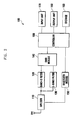
- FIG. 2 is a block diagram of the wireless communication device 100 according to the present invention.
- the wireless communication device 100 is a receiver that receives a mobile broadcasting signal through a single antenna Ant.
- the wireless communication device 100 is a dedicated DMB receiver receiving a T-DMB signal or portable or in-vehicle terminal.
- the wireless communication device 100 may be a receiver or terminal receiving a satellite DMB signal or other types of mobile broadcasting signals.
- the wireless communication device 100 includes a diplexer 110, a band-3 filter 120, an L-band filter 130, a DMB module 140, a Bluetooth® module 150, a controller 160, an input unit 170, an output unit 180 and a storage 190.
- the single antenna Ant is used to receive a mobile broadcasting signal (hereinafter T-DMB signal) and transmit and receive a Bluetooth@ signal. That is, the single antenna Ant may be used for receiving both a T-DMB signal and a Bluetooth@ signal using different frequency bands.
- T-DMB signal a mobile broadcasting signal
- Bluetooth@ signal a Bluetooth@ signal using different frequency bands.
- the use of a single antenna was addressed in the Korean Patent Application No. 2006-0071218 .
- the diplexer 110 is connected to the antenna Ant.
- the diplexer 110 uses a difference in frequency bands to separate a T-DMB signal and a Bluetooth® signal.
- the diplexer 110 includes a first band-pass filter allowing a mobile broadcasting signal to pass through and a second band-pass filter allowing a Bluetooth® signal to pass through.
- the diplexer 110 may be replaced by a diplexer 410.
- the diplexer 410 uses a difference in frequency bands to separate an S-DMB signal and a Bluetooth® signal.
- the diplexer 410 includes a first band-pass filter allowing a mobile broadcasting signal to pass through and a second band-pass filter allowing a Bluetooth® signal to pass through.
- FIGS 3 and 4 are diagrams illustrating the detailed configurations of the diplexer 110 according to a first embodiment of the present invention, and the diplexer 410 according to a second embodiment of the present invention.
- the diplexer 110 includes a low-pass filter (LPF) 112 and a high-pass filter (HPF) 114.
- LPF low-pass filter
- HPF high-pass filter
- the HPF 412 of the diplexer 410 passes the S-DMB signal while the LPF 414 passes the Bluetooth® signal because the S-DMB signal operates at a higher frequency band than the T-DMB signal.
- the diplexer 110 or 410 in the wireless communication device 100 can separate a DMB signal and a Bluetooth® signal using a difference in frequency bands. Because the two signals can be received through the single antenna Ant, an antenna mounting space can be reduced, thus providing a compact, thin wireless communication device.
- the T-DMB signal separated by the diplexer 110 is input to the DMB module 140.
- the T-DMB signal may have two types of signals with different frequency bands (hereinafter first and second frequency bands).
- the wireless communication device 100 further includes third and fourth band-pass filters connected between the LPF 112 of the diplexer 110 and the DMB module 140.
- the third band-pass filter passes only the T-DMB signal from the first frequency band and the fourth band-pass filter passes only the T-DMB signal from the second frequency band.
- the first frequency band may be 174 to 240 MHz for a band-3 signal and the second frequency band may be 1.452 to 1.492 GHz for an L-band signal.
- the third and fourth band-pass filters are respectively a band-3 filter 120 passing the band-3 signal and an L-band filter 130 passing the L-band signal.
- the DMB module 140 decodes the T-DMB signals that have passed through the band-3 filter 120 and the L-band filter 130. To achieve the function, the DMB module 140 includes an RF tuner (not shown) and a baseband Integrated Circuit (IC) (not shown) and decodes the T-DMB signals before transmission to the controller 160.
- the DMB module 140 includes an RF tuner (not shown) and a baseband Integrated Circuit (IC) (not shown) and decodes the T-DMB signals before transmission to the controller 160.
- the Bluetooth® signal separated by the diplexer 110 is input to the Bluetooth® module 150, which is a baseband chip that is controlled by the controller 160 to convert the Bluetooth® signal into data.
- the controller 160 controls the operation of the wireless communication device 100.
- the controller 160 may control the DMB module 140 and the Bluetooth® module 150 according to user commands input through the input unit 170 or a stored control algorithm.
- the input unit 170 receives a signal generated by a user's manipulation for controlling the wireless communication device 100 and delivers the signal to the controller 160.
- the input unit 170 may be a key pad, input button, touch pad, touch screen or microphone.
- the output unit 180 outputs received DMB audio and video data and various information related to the operation of the wireless communication device 100.
- the output unit 180 may be a video display such as a liquid crystal display (LCD) and an audio output device such as a speaker.
- LCD liquid crystal display
- the storage 190 stores programs and data related to the operation of the wireless communication device 100 as well as the received DMB data.
- a wireless communication device for receiving a mobile broadcasting signal such as a T-DMB signal and transmitting/receiving a Bluetooth® short-range wireless communication signal allows separation of the mobile broadcasting signal and the Bluetooth® signal through a diplexer.
- a mobile broadcasting signal such as a T-DMB signal
- transmitting/receiving a Bluetooth® short-range wireless communication signal allows separation of the mobile broadcasting signal and the Bluetooth® signal through a diplexer.
- the two signals having different frequencies can be received through a single antenna, a compact, thin wireless communication device with a reduced antenna mounting space can be provided.
Landscapes
- Engineering & Computer Science (AREA)
- Signal Processing (AREA)
- Computer Networks & Wireless Communication (AREA)
- Transceivers (AREA)
- Circuits Of Receivers In General (AREA)
- Mobile Radio Communication Systems (AREA)
Claims (9)
- System, das Folgendes umfasst:ein drahtloses Kommunikationsgerät (100) zum Ausgeben von Video- und Audiodaten durch Signalverarbeitung, das Folgendes umfasst:eine Einzelantenne zum Empfangen eines DMB-(Digital Multimedia Broadcasting)-Signals und zum Senden und Empfangen eines Bluetooth®-Signals;einen mit der Antenne verbundenen Diplexer (110, 410), der ein erstes Bandpassfilter (112, 412) zum Durchlassen des empfangenen DMB-Signals und ein zweites Bandpassfilter (114, 414) zum Durchlassen der gesendeten und empfangenen Bluetooth®-Signale umfasst;ein mit dem ersten Bandpassfilter verbundenes DMB-Modul (140) zum Decodieren des DMB-Signals; undein mit dem zweiten Bandpassfilter verbundenes Bluetooth®-Modul (150) zum Umuvandeln des Bluetooth®-Signals in Daten, wobei das Bluetooth®-Modul (150) so ausgelegt ist, dass es Audiodaten des decodierten DMB-Signals empfängt und ein Bluetooth®-Signal einschließlich der Audiodaten sendet;wobei die Antenne und der Diplexer (110, 410) so ausgelegt sind, dass sie das Bluetooth®-Signal senden oder empfangen und gleichzeitig das DMB-Signal empfangen; undein separates Headset (200) zum Empfangen des Bluetooth®-Signals einschließlich der Audiodaten von dem drahtlosen Kommunikationsgerät (100).
- System nach Anspruch 1, wobei das DMB-Signal ein T-DMB-(terrestrisches DMB)-Signal und das DMB-Modul (140) ein T-DMB-Modul ist.
- System nach Anspruch 2, wobei das erste Bandpassfilter ein LPF (Tiefpassfilter) (112) und das zweite Bandpassfilter ein HPF (Hochpassfilter) (114) ist.
- System nach Anspruch 3, wobei das T-DMB-Signal zwei verschiedene Signaltypen jeweils mit einem ersten und einem zweiten Frequenzband hat.
- System nach Anspruch 4, das ferner Folgendes umfasst:ein drittes Bandpassfilter (120), das zwischen dem LPF (112) und dem T-DMB-Modul (140) verbunden ist, um das T-DMB-Signal vom ersten Frequenzband durchzulassen; undein viertes Bandpassfilter (130), das zwischen dem LPF (112) und dem T-DMB-Modul (140) verbunden ist, um das T-DMB-Signal vom zweiten Frequenzband durchzulassen.
- System nach Anspruch 3, wobei das T-DMB-Signal ein Band-3-Signal und ein L-Band-Signal beinhaltet.
- System nach Anspruch 6, das ferner Folgendes umfasst:ein Band-3-Filter (120), das zwischen dem LPF (112) und dem T-DMB-Modul (140) verbunden ist, um das Band-3-Signal des T-DMB-Signals durchzulassen; undein L-Band-Filter (130), das zwischen dem LPF (112) und dem T-DMB-Modul (140) verbunden ist, um das L-Band-Signal des T-DMB-Signals durchzulassen.
- System nach Anspruch 1, wobei das DMB-Signal ein S-DMB-(Satelliten-DMB)-Signal und das DMB-Modul (140) ein S-DMB-Modul ist.
- System nach Anspruch 8, wobei das erste Bandpassfilter ein HPF (412) und das zweite Bandpassfilter ein LPF (414) ist.
Applications Claiming Priority (1)
| Application Number | Priority Date | Filing Date | Title |
|---|---|---|---|
| KR1020060070923A KR100783112B1 (ko) | 2006-07-27 | 2006-07-27 | 단일 안테나로 이동방송 수신과 블루투스 송수신이 가능한무선통신 장치 |
Publications (2)
| Publication Number | Publication Date |
|---|---|
| EP1883164A1 EP1883164A1 (de) | 2008-01-30 |
| EP1883164B1 true EP1883164B1 (de) | 2012-10-24 |
Family
ID=38130655
Family Applications (1)
| Application Number | Title | Priority Date | Filing Date |
|---|---|---|---|
| EP07002064A Ceased EP1883164B1 (de) | 2006-07-27 | 2007-01-31 | Drahtlose Kommunikationsvorrichtung für den Empfang eines mobilen Rundfunksignals sowie zum Senden/Empfangen eines Bluetooth-Signals mit Einzelantenne |
Country Status (5)
| Country | Link |
|---|---|
| US (1) | US7937046B2 (de) |
| EP (1) | EP1883164B1 (de) |
| JP (1) | JP5117098B2 (de) |
| KR (1) | KR100783112B1 (de) |
| CN (1) | CN101114847A (de) |
Families Citing this family (7)
| Publication number | Priority date | Publication date | Assignee | Title |
|---|---|---|---|---|
| KR100930342B1 (ko) * | 2007-06-29 | 2009-12-10 | 주식회사 싸이트로닉 | 분포 광섬유 센서 시스템 |
| KR100986049B1 (ko) * | 2008-08-11 | 2010-10-07 | 주식회사 에이스테크놀로지 | 다중 방송 수신용 모듈형 액티브 안테나 |
| DE102008062855B4 (de) * | 2008-12-23 | 2012-08-09 | Siemens Aktiengesellschaft | Verfahren und Vorrichtung zur Übertragung von Signalen |
| RU2523428C2 (ru) * | 2009-08-13 | 2014-07-20 | Сони Корпорейшн | Электронное устройство, устройство передачи сигналов и способ передачи сигналов |
| KR101156790B1 (ko) * | 2010-08-05 | 2012-07-03 | 삼성전기주식회사 | 다중 대역 주파수 공용 수신기 |
| KR101704037B1 (ko) * | 2010-10-21 | 2017-02-07 | 엘지이노텍 주식회사 | 다중 입력 다중 출력을 지원하는 무선 통신 시스템의 무선 신호 제어 장치 및 방법 |
| CN102833689B (zh) * | 2012-08-21 | 2018-03-20 | 中兴通讯股份有限公司 | 一种移动终端及射频信号的收发方法 |
Family Cites Families (37)
| Publication number | Priority date | Publication date | Assignee | Title |
|---|---|---|---|---|
| JP2001163521A (ja) | 1999-12-13 | 2001-06-19 | Du Pont Toray Co Ltd | ボビンチャック |
| US6694150B1 (en) * | 2000-02-12 | 2004-02-17 | Qualcomm, Incorporated | Multiple band wireless telephone with multiple antennas |
| SE0004724D0 (sv) * | 2000-07-10 | 2000-12-20 | Allgon Ab | Antenna device |
| SE516842C2 (sv) * | 2000-07-10 | 2002-03-12 | Allgon Ab | Antennanordning för en bärbar radiokommunikationsanordning |
| JP3751205B2 (ja) | 2001-02-09 | 2006-03-01 | 株式会社ケンウッド | 通信装置、及び通信制御方法 |
| KR100377928B1 (ko) * | 2001-05-11 | 2003-03-29 | 삼성전자주식회사 | 이동 통신단말기에 장착된 근거리 무선 통신장치에서의신호간섭 제거방법 및 장치 |
| JP2003087023A (ja) | 2001-09-13 | 2003-03-20 | Toshiba Corp | 無線通信アンテナを内蔵した携帯型情報機器 |
| GB0208555D0 (en) | 2002-04-15 | 2002-05-22 | Koninkl Philips Electronics Nv | Terminal |
| WO2004047290A1 (en) * | 2002-11-19 | 2004-06-03 | Koninklijke Philips Electronics N.V. | Duplexer and method of isolating an rx-band and a tx-band |
| US7212789B2 (en) * | 2002-12-30 | 2007-05-01 | Motorola, Inc. | Tunable duplexer |
| US7263072B2 (en) * | 2003-04-16 | 2007-08-28 | Kyocera Wireless Corp. | System and method for selecting a communication band |
| KR20040108479A (ko) * | 2003-06-17 | 2004-12-24 | 주식회사 팬택 | 트리플렉서 |
| KR20030064717A (ko) | 2003-07-15 | 2003-08-02 | 학교법인 한국정보통신학원 | 트리플 밴드 내장형 안테나 |
| JP2005117482A (ja) | 2003-10-09 | 2005-04-28 | Sony Ericsson Mobilecommunications Japan Inc | アンテナ及び移動体通信端末装置 |
| KR20050036107A (ko) | 2003-10-15 | 2005-04-20 | 에스케이텔레텍주식회사 | 티브이 신호를 수신하는 무선 이어셋 |
| DE10352642B4 (de) * | 2003-11-11 | 2018-11-29 | Snaptrack, Inc. | Schaltung mit verringerter Einfügedämpfung und Bauelement mit der Schaltung |
| KR100585749B1 (ko) | 2003-12-09 | 2006-06-07 | 엘지전자 주식회사 | 멀티 밴드 내장 안테나 구동 장치 및 방법 |
| DE602005002547T2 (de) * | 2004-02-23 | 2008-06-12 | Georgia Tech Research Corp. | Passive signalverarbeitungskomponenten auf flüssigkristallpolymer- und mehrschichtpolymerbasis für hf-/drahtlos-mehrband-anwendungen |
| JP4242307B2 (ja) * | 2004-02-26 | 2009-03-25 | アルプス電気株式会社 | ダイプレクサ |
| TWM264585U (en) * | 2004-09-03 | 2005-05-11 | Blue Expert Technology Corp | Duplex wireless transmission storage device |
| US7349701B2 (en) * | 2004-06-15 | 2008-03-25 | Rotani, Inc. | Method and apparatus for creating shape antenna radiation patterns |
| KR20060000128A (ko) | 2004-06-28 | 2006-01-06 | 주식회사 팬택앤큐리텔 | 블루투스 모듈이 장착된 통신기기에서의 전력 절감 장치및 방법 |
| KR20060014657A (ko) * | 2004-08-11 | 2006-02-16 | 주식회사 팬택앤큐리텔 | 이동통신단말기의 멀티 채널 송수신장치 및 방법 |
| KR100672514B1 (ko) * | 2004-11-23 | 2007-01-24 | 엘지전자 주식회사 | Dmb 및 gps 서비스 수신용 이동통신 단말 |
| WO2006112306A1 (ja) * | 2005-04-15 | 2006-10-26 | Hitachi Metals, Ltd. | マルチバンド高周波回路、マルチバンド高周波回路部品及びこれを用いたマルチバンド通信装置 |
| JP2006310904A (ja) * | 2005-04-26 | 2006-11-09 | Hitachi Media Electoronics Co Ltd | 信号回路及びこれを備える情報処理装置 |
| US20070161357A1 (en) * | 2006-01-12 | 2007-07-12 | Sony Ericsson Mobile Communications Ab | Multiband antenna switch |
| US20070161358A1 (en) * | 2006-01-12 | 2007-07-12 | Sony Ericsson Mobile Communications Ab | Multiband radio module |
| US7634227B2 (en) * | 2006-03-29 | 2009-12-15 | Sony Ericsson Mobile Communications Ab | Method and system for controlling audio data playback in an accessory device |
| DE102006034128A1 (de) * | 2006-04-12 | 2007-10-18 | Funkwerk Dabendorf Gmbh | Anordnung zur Aufnahme eines Mobiltelefons innerhalb eines Kraftfahrzeugs |
| EP1850491A3 (de) * | 2006-04-26 | 2012-02-22 | Hitachi Metals, Ltd. | Hochfrequenzschaltung, Hochfrequenzvorrichtung und Kommunikationsvorrichtung |
| CN101438505B (zh) * | 2006-05-08 | 2013-04-03 | 日立金属株式会社 | 高频电路、高频部件及通信装置 |
| US20070300265A1 (en) * | 2006-06-21 | 2007-12-27 | Nokia Corporation | User behavior adapted electronic service guide update |
| KR100793303B1 (ko) | 2006-07-28 | 2008-01-10 | 삼성전자주식회사 | 휴대 단말기의 이중 대역 안테나 장치 |
| US8050368B2 (en) * | 2007-05-29 | 2011-11-01 | Texas Instruments Incorporated | Nonlinear adaptive phase domain equalization for multilevel phase coded demodulators |
| US20090253457A1 (en) * | 2008-04-04 | 2009-10-08 | Apple Inc. | Audio signal processing for certification enhancement in a handheld wireless communications device |
| US8320842B2 (en) * | 2008-05-19 | 2012-11-27 | Nokia Corporation | Apparatus method and computer program for radio-frequency path selection and tuning |
-
2006
- 2006-07-27 KR KR1020060070923A patent/KR100783112B1/ko not_active Expired - Fee Related
-
2007
- 2007-01-31 EP EP07002064A patent/EP1883164B1/de not_active Ceased
- 2007-02-02 US US11/702,016 patent/US7937046B2/en not_active Expired - Fee Related
- 2007-02-26 CN CNA2007100849808A patent/CN101114847A/zh active Pending
- 2007-04-27 JP JP2007119345A patent/JP5117098B2/ja not_active Expired - Fee Related
Also Published As
| Publication number | Publication date |
|---|---|
| US7937046B2 (en) | 2011-05-03 |
| EP1883164A1 (de) | 2008-01-30 |
| KR100783112B1 (ko) | 2007-12-07 |
| JP2008035477A (ja) | 2008-02-14 |
| US20080025276A1 (en) | 2008-01-31 |
| CN101114847A (zh) | 2008-01-30 |
| JP5117098B2 (ja) | 2013-01-09 |
Similar Documents
| Publication | Publication Date | Title |
|---|---|---|
| EP2005604B1 (de) | Mobiltelefon mit integriertem fm-radio | |
| EP1883164B1 (de) | Drahtlose Kommunikationsvorrichtung für den Empfang eines mobilen Rundfunksignals sowie zum Senden/Empfangen eines Bluetooth-Signals mit Einzelantenne | |
| US8571611B2 (en) | System and method for wirelessly providing multimedia | |
| EP1863193B1 (de) | Digitaler Satellitenempfänger und Verfahren zur Schaltung zwischen mehreren Empfängerantennen unter Verwendung einer Diversitätschaltung | |
| US9026049B2 (en) | Apparatus and method for playing music | |
| US20050153709A1 (en) | System and method for a GPS enabled antenna | |
| US20150078554A1 (en) | Wireless personal listening system and method | |
| JP2005159827A (ja) | 複数放送波を受信可能な携帯電話機 | |
| KR20120050618A (ko) | 듀얼밴드 신호를 수신하는 이어폰 안테나 장치 | |
| EP1610546A2 (de) | Vorrichtung zum Empfangen eines Hochfrequenzsignals | |
| US20060025152A1 (en) | Apparatus and method of controlling diversity reception for mobile communication terminal combined with satellite DMB receiver | |
| EP1659699B1 (de) | Mobilkommunikationsgerät und betriebsverfahren dafür | |
| JP4417343B2 (ja) | 共用アンテナ連結部を備えたデジタルマルチメディア放送受信装置 | |
| KR20050073914A (ko) | 외장형 안테나를 구비하는 이동통신 단말기 | |
| US8825111B2 (en) | Portable communication equipment for mobile telephony and television, and corresponding accessory | |
| JP2005311536A (ja) | 無線装置 | |
| KR101099969B1 (ko) | 이동통신 단말기에서의 디지털 멀티미디어 방송 겸용안테나 장치 | |
| KR100829224B1 (ko) | 멀티미디어 신호수신부가 내장된 정보 단말 시스템 | |
| KR200402071Y1 (ko) | 디엠비 수신이 가능한 휴대용 데이터 저장장치 | |
| EP2315306A1 (de) | Antenne und elektronisches Gerät | |
| KR20090018369A (ko) | 안테나 공유 카오디오 시스템 및 제어방법 | |
| KR20050009579A (ko) | 방송 시청이 가능한 개인 휴대용 단말기 | |
| US20100271269A1 (en) | Antenna and Electronic Device | |
| KR20100046540A (ko) | Dmb 수신장치 및 그 제어방법 | |
| KR20130009196A (ko) | 이동형 및 고정형 방송 복합 수신기 |
Legal Events
| Date | Code | Title | Description |
|---|---|---|---|
| PUAI | Public reference made under article 153(3) epc to a published international application that has entered the european phase |
Free format text: ORIGINAL CODE: 0009012 |
|
| 17P | Request for examination filed |
Effective date: 20070131 |
|
| AK | Designated contracting states |
Kind code of ref document: A1 Designated state(s): AT BE BG CH CY CZ DE DK EE ES FI FR GB GR HU IE IS IT LI LT LU LV MC NL PL PT RO SE SI SK TR |
|
| AX | Request for extension of the european patent |
Extension state: AL BA HR MK YU |
|
| 17Q | First examination report despatched |
Effective date: 20080310 |
|
| AKX | Designation fees paid |
Designated state(s): DE FR GB |
|
| REG | Reference to a national code |
Ref country code: DE Ref legal event code: R079 Ref document number: 602007026210 Country of ref document: DE Free format text: PREVIOUS MAIN CLASS: H04B0001060000 Ipc: H04H0040180000 |
|
| GRAP | Despatch of communication of intention to grant a patent |
Free format text: ORIGINAL CODE: EPIDOSNIGR1 |
|
| RIC1 | Information provided on ipc code assigned before grant |
Ipc: H04B 1/06 20060101ALI20120330BHEP Ipc: H04H 40/18 20080101AFI20120330BHEP |
|
| GRAS | Grant fee paid |
Free format text: ORIGINAL CODE: EPIDOSNIGR3 |
|
| GRAA | (expected) grant |
Free format text: ORIGINAL CODE: 0009210 |
|
| RAP1 | Party data changed (applicant data changed or rights of an application transferred) |
Owner name: SAMSUNG ELECTRONICS CO., LTD. |
|
| AK | Designated contracting states |
Kind code of ref document: B1 Designated state(s): DE FR GB |
|
| REG | Reference to a national code |
Ref country code: GB Ref legal event code: FG4D |
|
| REG | Reference to a national code |
Ref country code: DE Ref legal event code: R096 Ref document number: 602007026210 Country of ref document: DE Effective date: 20121220 |
|
| PLBE | No opposition filed within time limit |
Free format text: ORIGINAL CODE: 0009261 |
|
| STAA | Information on the status of an ep patent application or granted ep patent |
Free format text: STATUS: NO OPPOSITION FILED WITHIN TIME LIMIT |
|
| 26N | No opposition filed |
Effective date: 20130725 |
|
| REG | Reference to a national code |
Ref country code: DE Ref legal event code: R097 Ref document number: 602007026210 Country of ref document: DE Effective date: 20130725 |
|
| REG | Reference to a national code |
Ref country code: FR Ref legal event code: PLFP Year of fee payment: 10 |
|
| REG | Reference to a national code |
Ref country code: FR Ref legal event code: PLFP Year of fee payment: 11 |
|
| REG | Reference to a national code |
Ref country code: FR Ref legal event code: PLFP Year of fee payment: 12 |
|
| PGFP | Annual fee paid to national office [announced via postgrant information from national office to epo] |
Ref country code: GB Payment date: 20181220 Year of fee payment: 13 Ref country code: FR Payment date: 20181224 Year of fee payment: 13 |
|
| PGFP | Annual fee paid to national office [announced via postgrant information from national office to epo] |
Ref country code: DE Payment date: 20181219 Year of fee payment: 13 |
|
| REG | Reference to a national code |
Ref country code: DE Ref legal event code: R119 Ref document number: 602007026210 Country of ref document: DE |
|
| GBPC | Gb: european patent ceased through non-payment of renewal fee |
Effective date: 20200131 |
|
| PG25 | Lapsed in a contracting state [announced via postgrant information from national office to epo] |
Ref country code: FR Free format text: LAPSE BECAUSE OF NON-PAYMENT OF DUE FEES Effective date: 20200131 Ref country code: DE Free format text: LAPSE BECAUSE OF NON-PAYMENT OF DUE FEES Effective date: 20200801 Ref country code: GB Free format text: LAPSE BECAUSE OF NON-PAYMENT OF DUE FEES Effective date: 20200131 |