EP1883247A2 - Vorrichtung und Verfahren zur digitalen Übertragung - Google Patents
Vorrichtung und Verfahren zur digitalen Übertragung Download PDFInfo
- Publication number
- EP1883247A2 EP1883247A2 EP20070252963 EP07252963A EP1883247A2 EP 1883247 A2 EP1883247 A2 EP 1883247A2 EP 20070252963 EP20070252963 EP 20070252963 EP 07252963 A EP07252963 A EP 07252963A EP 1883247 A2 EP1883247 A2 EP 1883247A2
- Authority
- EP
- European Patent Office
- Prior art keywords
- time information
- pcr
- stream
- memory
- input stream
- Prior art date
- Legal status (The legal status is an assumption and is not a legal conclusion. Google has not performed a legal analysis and makes no representation as to the accuracy of the status listed.)
- Withdrawn
Links
Images


Classifications
-
- H—ELECTRICITY
- H04—ELECTRIC COMMUNICATION TECHNIQUE
- H04N—PICTORIAL COMMUNICATION, e.g. TELEVISION
- H04N21/00—Selective content distribution, e.g. interactive television or video on demand [VOD]
- H04N21/40—Client devices specifically adapted for the reception of or interaction with content, e.g. set-top-box [STB]; Operations thereof
- H04N21/43—Processing of content or additional data, e.g. demultiplexing additional data from a digital video stream; Elementary client operations, e.g. monitoring of home network or synchronising decoder's clock; Client middleware
- H04N21/4302—Content synchronisation processes, e.g. decoder synchronisation
-
- H—ELECTRICITY
- H04—ELECTRIC COMMUNICATION TECHNIQUE
- H04N—PICTORIAL COMMUNICATION, e.g. TELEVISION
- H04N21/00—Selective content distribution, e.g. interactive television or video on demand [VOD]
- H04N21/20—Servers specifically adapted for the distribution of content, e.g. VOD servers; Operations thereof
- H04N21/23—Processing of content or additional data; Elementary server operations; Server middleware
- H04N21/236—Assembling of a multiplex stream, e.g. transport stream, by combining a video stream with other content or additional data, e.g. inserting a URL [Uniform Resource Locator] into a video stream, multiplexing software data into a video stream; Remultiplexing of multiplex streams; Insertion of stuffing bits into the multiplex stream, e.g. to obtain a constant bit-rate; Assembling of a packetised elementary stream
- H04N21/23608—Remultiplexing multiplex streams, e.g. involving modifying time stamps or remapping the packet identifiers
-
- H—ELECTRICITY
- H04—ELECTRIC COMMUNICATION TECHNIQUE
- H04N—PICTORIAL COMMUNICATION, e.g. TELEVISION
- H04N21/00—Selective content distribution, e.g. interactive television or video on demand [VOD]
- H04N21/20—Servers specifically adapted for the distribution of content, e.g. VOD servers; Operations thereof
- H04N21/23—Processing of content or additional data; Elementary server operations; Server middleware
- H04N21/236—Assembling of a multiplex stream, e.g. transport stream, by combining a video stream with other content or additional data, e.g. inserting a URL [Uniform Resource Locator] into a video stream, multiplexing software data into a video stream; Remultiplexing of multiplex streams; Insertion of stuffing bits into the multiplex stream, e.g. to obtain a constant bit-rate; Assembling of a packetised elementary stream
- H04N21/23611—Insertion of stuffing data into a multiplex stream, e.g. to obtain a constant bitrate
-
- H—ELECTRICITY
- H04—ELECTRIC COMMUNICATION TECHNIQUE
- H04N—PICTORIAL COMMUNICATION, e.g. TELEVISION
- H04N21/00—Selective content distribution, e.g. interactive television or video on demand [VOD]
- H04N21/20—Servers specifically adapted for the distribution of content, e.g. VOD servers; Operations thereof
- H04N21/23—Processing of content or additional data; Elementary server operations; Server middleware
- H04N21/242—Synchronisation processes, e.g. processing of PCR [Programme Clock References]
Definitions
- Embodiments of the present invention relate to apparatus and methods for transmitting digital data, and more particularly to apparatus and methods for transmitting video data.
- FIG. 1 shows an example of the transport stream A.
- Each of TS packets A-C comprises a TS header and a payload, and time information PCR (Program Clock Reference) representative of a time reference is set for the TS header of a predetermined TS packet (for example, the packet B).
- the PCR has the time information that is inserted at a transmitter side by counting a clock, e.g. 27 MHz clock. A synchronized operation is done on a receiver side by reference to the time information PCR.
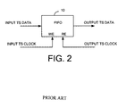
- the receiver writes the input transport stream in a FIFO (First-In First-Out) memory 10 in response to an input TS clock and reads out the written transport stream in response to an output TS clock in order to produce an output transport stream. Therefore, the FIFO memory 10 acts as a buffer.
- the input TS clock signal is generated by reference to the input transport stream. If a frequency of the input TS clock is the same as that of the output TS clock, a writing speed and a reading speed of the FIFO memory 10 are the same and no problems occur.
- a null packet generator 12 is provided to generate a null packet that is a dummy packet.
- Control means 14 watches the writing speed and the reading speed of the FIFO memory 10 and controls an electronic switch 16 to insert the null packet into the output transport stream from the FIFO memory when a difference between the writing and reading speeds exceeds an allowable range.
- Out of the allowable range means a situation that the volume of the input (transport) stream stored in the FIFO memory 10 is equal to or less than a predetermined value in accordance with the speed difference between the reading and writing speeds and this situation is just before a situation that it is hard to read out the stream from the FIFO memory in accordance with the speed difference.
- FIG. 3 An operation as illustrated in FIG. 3 will be discussed by reference to FIG. 1.
- each packet data volume of the input transport stream A is the same as that of the output transport stream B, and each packet length of the output transport stream B is shorter than that of the input transport stream A because the reading speed is higher than the writing speed.
- FIGs. 2 and 3 the same reference numbers have been employed to designated like blocks and their operations will not be explained, as they are known to those skilled in the art.
- an electronic switch 16 selects the FIFO memory 10.
- the input transport stream A shown in FIG. 1 is written in the FIFO memory 10 in response to the input TS clock.
- the packet A is read out as the output transport steam B of FIG. 1 in response to the output TS clock.
- the packet B is not written in the FIFO memory 10 completely after the packet A is read out. Then, the control means 14 detects this situation of the out of the allowable range, makes the electronic switch 16 select the null packet generator 12 so as to insert the null packet into the output transport stream B. Since the packet B of the input transport stream A is being written in the FIFO memory 10 at a time when the null packet is completely inserted, the control means 14 makes the electronic switch 16 to select the FIFO memory 10 so as to read out the packet B from the FIFO memory 10 as the output transport stream. The operation of writing the packet C of the input transport stream into the FIFO memory 10 is completed at a time when the packet B is completed to be read out. Ongoingly, the FIFO memory 10 is in the reading operation to produce the packet C as the output transport stream.
- the time information PCR representative of the time reference is set to the packet B.
- the null packet as the dummy is inserted between the packets A and B. Since the time information of the PCR in the packet B takes no account of the time for the dummy packet, a disadvantage is that a PCR jitter occurs.
- a first PCR detection means 18 detects a PCR value from the input transport stream.
- Comparator means 20 compares the PCR value detected by the PCR detection means 18 with the counted value of a PCR counter 24 so as to control an oscillation frequency (for example 27 MHz) of a voltage controlled oscillator (VCO) 22 in accordance with the difference of these values.
- the counter 24 counts a pulse signal from the VCO 22.
- the blocks 20, 22 and 24 operate such that the counted value of the counter 24 is in synchronism with the PCR of the input transport stream.
- a second PCR detection means 26 detects the PCR in the transport stream from the electronic switch 16.
- a PCR exchange means 28 exchanges the PCR value in the transport stream from the electronic switch 16 with the counted value of the counter 24 in response to a detection signal from the second PCR detection means 26 (that represents a detection timing of the PCR). Even if the null (dummy) packet is inserted between the packet A and the packet B as shown in FIG. 1, the PCR counter 24 counts a time for the null packet and thereby the PCR of the packet B is replaced with the new PCR value that takes account of the period of the null packet.
- Such apparatus is disclosed in, for example, Japanese Unexamined Patent Publication No. 11-239179 .
- the digital transmission apparatus in FIG. 4 if a transmission is interrupted, the PCR in the packet with PCR becomes an outlying value so that the oscillation frequency of the VCO gets out of order significantly, the counted value of the PCR counter 24 gets out of order too and the PCR exchange means 28 cannot exchange the PCR correctly.
- an offset between the counted value from the counter 24 and the PCR value detected by the PCR detection means 18 becomes unstable, so that the PCR value as well as PTS (Presentation Time Stamp) / DTS (Decoding Time Stamp) values should be corrected.
- PTS Presentation Time Stamp
- DTS Decoding Time Stamp
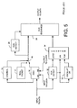
- a first PCR detection means 30 detects the PCR from the input transport stream, applies the PCR value to a load terminal of a counter 34 and applies a detection signal representative of the PCR detection timing to a preset terminal PR of the counter 34 and to a synchronous oscillator 32.
- the synchronous oscillator 32 oscillates a 27 MHz pulse signal in synchronism with the PCR detection timing.
- the counter 34 loads the PCR when the PCR detection means 30 detects the PCR in the input transport stream and then the counter 34 counts the output pulse from the oscillator 32 from this load value. Therefore, the counter 34 is reset to the PCR value every time when detecting the packet with the PCR from the input transport stream and then the counter 34 counts the pulse from the oscillator 32 from the value to reset to the PCR value.
- the PCR exchange means 28 exchanges the PCR value of the output transport stream with the PCR value generated by the counter 34 every time when the second PCR detection means 26 detects the PCR in the output from the switch 16. This apparatus is disclosed in, for example, Japanese Unexamined Patent Publication No. 2005-151153 .
- each program has its own PCR having a different continuity so that the first PCR detection means 30 should detect which program belongs to the detected PCR and a counter 34 is required for each program. Moreover, the PCR exchange means 28 should recognize which program belongs to the PCR detected by the second PCR detection means 26 and should select one of the plurality of counters for exchanging the PCR.
- the apparatus of FIG. 5 can improve the PCR jitter but is expensive in configuration. The above description is for MPEG-2 system but there is a similar problem in digital data transmission other than MPEG-2 system.
- Such apparatus and method is desired to be simple in configuration and inexpensive for multiple stream trains, e.g., transport streams for multiple programs.
- An aspect of the present invention is a digital transmission apparatus for storing an input stream in a memory at a writing speed, the input stream comprising a packet train including a packet to which time information representative of a time reference is set, and for reading out an output stream from said memory at a reading speed higher than the writing speed, the digital transmission apparatus, comprising: first detection means for generating a first detection signal when detecting the time information in the input stream; oscillation means for oscillating a local clock signal having a frequency of a reference clock for the input stream; a counter for counting the local clock signal from said oscillation means; first latch means for latching the counted value of said counter in response to the first detection signal; first exchange means for subtracting the counted value latched by said first latch means from the time information in the input stream and applying an input stream having the subtracted result as new time information to said memory; dummy insertion means for inserting a dummy packet into the output stream from said memory when a difference between the reading speed and the writing speed exceeds an allowable range;
- Another aspect of the present invention is a digital transmission method for storing an input stream in a memory at a writing speed, the input stream comprising a packet train including a packet to which time information representative of a time reference is set, and for reading out an output stream from said memory at a reading speed higher than the writing speed
- the digital transmission method comprising the steps of: obtaining a first latch value by latching a counted value of a counter when detecting the time information in the input stream, said counter counting a frequency signal of a reference signal for the input stream; subtracting the first latch value from the time information in the input stream and applying an input stream having the subtracted result as new time information to said memory; inserting a dummy packet into the output stream from said memory when a difference between the reading speed and the writing speed exceeds an allowable range; obtaining a second latch value by latching a counted value of said counter when detecting the time information in the output stream having the inserted dummy packet; and adding the second latch value to the time information in the output stream and
- Embodiments of the present invention improve the jitter of time information when writing an input stream in a memory and reading it therefrom, the input stream comprising a packet train including a packet to which time information representative of a time reference is set.
- Some embodiments of this invention are simple and inexpensive for handling multiple stream trains.
- FIG. 1 is a drawing for explaining a transport stream.
- FIG. 2 is a block diagram for explaining a prior art.
- FIG. 3 is a block diagram for explaining another prior art that improves FIG. 2.
- FIG. 4 is a block diagram for explaining another prior art that improves FIG. 3.
- FIG. 5 is a block diagram for explaining another prior art that improves FIG. 4.
- FIG. 6 is a block diagram of an embodiment according to the present invention.
- FIG. 6 shows a block diagram of an embodiment according to the present invention, where the invention is applied to MPEG-2 system.
- the same reference numbers in FIG. 6 have been employed to designate like blocks in FIGs. 2-5.
- a first PCR exchange circuit 36 detects the time information PCR representative of the time reference and exchanges it.
- This PCR exchange circuit 36 comprises a PCR detection section (first detection means) 38 and a PCR exchange section (first exchange means) 40.
- the PCR detection section 38 generates a first detection signal when detecting the PCR set to a packet header of the input transport stream.
- the first detection signal is applied as a latch timing signal to a latch circuit (first latch means) 42 and as a sync signal to a synchronous oscillator (oscillation means) 44.
- the oscillator 44 comprises, for example, the comparison means 20 and the VCO 22 of FIG. 4 and a feedback path for feeding the output signal from the VCO back to the comparison means.
- the oscillator 44 oscillates a local clock signal, e.g., 27 MHz clock signal, in synchronism with the detection signal from the PCR detection section 38.
- a counter 46 is, for example, a 42-bit counter, and counts the local clock signal from the oscillator 44 to apply the counted value (digital data) to the latch circuit 42 and another latch circuit (second latch means) 48.
- the latch circuit 42 latches the counted value (C0) of the counter 46 at a time when receiving the first detection signal from the PCR detection section 38 or detecting the PCR in the input transport stream.
- the memory 10 is a FIFO memory to which the transport stream from the PCR exchange section 40, in response to an input TS clock, and from which the stream is read out, in response to an output TS clock. Since the output TS clock frequency is higher than the input TS clock frequency, the reading speed is faster than the writing speed.
- the control means 14 monitors an operation condition of the FIFO memory 10. When a difference between the writing speed and the reading speed exceeds an allowable range or is the out of the allowable range, the control means 14 makes the electric switch 16 to select the null (dummy) packet generator 12 instead of the FIFO memory 10.
- the null packet is inserted into the transport stream B from the memory 10 as shown in FIG. 1.
- the control means 14 makes the electronic switch 16 to select the FIFO memory 10.
- These null packet generator 12, control means 14 and electronic switch 16 act as the dummy insertion means.
- a fact that the difference between the writing and reading speeds is out of the allowable range means that the volume of the input transport stream stored in the FIFO memory 10 is equal to or less than a predetermined value in accordance with the speed difference between the reading and writing speeds and this situation happens before a situation that it is hard to read out the stream from the FIFO memory 10 in accordance with the speed difference.
- the output terminal of the electronic switch 16 is connected to a second PCR exchange circuit 50.
- This second PCR exchange circuit 50 comprises a PCR detection section (second detection means) 52 and a PCR exchange section (second exchange means) 54.
- the PCR detection section 52 generates a second detection signal when detecting the PCR in the output transport stream from the electronic switch 16.
- the counter 46 is a ring (circulating) counter that counts continuously the local clock signal from the oscillator 44.
- the latch circuit 48 latches the counted value C1 of the counter 46 in response to the second detection signal from the PCR detection section 52.
- the PCR exchange section 54 adds the counted value C1 latched by the latch circuit 48 to the PCR value P2 in the output transport stream in response to the detection signal from the PCR detection section 52 so as to produce a new PCR value.
- the final output is the transport stream having the exchanged PCR.
- P2 P1.
- the value C1-C0 corresponds to a propagation delay time while the transport stream transmits from the first PCR exchange circuit 36 (PCR detection section 38) to the second PCR exchange circuit 50 (PCR exchange section 54). If this propagation delay time can be ignored, the value C1-C0 is substantially zero and the PCR in the output transport stream is the same as the PCR in the input transport stream.
- the value C1-C0 is a sum of the insertion period of the null packet and the propagation delay time from the first PCR exchange circuit 36 to the second PCR exchange circuit 50. If the propagation delay time can be ignored, the value C1-C0 corresponds to the insertion period of the null packet. Then, the PCR of the output transport stream is a sum of the PCR in the input transport stream and the period of the inserted null packet. Therefore, the continuity of the PCR can be kept and the PCR jitter can be improved when the null packet is inserted. If the null packet is not inserted prior to the packet with PCR, the above situation can be applied.
- the propagation delay time is a fixed value.
- the compensation value H may be obtained with an actual measurement by applying a transport stream having a dummy PCR as an input transport stream.
- the PCR value in the transport stream flowing through the digital transmission apparatus of the present invention is always based on the original PCR regardless of the exchange. Moreover, the original PCR is not replaced with a completely different PCR when compensating the dummy packet. Therefore, in a case that plural programs are combined to a single stream where the PCR continuities of the programs are different from each other, the present invention does not need a dedicated circuit for each program and can use the first and second PCR exchange circuits, the latch circuits, the counter, etc. in common for all the programs.
- the oscillator 44 operates in synchronization with the PCR in the input transport stream.
- the oscillator 44 of 27 MHz oscillation frequency may be an asynchronous oscillator having 50 ppm accuracy. In this case, it is not necessary to apply the detection signal from the first PCR detection section 38 to the oscillator 44.
- the present invention can be applied to a system other than the MPEG-2 system where the input stream written in the memory comprises a packet train including a packet to which time information representative of a time reference is set.
- the electronic switch 16 may be a digital multiplexer.
Landscapes
- Engineering & Computer Science (AREA)
- Multimedia (AREA)
- Signal Processing (AREA)
- Compression Or Coding Systems Of Tv Signals (AREA)
- Time-Division Multiplex Systems (AREA)
- Data Exchanges In Wide-Area Networks (AREA)
- Use Of Switch Circuits For Exchanges And Methods Of Control Of Multiplex Exchanges (AREA)
- Synchronisation In Digital Transmission Systems (AREA)
Applications Claiming Priority (1)
| Application Number | Priority Date | Filing Date | Title |
|---|---|---|---|
| JP2006202749A JP2008034905A (ja) | 2006-07-26 | 2006-07-26 | デジタル伝送装置及び方法 |
Publications (2)
| Publication Number | Publication Date |
|---|---|
| EP1883247A2 true EP1883247A2 (de) | 2008-01-30 |
| EP1883247A3 EP1883247A3 (de) | 2010-05-26 |
Family
ID=38657716
Family Applications (1)
| Application Number | Title | Priority Date | Filing Date |
|---|---|---|---|
| EP20070252963 Withdrawn EP1883247A3 (de) | 2006-07-26 | 2007-07-26 | Vorrichtung und Verfahren zur digitalen Übertragung |
Country Status (3)
| Country | Link |
|---|---|
| US (1) | US7817765B2 (de) |
| EP (1) | EP1883247A3 (de) |
| JP (1) | JP2008034905A (de) |
Cited By (2)
| Publication number | Priority date | Publication date | Assignee | Title |
|---|---|---|---|---|
| GB2444408A (en) * | 2006-11-14 | 2008-06-04 | Toshiba Kk | Adjusting transport stream data rate based on comparison of timestamps inserted in packets with a locally-generated reference |
| WO2010005416A1 (en) * | 2008-07-09 | 2010-01-14 | Tandberg Television Inc. | Constant bit rate padding of mpeg transport streams |
Families Citing this family (5)
| Publication number | Priority date | Publication date | Assignee | Title |
|---|---|---|---|---|
| US7899089B2 (en) * | 2008-07-09 | 2011-03-01 | Ericsson Television, Inc. | Constant bit rate padding of MPEG transport streams |
| JP5820567B2 (ja) * | 2010-03-04 | 2015-11-24 | スパンション エルエルシー | 解析システム及び半導体装置 |
| JP2012222604A (ja) * | 2011-04-08 | 2012-11-12 | Sony Corp | データ読み出し装置、データ読み出し方法、並びにプログラム |
| US8514329B2 (en) | 2011-05-31 | 2013-08-20 | Motorola Mobility Llc | Jitter estimation for MPEG receivers |
| US9703526B2 (en) * | 2015-03-12 | 2017-07-11 | Altera Corporation | Self-stuffing multi-clock FIFO requiring no synchronizers |
Family Cites Families (5)
| Publication number | Priority date | Publication date | Assignee | Title |
|---|---|---|---|---|
| US5742623A (en) * | 1995-08-04 | 1998-04-21 | General Instrument Corporation Of Delaware | Error detection and recovery for high rate isochronous data in MPEG-2 data streams |
| US6940873B2 (en) * | 2000-12-27 | 2005-09-06 | Keen Personal Technologies, Inc. | Data stream control system for associating counter values with stored selected data packets from an incoming data transport stream to preserve interpacket time interval information |
| JP2003101976A (ja) | 2001-09-26 | 2003-04-04 | Toshiba Corp | ストリーム生成装置 |
| JP2005151153A (ja) | 2003-11-14 | 2005-06-09 | Hitachi Kokusai Electric Inc | デジタル伝送システム |
| US7561582B2 (en) * | 2004-01-07 | 2009-07-14 | Panasonic Corporation | Data reception device |
-
2006
- 2006-07-26 JP JP2006202749A patent/JP2008034905A/ja not_active Abandoned
-
2007
- 2007-07-25 US US11/828,271 patent/US7817765B2/en not_active Expired - Fee Related
- 2007-07-26 EP EP20070252963 patent/EP1883247A3/de not_active Withdrawn
Non-Patent Citations (3)
| Title |
|---|
| "Systems FAQ" JOINT VIDEO TEAM (JVT) OF ISO/IEC MPEG & ITU-T VCEG(ISO/IEC JTC1/SC29/WG11 AND ITU-T SG16 Q6), XX, XX, no. N2223, 20 March 1998 (1998-03-20), XP030010706 * |
| LIANG LONGFEI ET AL: "Implementation of a New MPEG-2 Transport Stream Processor for Digital Television Broadcasting" IEEE TRANSACTIONS ON BROADCASTING, IEEE SERVICE CENTER, PISCATAWAY, NJ, US LNKD- DOI:10.1109/TBC.2002.806799, vol. 48, no. 4, 1 December 2002 (2002-12-01), XP011070282 ISSN: 0018-9316 * |
| XINGDONG W ET AL: "IMPLEMENTATION OF MPEG-2 TRANSPORT STREAM REMULTIPLEXER FOR DTV BROADCASTING" IEEE TRANSACTIONS ON CONSUMER ELECTRONICS, IEEE SERVICE CENTER, NEW YORK, NY, US LNKD- DOI:10.1109/TCE.2002.1010139, vol. 48, no. 2, 1 May 2002 (2002-05-01), pages 329-334, XP001200461 ISSN: 0098-3063 * |
Cited By (4)
| Publication number | Priority date | Publication date | Assignee | Title |
|---|---|---|---|---|
| GB2444408A (en) * | 2006-11-14 | 2008-06-04 | Toshiba Kk | Adjusting transport stream data rate based on comparison of timestamps inserted in packets with a locally-generated reference |
| GB2444408B (en) * | 2006-11-14 | 2009-02-11 | Toshiba Kk | Broadcast transport stream distribution system,and broadcast transport stream distribution apparatus, user terminal device and distribution method |
| US8832291B2 (en) | 2006-11-14 | 2014-09-09 | Kabushiki Kaisha Toshiba | Broadcast transport stream distribution system, and broadcast transport stream distribution apparatus, user terminal device and distribution method for use in the system |
| WO2010005416A1 (en) * | 2008-07-09 | 2010-01-14 | Tandberg Television Inc. | Constant bit rate padding of mpeg transport streams |
Also Published As
| Publication number | Publication date |
|---|---|
| JP2008034905A (ja) | 2008-02-14 |
| US7817765B2 (en) | 2010-10-19 |
| US20080152064A1 (en) | 2008-06-26 |
| EP1883247A3 (de) | 2010-05-26 |
Similar Documents
| Publication | Publication Date | Title |
|---|---|---|
| US7817765B2 (en) | Digital transmission apparatus and methods | |
| US6493832B1 (en) | Communication apparatus which handles a time stamp | |
| JP4528010B2 (ja) | ビデオ同期 | |
| US7436456B2 (en) | Video device and method for synchronising time bases of video devices | |
| CN101175215B (zh) | 时序恢复方法及其系统 | |
| US20080055485A1 (en) | Generation of a Frame Synchronized Clock for a Wireless Video Receiver | |
| JP5068758B2 (ja) | データ再生回路 | |
| US20060020843A1 (en) | Technique to create link determinism | |
| TWI455573B (zh) | 恢復系統時鐘的裝置和方法 | |
| US20120177160A1 (en) | Communication circuit and method of adjusting sampling clock signal | |
| KR100915771B1 (ko) | Pcr 보정 회로 | |
| US20100074254A1 (en) | Communication system, transmitting apparatus, receiving apparatus, communication method, and record medium | |
| US7301971B2 (en) | Method and apparatus for continuous synchronization of a plurality of asynchronous data sources | |
| EP0873019A2 (de) | Vorrichtung und Verfahren zum Ubertragen von digitalen Audio- und Videodaten | |
| US8477789B2 (en) | Transmission device and reception device | |
| US20040218633A1 (en) | Method for multiplexing, in MPEG stream processor, packets of several input MPEG streams into one output transport stream with simultaneous correction of time stamps | |
| JP2001203662A (ja) | Sdh試験装置 | |
| US6806818B2 (en) | Apparatus and method for digital stream conversion | |
| JP4425115B2 (ja) | クロック同期装置およびプログラム | |
| US7869467B2 (en) | Receiving device including packet output circuit for outputting control signal | |
| US20230021109A1 (en) | Dp-out adapter and associated control method | |
| JP2010098519A (ja) | クロック再生システムおよび方法 | |
| KR100817248B1 (ko) | Ieee 1394 버스로 전송되는 mpeg 기록된 데이터를판독하는 방법 및 장치 | |
| JP4613080B2 (ja) | クロック再生情報生成回路及びクロック再生回路 | |
| US20090232266A1 (en) | Signal processing device |
Legal Events
| Date | Code | Title | Description |
|---|---|---|---|
| PUAI | Public reference made under article 153(3) epc to a published international application that has entered the european phase |
Free format text: ORIGINAL CODE: 0009012 |
|
| AK | Designated contracting states |
Kind code of ref document: A2 Designated state(s): AT BE BG CH CY CZ DE DK EE ES FI FR GB GR HU IE IS IT LI LT LU LV MC MT NL PL PT RO SE SI SK TR |
|
| AX | Request for extension of the european patent |
Extension state: AL BA HR MK YU |
|
| 17P | Request for examination filed |
Effective date: 20080714 |
|
| PUAL | Search report despatched |
Free format text: ORIGINAL CODE: 0009013 |
|
| AK | Designated contracting states |
Kind code of ref document: A3 Designated state(s): AT BE BG CH CY CZ DE DK EE ES FI FR GB GR HU IE IS IT LI LT LU LV MC MT NL PL PT RO SE SI SK TR |
|
| AX | Request for extension of the european patent |
Extension state: AL BA HR MK RS |
|
| AKX | Designation fees paid |
Designated state(s): DE FR GB IT |
|
| STAA | Information on the status of an ep patent application or granted ep patent |
Free format text: STATUS: THE APPLICATION IS DEEMED TO BE WITHDRAWN |
|
| 18D | Application deemed to be withdrawn |
Effective date: 20101127 |