EP1884286B1 - Luftverschiebungspipette - Google Patents
Luftverschiebungspipette Download PDFInfo
- Publication number
- EP1884286B1 EP1884286B1 EP07019160.6A EP07019160A EP1884286B1 EP 1884286 B1 EP1884286 B1 EP 1884286B1 EP 07019160 A EP07019160 A EP 07019160A EP 1884286 B1 EP1884286 B1 EP 1884286B1
- Authority
- EP
- European Patent Office
- Prior art keywords
- tip
- pipette
- shaft
- mounting shaft
- region
- Prior art date
- Legal status (The legal status is an assumption and is not a legal conclusion. Google has not performed a legal analysis and makes no representation as to the accuracy of the status listed.)
- Expired - Lifetime
Links
- 238000006073 displacement reaction Methods 0.000 title claims description 13
- 238000007789 sealing Methods 0.000 claims description 102
- 230000035515 penetration Effects 0.000 claims description 11
- 208000012514 Cumulative Trauma disease Diseases 0.000 claims description 4
- 238000003780 insertion Methods 0.000 description 30
- 230000037431 insertion Effects 0.000 description 30
- 239000012530 fluid Substances 0.000 description 21
- 230000007246 mechanism Effects 0.000 description 19
- 238000013461 design Methods 0.000 description 13
- 210000003813 thumb Anatomy 0.000 description 9
- 230000013011 mating Effects 0.000 description 7
- 239000007788 liquid Substances 0.000 description 5
- 206010038584 Repetitive strain injury Diseases 0.000 description 4
- 239000000463 material Substances 0.000 description 4
- 239000011324 bead Substances 0.000 description 3
- 239000011435 rock Substances 0.000 description 3
- 208000003295 carpal tunnel syndrome Diseases 0.000 description 2
- 230000000694 effects Effects 0.000 description 2
- 230000006872 improvement Effects 0.000 description 2
- 230000009467 reduction Effects 0.000 description 2
- 230000000087 stabilizing effect Effects 0.000 description 2
- 238000012546 transfer Methods 0.000 description 2
- 230000009471 action Effects 0.000 description 1
- 238000013459 approach Methods 0.000 description 1
- 238000003556 assay Methods 0.000 description 1
- 230000004323 axial length Effects 0.000 description 1
- 238000011109 contamination Methods 0.000 description 1
- 230000000994 depressogenic effect Effects 0.000 description 1
- 210000003811 finger Anatomy 0.000 description 1
- 210000000245 forearm Anatomy 0.000 description 1
- 238000009434 installation Methods 0.000 description 1
- 230000014759 maintenance of location Effects 0.000 description 1
- 238000004519 manufacturing process Methods 0.000 description 1
- 238000000034 method Methods 0.000 description 1
- 238000012986 modification Methods 0.000 description 1
- 230000004048 modification Effects 0.000 description 1
- 239000002245 particle Substances 0.000 description 1
- 238000003825 pressing Methods 0.000 description 1
- 230000004044 response Effects 0.000 description 1
- 238000012360 testing method Methods 0.000 description 1
- 230000007704 transition Effects 0.000 description 1
- 238000013519 translation Methods 0.000 description 1
Images


Classifications
-
- B—PERFORMING OPERATIONS; TRANSPORTING
- B01—PHYSICAL OR CHEMICAL PROCESSES OR APPARATUS IN GENERAL
- B01L—CHEMICAL OR PHYSICAL LABORATORY APPARATUS FOR GENERAL USE
- B01L3/00—Containers or dishes for laboratory use, e.g. laboratory glassware; Droppers
- B01L3/02—Burettes; Pipettes
-
- B—PERFORMING OPERATIONS; TRANSPORTING
- B01—PHYSICAL OR CHEMICAL PROCESSES OR APPARATUS IN GENERAL
- B01L—CHEMICAL OR PHYSICAL LABORATORY APPARATUS FOR GENERAL USE
- B01L3/00—Containers or dishes for laboratory use, e.g. laboratory glassware; Droppers
- B01L3/02—Burettes; Pipettes
- B01L3/0275—Interchangeable or disposable dispensing tips
Definitions
- the present invention relates to an air displacement pipette in accordance with preamble of claim 1.
- An air displacement pipette of this kind is known from US-A-4,824,641 which relates to an air displacement pipette incorporated into an automated sample handling device and to pipette tips therefor.
- the present invention relates to improvements in air displacement pipettes including a novel mounting shaft and a unique pipette tip tailored to the mounting shaft such that the tip is easily insertable by a pipette user onto the shaft to a fluid tight position in which the tip is secured against undesired lateral rocking on or displacement from the shaft and, after use, is easily ejectable from the shaft by the pipette user; such tip insertion and ejection requiring the pipette user to only exert axial tip insertion and ejection forces of about 4.45 Newton (one pound) or less thereby substantially eliminating all risk of repetitive motion injury to the pipette user.
- pipette devices for the transfer and dispensing of precise quantities of fluids in analytical systems is well known as is the use of disposable tip members for such pipettes. Disposable tips accommodate the serial use of such pipette devices in the transfer of different fluids without carryover or contamination.
- disposable pipette tips are formed of a plastic material and are of a hollow, elongated, generally conical shape with an open proximal end for receiving and releasably mating with the distal end of an elongated generally conical pipette tip mounting shaft of a pipette device.
- the disposable tip should slide easily onto the mounting shaft to an axial position adjacent a lower end of a tip ejection mechanism of the pipette device.
- the pipette tip should be laterally stable on the shaft, free from external rocking relative to the shaft (as during "touching off"), and should form a fluid tight annular seal with the mounting shaft. Then when it is desired to replace the tip with a new tip, the pipette tip should be easily removed from the mounting shaft by operation of the tip ejection mechanism.
- the inner surface and side walls of the proximal portions of most pipette tips are axially tapered at a one to one and a half degree greater angle than the distal end of the pipette tip mounting shaft and form an axially elongated frusto-conical annular sealing band.
- the sealing band is dimensioned to stretch outwardly ("hoop stretch") as the distal end of the elongated generally conical pipette tip mounting shaft is forced into the proximal end of the tip to firmly seat the tip on the shaft and to create an axially elongated annular fluid tight seal between the sealing band and the mounting shaft.
- pipette tips such as those described in United States patents 4,748,859 and 4,824,641 , include a plurality of axially spaced compressible annular sealing rings on an inner surface of the proximal end portion of such tips.
- the rings create multiple axially spaced fluid tight annular seals between the outer surface of the pipette tip mounting shaft and the inner surface of the proximal end portion of the tip which by virtue of the axially spaced rings is laterally stabilized against undesired rocking on the shaft during touching off.
- US-A-5,232,689 describes a pipette tip for an automated assay testing system with annular sealing beads on the inside of the proximal portion of the tip.
- the upper sealing band is disposed axially spaced from the open proximal end of the tip and the tip has axial ribs at the proximal end which stiffden it locally. Both these features are counterproductive when low ejection forces are desired.
- US-A-4,961350 also describes a pipette tip with a relatively thick wall portion at the proximal end which is stiffened by exrternal ribs so that the end portion has a high stability.
- the design criteria for disposable pipette tips that they be stably mountable on and form a fluid tight seal with a pipette mounting shaft is more easily achieved than the design criteria that disposable pipette tips slide easily onto a pipette tip mounting shaft to an axial location forming a fluid tight seal and then be easily removable from the mounting shaft when it is desired to replace the tip.
- the pipette tip mounting shafts of devices for pipetting volumes of liquid in different ranges have different external shape.
- the distal end of standard pipette tip mounting shafts of pipettes for pipetting liquids in volumes greater than 500 microliters (large volume pipettes) commonly have a downward and inward axial taper of about one and one half to two and one half degrees per side from the longitudinal axis of the mounting shaft.
- the distal end of the mounting shafts of moderate to relatively small volume pipette devices commonly have a downward and inward axial taper of about two to five degrees per side from the longitudinal axis of the mounting shaft so that the nose of the shaft will hit the inner wall of the pipette tip and cause hoop stretching thereof before the side of the shaft engages the inner wall of the tip.
- standard small and moderate volume pipette tips include a frusto-conical annular sealing band or inner surface for engaging and sealing with the tapered distal end of a pipette tip mounting shaft.
- the angle of taper of the sealing surface usually approximates (e.g. one and one-half degrees greater than) that of the mounting shaft (e.g. two to five degrees). Thinning the side wall of the standard small and moderate volume pipette tips in the region of such a sealing band does little to reduce the mounting and ejection forces required to move such a tip to a sealing location and then eject the pipette tip from the mounting shaft.
- the frusto-conical annular region is required to stretch like a hoop (hoop stretch) outwardly normal to the mating sloping surface of the pipette tip mounting shaft.
- Large reactive forces in the tip material resist such hoop stretching and require the exertion of large axial forces (e.g. 45 Newton or more (ten or more pounds)) on the tip in order to mount the tip on the mounting shaft and create the necessary annular fluid tight seal.
- large axial forces e.g. 45 Newton or more (ten or more pounds)
- disposable pipette tips are commonly mounted and stored in sterilizable racks.
- racks commonly include a support tray having an array of holes for receiving distal ends of pipette tips to vertically orient the pipette tips in a spaced rectilinear pattern with open proximal ends of the tips exposed to receive the mounting shafts of a pipette device onto which the pipette tips are to be mounted.
- the pipette device is placed over the rack with its several mounting shafts aligned with the open proximal ends of an aligned series of the pipette tips.
- some manufacturers include O-rings on and encircling the tip mounting shafts of their pipettes.
- the Brinkmann Instrument Co. indicates for its Transferpipette 8/12 that such O-rings ensure that all tips stay firmly mounted during use.
- there is a rapid wearing of such O-rings with repeated insertion of the associated mounting shafts into and ejection of pipette tips from such shafts. With such wear, the tips no longer stay firmly mounted during use and wear particles from the O-rings can contaminate fluid samples handled by the associated pipettes.
- the improved pipette tip hereinafter referred to as the "Soft Seal” tip, includes an open tubular proximal end portion comprising an enlarged frusto-conical open top tapering downwardly and inwardly to join at an annular sealing region to a hollow substantially cylindrical mid-portion of the pipette tip.
- the open top has an inner diameter sufficient to axially receive the distal end of a standard pipette tip mounting shaft.
- the annular sealing region is formed by the transition or line of connection of the frusto-conical open top to the mid-portion of the pipette and includes an annular sidewall having a thickness in a range of .20 to .50 mm.
- the mid-portion has an inner diameter at the sealing region which is less than the diameter of the pipette mounting shaft, a thin resilient annular side wall having a thickness in a range of .20 to .50 mm and an axial length in a range of .25 to .65 cm.
- the frusto-conical outer surface of the mounting shaft engages the inner surface of the sealing region at the bottom of the open top of the pipette tip to stretch the annular sealing region or line radially outward as the mounting shaft is inserted into the proximal portion, thereby creating a fluid tight seal between the sealing zone and the sealing region.
- the improved pipette tip includes a tubular distal portion extending from the mid-portion and terminating in a relatively narrow distal end opening for passing fluid into and from the tip upon operation of the pipette device.
- the improved pipette tip preferably includes lateral stabilizing means on its inner surface adjacent the sealing region for engaging the outer surface of the mounting shaft as it is inserted into the proximal portion to laterally stabilize the tip on the shaft.
- lateral stabilizing means preferably comprises at least three circumferentially spaced contacts extending inwardly from the inner surface of the proximal portion of the tip adjacent the sealing region for engaging the outer surface of the mounting shaft as it is inserted into the proximal portion to laterally stabilize the tip on the shaft.
- the diametric spacing of the contacts is such that the contacts lightly engage and allow the distal end of the shaft to pass with no hoop stretching of the sidewalls from which the contacts extend.
- the contacts combine with the sealing region to provide lateral support for the pipette tip on the mounting shaft and prevent the pipette tip from moving laterally when lateral external forces are exerted on the distal portion of the tip as during touching off.
- an air displacement pipette comprising a pipette tip mounting shaft and a disposable pipette tip having a proximal end mountable onto the tip mounting shaft and a distal sample receiving end, the shaft having substantially cylindrical and axially spaced outer surface zones including an annular sealing zone and a lateral support zone, and the tip having corresponding axially spaced inner regions including an annular sealing region and a lateral support region, a sidewall in the annular sealing region of the tip being made annular and sufficiently thin that the sealing region expands slightly to form an interference fit and air tight seal between a sealing surface on an inner surface of the sidewall and the sealing zone of the shaft when the tip is mounted on the shaft and the sealing zone penetrates the sealing region, the tip characterized by:
- EP-A-0148333 which also relates to a disposable pipette tip formed for automatic installation.
- the reference refers, in the first full sentence on page 3, to the total friction between the tip and the barrel caused by a conical form of the tip (page 2, lines 20 to 23) to the total friction between the barrel and the tip being unimportant because such pipettes and tips are primarily for hand control or operation, either singly or as a group.
- the present teaching relates to the concept of axially spaced annular sealing and substantially cylindrical lateral support zones and regions on the pipette's mounting shaft and tip, respectively. Further, it provides means for insuring uniform depth of mounting shaft penetration into the pipette tip to maintain uniform tip interference with the mounting shaft as successive tips are mounted on and ejected from the mounting shaft.
- the present teaching relates to a combination of a pipette tip mounting shaft and pipette tip in an air displacement pipette.
- the mounting shaft comprises an axially elongated body including a distal end and annular or substantially cylindrical and axially spaced outer surface regions defining an annular sealing zone and an annular lateral support zone.
- the pipette tip is an elongated tube comprising an open proximal end, an open conical distal end and annular or substantially cylindrical and axially spaced inner surface regions defining an annular sealing region and an annular lateral support region.
- the outer diameter of the annular sealing zone on the mounting shaft is slightly greater than the inner diameter of the annular sealing region on the pipette tip and the sidewall of the tip in the area of the annular sealing region is sufficiently thin that the annular sealing region expands slightly to form an interference fit and air tight seal between the mounting shaft and the pipette tip when the sealing zone penetrates the sealing region.
- the axial spacing of the sealing and support zones is substantially equal to the axial spacing of the sealing and support regions.
- the outer diameter of the lateral support zone is substantially equal to the inner diameter of the lateral support region over at least some portion of the circumference of the support zone.
- the support region receives the support zone and provides lateral support therefor which prevents transverse rocking of the pipette tip on the mounting shaft as might otherwise occur during touching off of the pipette tip and an accompanying undesired dislodging of the tip from the shaft.
- the preferred embodiment of the present invention includes the aforementioned controlled interference air tight fit and mating annular lateral support zone and region as well as cooperative means on the pipette and pipette tip for limiting the axial travel of the tip on the mounting shaft. This insures uniform depth of mounting shaft penetration into the pipette tip to maintain uniform the desired tip interference with the mounting shaft as successive tips are mounted on and ejected from the mounting shaft and is to be distinguished from the pipette tip shoulder structure of previously mentioned US-A-4,824,641 .
- the pipette tip combination of the present invention has proven to only require axial pipette tip mounting and ejection forces substantially equal to or less than 4.45 Newton (one pound) and to provide a stable air-tight seal of the tip on the shaft which is secure against undesired lateral rocking of the pipette tip on the mounting shaft.
- the combination comprising the present invention requires a pipette user to generate so little hand and thumb force that repeated mounting and ejection of such pipette tips is unlikely to result in repetitive stress injury.
- FIG. 1 this drawing illustrates a standard manual pipette resembling the PIPETMAN pipette sold exclusively in the United States by the Rainin Instrument Co. Inc., assignee of the present invention.
- the manual pipette is designated in Fig. 1 by the number 10 and includes a pipette tip ejector mechanism 12 described in United States patent 3,991,617 issued November 16, 1976 , which is incorporated herein by this reference.
- the pipette 10 comprises a push button 14 connected by a rod 16 to a piston (not shown) located in the body or housing 18 of the pipette.
- the push button 14 may be depressed by a user exerting a downward force on the push button to cause downward movement of the piston of the pipette.
- a quantity of liquid to be sampled is sucked into a disposable pipette tip 20 releasably secured to a lower end of a pipette tip mounting shaft 22 of the pipette.
- the sample then may be transferred into another vessel by once more exerting a downward force on the push button 14.
- the pipette tip ejector mechanism 12 is employed to eject the tip 20 from the mounting shaft 22.
- the mechanism 12 comprises a push button 24 connected to a rod located in a passage (not shown) provided in an upper part of the hand holdable housing 18 of the pipette 10.
- the passage and rod are arranged so as to be able to impart to the rod a movement of translation parallel to an axis of the pipette in opposition to a spring (not shown) normally urging the rod in an upward position.
- a removable tip ejector member or arm 26 including a tubular upper end extends from a lower end of the rod and from the rod follows the general exterior contour of the housing 18 of the pipette to terminate in a sleeve 28.
- the sleeve 28 encircles a conical lower end 30 of the pipette tip mounting shaft 22 which tightly receives the upper end of the disposable pipette tip 20.
- a user grips the pipette housing 18 and using his or her thumb presses downward on the push button 24.
- the downward force on the push button is translated by the rod to the tip ejector arm 26 and hence to the sleeve 28 which presses down on an upper end of the pipette tip.
- the pipette tip is propelled from the mounting shaft.
- the spring Upon a release of the push button 24, the spring returns the tip ejector mechanism 12 to its normal position with the sleeve spaced slightly from the upper end of a replacement pipette tip which is inserted onto the mounting shaft 22 readying the pipette 10 for its next aspiration and dispensing operation.
- the pipette tip mounting shaft 22 has an inward axial taper of between two and five degrees from the longitudinal axis of the mounting shaft.
- standard small and moderate volume pipettes tips for use with such standard pipette tip mounting shafts include a relatively long frusto-conical annular sealing band or inner surface contiguous with the open proximal end of the tip for engaging and sealing with the frusto-conical distal end of the pipette tip mounting shaft to provide lateral stability for the tip on the shaft.
- the angle of taper of the sealing surface is usually within about one degree of the two to five degrees inward taper of the mounting shaft and the length of the sealing surface on the shaft is such that in forming the annular seal the tip is also fairly stable on the shaft.
- the frusto conical annular sealing region along with the balance of the open proximal end of the pipette tip is required to stretch like a hoop outwardly normal to the mating sloping surface of the pipette tip mounting shaft.
- tip insertion and tip ejection forces The relationship between tip insertion and tip ejection forces is depicted by the curve 60 in Fig. 8 for a standard 250 ml pipette tip, the tip insertion forces increasing from 0 to 89.0 Newton (0 to about 20 pounds) at a point 62 where the tip engages an ejection mechanism of the associated pipette device.
- the downward tip ejection forces are exerted by the pipette user pressing downward with his or her thumb on the top of the push button 24 to translate axial force through the ejector arm 26 to the top of the pipette tip 20.
- Fig. 8 The relationship between tip insertion and tip ejection forces is depicted by the curve 60 in Fig. 8 for a standard 250 ml pipette tip, the tip insertion forces increasing from 0 to 89.0 Newton (0 to about 20 pounds) at a point 62 where the tip engages an ejection mechanism of the associated pipette device.
- the downward tip ejection forces
- the Soft Seal pipette tip design allows for the easy and firm mounting of a pipette tip on a mounting shaft and the easy ejection of the pipette tip from the mounting shaft by the application of axial mounting of about 26.7 Newton (6 pounds) and axial ejection forces of about 13.36 Newton (3 pounds).
- the point 72 depicts the applied force necessary to insert and eject the Soft Seal tip to and from a location on a standard pipette mounting shaft where the tip engages the tip ejection mechanism of an associated pipette.
- the substantial reduction in tip insertion and ejection forces associated with the Soft Seal pipette tip when compared to those of a standard pipette tip is clear from a comparison of curve 70 to curve 60.
- the present invention provides a novel mounting shaft and unique pipette tip tailored to the mounting shaft such that the tip is even more easily insertable by a pipette user onto the shaft to a fluid tight position in which the tip is secured against undesired lateral rocking on or displacement from the shaft and, which after use, is even more easily ejectable from the shaft by the pipette user.
- Such tip insertion and ejection operations require the pipette user to only exert axial tip insertion and ejection forces of about 4.45 Newton (one pound) or less, thereby substantially reducing all risk of repetitive motion injury to the pipette user.
- the design of the present invention referred hereinafter as the "LTS" tip and/or shaft, allows for the easy and firm mounting of the pipette tip of the present invention on its associated mounting shaft and the easy ejection of the pipette tip from the mounting shaft by the application of axial mounting and ejection forces of about 4.45 Newton (1 pound).
- the point 82 depicts the applied force necessary to insert and eject the LTS tip to and from a location on the mounting shaft of the present invention where the tip engages a tip insertion shoulder for limiting penetration of the shaft into the tip.
- such a shoulder comprises a shoulder on the tip or on the shaft or the base of a tip ejection mechanism of the associated pipette.
- Fig. 9 the relationship between the pipette tip insertion force and the distance traveled by a tip on an associated pipette tip mounting shaft is graphically depicted for 250 ml LTS, Soft Seal and standard pipette tips.
- the curves 100 and 110 depict the relationship between insertion force and the travel of the Soft Seal and standard pipette tips on standard mounting shafts respectively.
- the travel of Soft Seal and standard pipette tips is limited by the pipette tip ejection mechanism engaging the pipette tip as depicted by points 102 and 112 respectively.
- the curve 90 depicts the relationship between insertion force and LTS pipette tip travel on an LTS mounting shaft.
- the travel of the LTS pipette tip is limited by the previously referred to shoulder engaging the LTS tip as depicted by point 92 on curve 90.
- the substantial increase in tip travel per unit of insertion force associated with the LTS pipette tip of the present invention when compared to the Soft Seal and the standard pipette tip is clear from a comparison of curves 90, 100 and 110 in Fig. 9 .
- Fig. 10 the relation between the pipette tip insertion force and the lateral stability of a pipette tip on its associated shaft is graphically depicted for 250 microliter LTS, Soft Seal, and standard pipette tips.
- the axial location of the pipette tip on the standard pipette tip mounting shaft is the point where the pipette forms an air tight seal with the mounting shaft and is near or against the bottom of the pipette tip ejection mechanism for the associated pipette.
- the axial location of the tip is defined by the previously referred to shoulder.
- Each pipette tip was tested for stability by "touching off” the pipette tip during normal pipette use. That is, upon aspirating a volume of liquid into the distal of the pipette tip, the pipette is moved to a receptacle where the distal end of the tip is placed at an incline against the side of the receptacle and at least a portion of the aspirated volume of liquid is dispensed by operation of the pipette. During such a positioning of the pipette tip, the distal end is touching the side of the receptacle (e.g. "touching off").
- Fig. 10 The number of cycles of "touching off” required to dislodge the pipette tip from its associated mounting shaft for different insertion forces is depicted in Fig. 10 .
- the curve 120 depicts the relationship of insertion force to lateral stability for a standard pipette tip while curve 130 depicts the relationship for a Soft Seal pipette tip.
- the curve 140 depicts the relationship of insertion force to lateral stability for the LTS tip of the present invention. From Fig.
- the lateral stability of the LTS tip is substantially constant at above 50 cycles of "touching off” before the LTS tip dislodges from its associated mounting shaft. This uniform stability extends from an insertion force of approximately 4.45 Newton (1 pound).
- lateral stabilities approaching that of the LTS pipette tip are only achieved with insertion forces approaching or exceeding 66.75 Newton (15 pounds).
- insertion forces approaching or exceeding 66.75 Newton (15 pounds) For more normal insertion forces of about 44.5 Newton (10 pounds), the standard and Soft Seal pipette tips dislodge from their associated mounting shafts at about 25 cycles of "touching off”.
- Fig. 10 clearly depicts the improved lateral stability for the LTS pipette tip on its associated mounting shaft when compared with standard and Soft Seal pipette tips of comparable volume.
- the mounting shaft 32 comprises an axially elongated body including a distal end 34 and annular or a substantially cylindrical and axially spaced outer surface regions defining an annular sealing zone 36 adjacent the distal end 34 and an annular lateral support zone 38 on the distal end 34 near the end of the shaft 32.
- the pipette tip is represented by the numeral 40 and is an elongated plastic tube comprising an open proximal end 42, an open conical distal end 44 and annular or substantially cylindrical and axially spaced inner surface regions defining an annular sealing region 46 and an annular lateral support region 48 for mating with the sealing and support zones 36 and 38 respectively, on the mounting shaft 32.
- substantially cylindrical means an annular surface having an axial taper of one and one-half degrees or less.
- Fig. 3 illustrates in enlarged detail a preferred embodiment of the sealing region 46 and comprises the portion of the pipette tip 40 of Fig. 2 within the circle 3.
- the sealing region 46 is formed by an inwardly extending substantially V-shaped bead 49 extending radially inward from the sidewall 50 of the pipette tip 40.
- the innermost surface of the bead 49 forms a very narrow annular sealing band or line for engaging the substantially cylindrical sealing zone 36 of the pipette tip mounting shaft 32 to form the previously described air-tight seal between the tip and mounting shaft.
- the outer diameter of the annular sealing zone 36 is slightly greater than the inner diameter of the annular sealing region 46 on the pipette tip 40 and the sidewall 50 of the tip in the area of the annular sealing region 46 is sufficiently thin that the annular sealing region expands slightly to form an interference fit and air tight seal between the mounting shaft 32 and the pipette tip 40 when the sealing zone 36 penetrates the sealing region 46.
- the desired interference fit is formed when the difference in the outer diameter of the annular sealing zone and the inner diameter of the annular sealing region is at least 075 millimeters (mm).
- the wall thickness of the pipette tip in the area of the sealing region 46 is preferably between .20 and .50 mm.
- the axial spacing of the sealing and support zones is substantially equal to the axial spacing of the sealing and support regions.
- the outer diameter of the lateral support zone 38 is slightly less than or substantially equal to the inner diameter of the lateral support region 48 over at least some portion of the circumference of the support zone. This allows for some minimal contact between the support zone and region without creating a secondary air tight seal which would result in an undesired increase in the axial forces required to mount and eject the pipette tip on and from the shaft.
- the support region 48 receives the support zone 38 and provides lateral support therefor which prevents transverse rocking of the pipette tip 40 on the mounting shaft 32 as might otherwise occur during "touching off" of the pipette tip and an accompanying undesired dislodging of the tip from the shaft.
- the axial spacing of the mating lateral support zone 38 and region 48 from the sealing zone and region 36,46 is substantially equal to the inner diameter of the pipette tip 40 in the support region.
- the present invention includes cooperative means 52 on the pipette of the present invention and the pipette tip 40 for limiting the axial travel of the tip on the mounting shaft 32. This insures uniform depth of mounting shaft penetration into the pipette tip to maintain uniform tip interference with the mounting shaft as successive tips are mounted on and ejected from the mounting shaft.
- such cooperative means 52 comprises an annular, upwardly facing, inwardly directed shoulder 53 on the inner surface of the pipette tip 40 immediately adjacent the lateral support region 48.
- the shoulder 53 is designed such that an upper surface thereof engages a downwardly facing surface such as the bottom 54 of the distal end 34 of the mounting shaft 32 at an outer circumferential portion thereof.
- the cooperative means 52 comprises an outwardly directed downwardly facing annular shoulder 53' on the pipette tip mounting shaft 32 which upon insertion of the shaft into the open proximal end 42 of the tip engages the upper annular edge 56 of the tip to halt further penetration of the shaft into the tip.
- the cooperative means 52 is depicted as comprising a bottom 58 of the sleeve 28 of the pipette tip ejector mechanism 26 illustrated and described with respect to Fig. 1 .
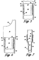
- Fig. 7 depicts an alternate embodiment of the present invention which include the cooperative means 52 as depicted in Figs. 2 and 4 .
- the embodiment of Fig. 7 includes an elongated substantially cylindrical extension 62 from the bottom of the distal end portion 34 of the mounting shaft 32.
- the extension 62 is coaxial with the mounting shaft and includes an outer sidewall 63 spaced from the inner surface of the pipette tip 40.
- the extension 62 functions to decrease the air volume captured in the pipette of the present invention and reduces the air volume effects commonly associated with air displacement pipettes.
- Figs. 11, 12, 13 and 14 resemble Figs. 4 , 5, 6, and 7 respectively and show alternative embodiments of the present invention where there is a small interference fit between the lateral support region 48 and support zone 38 to further enhance the lateral stability of the tip 40 on the shaft 32 without introducing an undesired increase in the axial forces required to mount and eject the tip from the shaft.
- Figs. 11, 12, 13 and 14 resemble Figs. 4 , 5, 6, and 7 respectively and show alternative embodiments of the present invention where there is a small interference fit between the lateral support region 48 and support zone 38 to further enhance the lateral stability of the tip 40 on the shaft 32 without introducing an undesired increase in the axial forces required to mount and eject the tip from the shaft.
- the lateral stability of the tip 40 on the shaft 32 can be further enhanced while maintaining the desired minimal tip mounting and ejection forces associated with the present invention when there is a small interference fit between the support region and zone.
- the small interference is provided by the lateral support region 48 of the tip 40 having an inner diameter which is slightly less than the outer diameter of the lateral support zone 38 of the shaft 32, e.g. less than .075 mm.
- a secondary air tight seal may be created between the support zone and region without creating an undesired increase in the axial forces required to mount and eject the tip on and from the shaft.
- the small interference fit is provided by controlling the axial taper of the sidewall of the tip between the sealing region and zone to taper slightly inwardly in a downward direction such that the sidewall of the tip engages the outside of the shaft in the support zone.
Landscapes
- Health & Medical Sciences (AREA)
- Clinical Laboratory Science (AREA)
- Chemical & Material Sciences (AREA)
- Chemical Kinetics & Catalysis (AREA)
- Devices For Use In Laboratory Experiments (AREA)
- Automatic Analysis And Handling Materials Therefor (AREA)
- Sampling And Sample Adjustment (AREA)
Claims (9)
- Luftverdrängungspipette (10) mit einem Pipettenspitzenbefestigungsschaft (32) und einer wegwerfbaren Pipettenspitze (40), die ein proximales Ende (42), das an dem Spitzenbefestigungsschaft befestigbar ist, und ein distales Probenaufnahmeende (44) aufweist, wobei der Schaft (32) im Wesentlichen zylindrische und axial beabstandete Außenflächenzonen besitzt, die eine ringförmige Dichtzone (36) und eine seitliche Stützzone (38) aufweisen, und die Spitze (40) entsprechende axial beabstandete Innenbereiche aufweist, die einen ringförmigen Dichtbereich (46) und einen seitlichen Stützbereich (48) aufweisen, wobei eine Seitenwand (50) in dem ringförmigen Dichtbereich (46) der Spitze (40) ringförmig und ausreichend dünn ausgebildet ist, so dass der Dichtbereich (46) sich geringfügig ausdehnt, um eine Presspassung und luftdichte Dichtung zwischen einer Dichtfläche (49) an der Innenfläche der Seitenwand und der Dichtzone (36) des Schafts (32) zu formen, wenn die Spitze (40) an dem Schaft (32) befestigt ist und die Dichtzone (36) in den Dichtbereich (46) eindringt,
wobei die Spitze dadurch gekennzeichnet ist, dass:der Dichtbereich (46) benachbart der Öffnung des proximalen Endes (42) der Spitze (40) angeordnet ist und der seitliche Stützbereich (48) nahe dem Ende des Schafts (32) liegt, wodurch ermöglicht wird,dass die Spitze (40) einem quergerichteten Wackeln und einem begleitenden unerwünschten Ablösen der Spitze (40) von dem Befestigungsschaft (32) widersteht. - Pipette nach Anspruch 1,
ferner gekennzeichnet durch:Niveaus an axialen Spitzenbefestigungs- und Ausstoßkräften, von denen es unwahrscheinlich ist, dass sie in einer Verletzung durch wiederholte Belastung eines Pipettenanwenders resultieren, der wiederholt und manuell die Spitzen (40) an dem Schaft (32) befestigt und die Spitzen (40) von dem Schaft (32) ausstößt. - Pipette nach Anspruch 1,
ferner gekennzeichnet durch:ein Mittel (52) zum Sicherstellen einer gleichförmigen Tiefe der Eindringung des Befestigungsschafts (32) in die Pipettenspitze (40), um einen gleichförmigen Spitzenpresssitz mit dem Befestigungsschaft (32) beizubehalten, wenn nachfolgende Spitzen (40) an dem Befestigungsschaft befestigt und von diesem ausgestoßen werden. - Pipette nach einem der Ansprüche 1 bis 3,
ferner dadurch gekennzeichnet, dass:die ringförmige Dichtzone (36) an dem Befestigungsschaft (32) einen Außendurchmesser aufweist, der geringfügig größer als ein Innendurchmesser des ringförmigen Dichtbereichs (46) an der Pipettenspitze ist. - Pipette nach einem der Ansprüche 1 bis 4,
ferner dadurch gekennzeichnet, dass:die Stützzone (38) an dem Befestigungsschaft (32) einen Außendurchmesser aufweist, der im Wesentlichen gleich einem Innendurchmesser des Stützbereichs (48) an der Pipettenspitze ist, um eine dichtungsfreie Abstützung für die Spitze an dem Schaft zu bilden. - Pipette nach Anspruch 5,
wobei die Seitenwand (50) der Pipettenspitze (40) in dem Dichtbereich (46) eine Dicke zwischen 0,2 und 0,5 mm besitzt. - Pipette nach einem der Ansprüche 5 oder 6,
wobei der Dichtbereich (46) einen Innendurchmesser besitzt, der etwa 0,075 mm bis etwa 0,2 mm kleiner als der Außendurchmesser der Dichtzone (36) ist, und wobei der Stützbereich (48) der Spitze (40) einen Innendurchmesser aufweist, der um 0,075 mm oder weniger kleiner als der Außendurchmesser der Stützzone (38) ist. - Pipette nach Anspruch 7,
wobei der Schaft (32) und die Spitze (40) konzentrisch und im Wesentlichen kreisförmig in der Stützzone (38) und dem Stützbereich (48) sind. - Pipette nach einem der Ansprüche 1 bis 8,
wobei die Pipettenspitze (40) eine einwärts gerichtete Schulter (53) zwischen dem proximalen Ende (42) und dem distalen Ende (44) aufweist und wobei der Dichtbereich (46) entfernter von der Schulter (53) ist, als der Stützbereich (48).
Applications Claiming Priority (3)
| Application Number | Priority Date | Filing Date | Title |
|---|---|---|---|
| US09/188,031 US6168761B1 (en) | 1998-11-06 | 1998-11-06 | Pipette with improved pipette tip and mounting shaft |
| US09/234,197 US6171553B1 (en) | 1998-11-06 | 1999-01-20 | Pipette with improved pipette tip and mounting shaft |
| EP99958813A EP1126916B1 (de) | 1998-11-06 | 1999-11-05 | Pipette mit verbesserter pipettenspitze und verbesserter montage-achse |
Related Parent Applications (2)
| Application Number | Title | Priority Date | Filing Date |
|---|---|---|---|
| EP99958813A Division EP1126916B1 (de) | 1998-11-06 | 1999-11-05 | Pipette mit verbesserter pipettenspitze und verbesserter montage-achse |
| EP99958813.0 Division | 1999-11-05 |
Publications (2)
| Publication Number | Publication Date |
|---|---|
| EP1884286A1 EP1884286A1 (de) | 2008-02-06 |
| EP1884286B1 true EP1884286B1 (de) | 2013-06-05 |
Family
ID=22691499
Family Applications (1)
| Application Number | Title | Priority Date | Filing Date |
|---|---|---|---|
| EP07019160.6A Expired - Lifetime EP1884286B1 (de) | 1998-11-06 | 1999-11-05 | Luftverschiebungspipette |
Country Status (4)
| Country | Link |
|---|---|
| US (3) | US6168761B1 (de) |
| EP (1) | EP1884286B1 (de) |
| KR (1) | KR100477059B1 (de) |
| DE (1) | DE69937896T2 (de) |
Families Citing this family (53)
| Publication number | Priority date | Publication date | Assignee | Title |
|---|---|---|---|---|
| DE19917375C2 (de) * | 1999-04-16 | 2001-09-27 | Hamilton Bonaduz Ag Bonaduz | Pipettiereinheit |
| EP1210978A4 (de) * | 1999-05-31 | 2004-12-15 | Bridgestone Corp | Pipettenvorrichtung |
| JP3750460B2 (ja) * | 2000-02-18 | 2006-03-01 | 日立工機株式会社 | 分注装置及び分注方法 |
| US7416704B2 (en) * | 2000-06-26 | 2008-08-26 | Vistalab Technologies, Inc. | Handheld pipette |
| US6749812B2 (en) * | 2000-06-26 | 2004-06-15 | Vistalab Technologies | Automatic pipette detipping |
| US6568288B2 (en) | 2001-06-29 | 2003-05-27 | Rainin Instrument, Llc | Pipette with improved pipette tip and mounting shaft |
| US7335337B1 (en) * | 2001-09-11 | 2008-02-26 | Smith James C | Ergonomic pipette tip and adapters |
| EP1438138B1 (de) * | 2001-10-16 | 2010-09-08 | Matrix Technologies Corporation | Hand-pipettiervorrichtung |
| US6967004B2 (en) * | 2001-10-30 | 2005-11-22 | Rainin Instrument, Llc | Pipette with improved pipette tip and mounting shaft |
| US6793891B2 (en) | 2002-04-08 | 2004-09-21 | Felxi Yiu | Pipettor and externally sealed pipette tip |
| US6780381B2 (en) * | 2002-04-08 | 2004-08-24 | Felix H. Yiu | Pipettor and externally sealed pipette tip |
| DE10222511B4 (de) * | 2002-05-22 | 2005-03-17 | Eppendorf Ag | Pipettenspitze |
| JP4317816B2 (ja) * | 2002-07-23 | 2009-08-19 | プロテダイン・コーポレーション | 材料取り扱い工具 |
| US20040071602A1 (en) * | 2002-10-15 | 2004-04-15 | Yiu Felix H. | Pipettor head adapter |
| US20060027033A1 (en) * | 2002-10-16 | 2006-02-09 | Richard Cote | Hand-held pipette employing voice recognition control |
| US7284454B2 (en) * | 2004-05-27 | 2007-10-23 | Matrix Technologies Corporation | Hand held pipette |
| US20050089450A1 (en) * | 2003-10-27 | 2005-04-28 | Integrated Instrument Services, Inc. | Pipette with multiple sealing zones |
| US7396512B2 (en) * | 2003-11-04 | 2008-07-08 | Drummond Scientific Company | Automatic precision non-contact open-loop fluid dispensing |
| DE102004003433B4 (de) * | 2004-01-21 | 2006-03-23 | Eppendorf Ag | Pipettiervorrichtung mit einer Abwurfeinrichtung für Pipettenspitzen |
| US7641859B2 (en) * | 2004-02-11 | 2010-01-05 | Matrix Technologies Corporation | Pipette tip mounting and ejection assembly and associated pipette tip |
| WO2006104905A1 (en) * | 2005-03-28 | 2006-10-05 | Indiana Proteomics Consortium, Llc | Device for holding a sample and subjecting the sample to chromatographic analysis |
| JP2007271427A (ja) * | 2006-03-31 | 2007-10-18 | Sysmex Corp | ピペットチップ |
| EP1862219B1 (de) * | 2006-05-29 | 2018-02-07 | Qiagen GmbH | Vorrichtung zur halterung von pipettenspitzen sowie pipettiervorrichtung |
| US20080078258A1 (en) * | 2006-09-28 | 2008-04-03 | Price West L | Multi-component pipette tip and associated methods |
| US7662343B2 (en) | 2006-10-24 | 2010-02-16 | Viaflo Corporation | Locking pipette tip and mounting shaft |
| US7662344B2 (en) | 2006-10-24 | 2010-02-16 | Viaflo Corporation | Locking pipette tip and mounting shaft |
| US20090071267A1 (en) * | 2007-09-17 | 2009-03-19 | Greg Mathus | Pipette tip ejection mechanism |
| JP2010538928A (ja) * | 2007-09-19 | 2010-12-16 | ソレンソン バイオサイエンス インコーポレーティッド | ピペットチップラックおよび関連方法 |
| USD620602S1 (en) | 2008-01-03 | 2010-07-27 | Vistalab Technologies, Inc. | Pipette |
| US8202495B1 (en) * | 2008-06-23 | 2012-06-19 | Smith James C | Ergonomic pipette tip |
| US8899118B1 (en) | 2009-05-11 | 2014-12-02 | Dan Seguin | Multi-channel aspirating and dispensing instrument |
| US8277757B2 (en) * | 2009-09-29 | 2012-10-02 | Integra Biosciences Corp. | Pipette tip mounting shaft |
| US8911145B2 (en) * | 2009-11-20 | 2014-12-16 | The United States Of America As Represented By The Secretary Of The Navy | Method to measure the characteristics in an electrical component |
| US9486803B2 (en) | 2010-01-22 | 2016-11-08 | Biotix, Inc. | Pipette tips |
| US8524170B2 (en) | 2011-02-22 | 2013-09-03 | Rainin Instrument, Llc | Pipette and sealing tip |
| US8795606B2 (en) | 2012-05-30 | 2014-08-05 | Biotix, Inc. | Integrated pipette tip devices |
| US9815053B2 (en) | 2013-01-15 | 2017-11-14 | Mettler-Toledo Rainin, LLC | Liquid end assembly for a multichannel air displacement pipette |
| USD731075S1 (en) | 2013-03-15 | 2015-06-02 | Nalge Nunc International Corporation | Pipette |
| US10343156B2 (en) | 2013-03-15 | 2019-07-09 | Nalge Nunc International Corporation | Tapered pipette |
| DE202013003390U1 (de) * | 2013-04-11 | 2014-07-14 | Brand Gmbh + Co Kg | Pipettiervorrichtung mit einer Mikrodosiereinheit |
| US10052626B2 (en) | 2013-04-30 | 2018-08-21 | Corning Incorporated | Pipette tip |
| USD703344S1 (en) | 2013-06-18 | 2014-04-22 | Corning Incorporated | Pipette tip |
| US9482215B2 (en) * | 2013-07-19 | 2016-11-01 | Norman Werbner Information Services, Inc. | Liquid extraction system with reduced exposure to air |
| USD805651S1 (en) * | 2013-12-12 | 2017-12-19 | Eppendorf Ag | Flange for a pipette adapter |
| US10525460B2 (en) | 2016-06-15 | 2020-01-07 | Hamilton Company | Pipetting device, pipette tip coupler, and pipette tip: devices and methods |
| US11065614B2 (en) | 2016-06-15 | 2021-07-20 | Hamilton Company | Pipetting device, pipette tip coupler, and pipette tip: devices and methods |
| US10898892B2 (en) | 2016-06-15 | 2021-01-26 | Hamilton Company | Pipetting device, pipette tip coupler, and pipette tip: devices and methods |
| US11235318B2 (en) | 2016-06-15 | 2022-02-01 | Hamilton Company | Pipetting device, pipette tip coupler, and pipette tip: devices and methods |
| US11193930B2 (en) | 2016-08-02 | 2021-12-07 | DPX Technologies, LLC | Automated protein precipitation and/or dispersive solid phase extraction using filter tips |
| US12287333B2 (en) | 2016-08-02 | 2025-04-29 | Dpx Technologies, Inc. | Automated solid phase extraction using filter tips |
| CN110944751B (zh) | 2017-05-17 | 2022-04-01 | 拜欧迪克斯公司 | 人体工学移液管吸头 |
| US10384841B2 (en) | 2017-06-29 | 2019-08-20 | Norman Werbner Information Services, Inc. | Liquid extraction, storage, and dispensing system and method of use |
| JP7802656B2 (ja) * | 2020-01-15 | 2026-01-20 | レヴィティ ヘルス サイエンシズ インコーポレイテッド | ピペット・チップ並びにそれを含む方法及びシステム |
Family Cites Families (11)
| Publication number | Priority date | Publication date | Assignee | Title |
|---|---|---|---|---|
| US188030A (en) | 1877-03-06 | Improvement in fences | ||
| US3732734A (en) * | 1972-05-25 | 1973-05-15 | Centaur Chemical Co | Micropipette with disposable tips |
| FR2287941A1 (fr) | 1974-10-15 | 1976-05-14 | Marteau D Autry Eric | Dispositif d'ejection de l'embout amovible d'une pipette |
| DE2526296C3 (de) * | 1975-06-12 | 1978-05-18 | Eppendorf Geraetebau Netheler + Hinz Gmbh, 2000 Hamburg | Aufsteckbare Pipettenspitze |
| US4187724A (en) * | 1978-01-11 | 1980-02-12 | Indicon Inc. | Replaceable tip for a pipette |
| FI843976L (fi) * | 1983-10-13 | 1985-04-14 | Cetus Corp | Utbytbar pipettspets. |
| US4824641A (en) * | 1986-06-20 | 1989-04-25 | Cetus Corporation | Carousel and tip |
| US4748859A (en) * | 1987-03-06 | 1988-06-07 | Rainin Instrument Co., Inc. | Disposable pipette tip |
| DE3824767A1 (de) * | 1988-07-21 | 1990-02-01 | Eppendorf Geraetebau Netheler | Aufsteckbare pipettenspitze in form eines entsprechend einem aufsteckkopfstueck, insbesondere konus einer pipette, wenigstens abschnittsweise ausgefuehrten gefaesses |
| US5232669A (en) * | 1991-11-08 | 1993-08-03 | Abbott Laboratories | Pipette tip with self-aligning and self-sealing features |
| US5779984A (en) | 1996-12-04 | 1998-07-14 | Rainin Intstrumental Co., Inc. | Pipette tip rack and refill pack containing large maximized volume freely nestable pipette tips |
-
1998
- 1998-11-06 US US09/188,031 patent/US6168761B1/en not_active Expired - Lifetime
-
1999
- 1999-01-20 US US09/234,197 patent/US6171553B1/en not_active Expired - Lifetime
- 1999-11-05 EP EP07019160.6A patent/EP1884286B1/de not_active Expired - Lifetime
- 1999-11-05 DE DE69937896T patent/DE69937896T2/de not_active Expired - Lifetime
- 1999-11-05 KR KR10-2001-7005691A patent/KR100477059B1/ko not_active Expired - Lifetime
-
2000
- 2000-10-06 US US09/680,854 patent/US6737023B1/en not_active Expired - Lifetime
Also Published As
| Publication number | Publication date |
|---|---|
| DE69937896T2 (de) | 2009-01-02 |
| US6737023B1 (en) | 2004-05-18 |
| DE69937896D1 (de) | 2008-02-14 |
| US6171553B1 (en) | 2001-01-09 |
| US6168761B1 (en) | 2001-01-02 |
| EP1884286A1 (de) | 2008-02-06 |
| KR20010083953A (ko) | 2001-09-03 |
| KR100477059B1 (ko) | 2005-03-17 |
Similar Documents
| Publication | Publication Date | Title |
|---|---|---|
| EP1884286B1 (de) | Luftverschiebungspipette | |
| US6745636B2 (en) | Pipette with improved pipette tip and mounting shaft | |
| US6967004B2 (en) | Pipette with improved pipette tip and mounting shaft | |
| US6197259B1 (en) | Easy eject pipette tip | |
| US6248295B1 (en) | Pipette with improved pipette tip and mounting shaft combination | |
| US5807524A (en) | Pipette tip with pipette surface contamination protector | |
| JP2011502752A (ja) | 固定ピペットチップ及び取り付けシャフト | |
| US9156030B2 (en) | Pipette tip | |
| EP1240493A1 (de) | Adaptierbare pipette | |
| EP1126916B1 (de) | Pipette mit verbesserter pipettenspitze und verbesserter montage-achse | |
| US12303883B2 (en) | Pipette for use with a pipette tip with an integrated plunger | |
| CN111408422B (zh) | 用于与移液器末端件一起使用的移液器 | |
| JPH0457377B2 (de) | ||
| EP1135210B1 (de) | Pipette mit verbesserter pipettenspitze und verbessertem montage-achsen-system | |
| US20220401945A1 (en) | Pipette tip family comprising pipette tips for use with pipettes of a pipette family and pipette family comprising pipettes for use with pipette tips of a pipette tip family | |
| MXPA01004565A (en) | Pipette with improved pipette tip and mounting shaft | |
| US20260108873A1 (en) | Pipette tip and mounting shaft with offset locking feature | |
| WO2026088113A2 (en) | Pipette tip and mounting shaft with offset locking feature | |
| MXPA01004452A (en) | Pipette with improved pipette tip and mounting shaft combination |
Legal Events
| Date | Code | Title | Description |
|---|---|---|---|
| PUAI | Public reference made under article 153(3) epc to a published international application that has entered the european phase |
Free format text: ORIGINAL CODE: 0009012 |
|
| AC | Divisional application: reference to earlier application |
Ref document number: 1126916 Country of ref document: EP Kind code of ref document: P |
|
| AK | Designated contracting states |
Kind code of ref document: A1 Designated state(s): AT BE CH CY DE DK ES FI FR GB GR IE IT LI LU MC NL PT SE |
|
| 17P | Request for examination filed |
Effective date: 20080806 |
|
| AKX | Designation fees paid |
Designated state(s): AT BE CH CY DE DK ES FI FR GB GR IE IT LI LU MC NL PT SE |
|
| 17Q | First examination report despatched |
Effective date: 20080908 |
|
| GRAP | Despatch of communication of intention to grant a patent |
Free format text: ORIGINAL CODE: EPIDOSNIGR1 |
|
| GRAS | Grant fee paid |
Free format text: ORIGINAL CODE: EPIDOSNIGR3 |
|
| GRAA | (expected) grant |
Free format text: ORIGINAL CODE: 0009210 |
|
| AC | Divisional application: reference to earlier application |
Ref document number: 1126916 Country of ref document: EP Kind code of ref document: P |
|
| AK | Designated contracting states |
Kind code of ref document: B1 Designated state(s): AT BE CH CY DE DK ES FI FR GB GR IE IT LI LU MC NL PT SE |
|
| REG | Reference to a national code |
Ref country code: GB Ref legal event code: FG4D |
|
| REG | Reference to a national code |
Ref country code: CH Ref legal event code: NV Representative=s name: DR. GRAF AND PARTNER AG INTELLECTUAL PROPERTY, CH Ref country code: CH Ref legal event code: EP |
|
| REG | Reference to a national code |
Ref country code: AT Ref legal event code: REF Ref document number: 615314 Country of ref document: AT Kind code of ref document: T Effective date: 20130615 |
|
| REG | Reference to a national code |
Ref country code: IE Ref legal event code: FG4D |
|
| REG | Reference to a national code |
Ref country code: DE Ref legal event code: R096 Ref document number: 69944775 Country of ref document: DE Effective date: 20130801 |
|
| PG25 | Lapsed in a contracting state [announced via postgrant information from national office to epo] |
Ref country code: SE Free format text: LAPSE BECAUSE OF FAILURE TO SUBMIT A TRANSLATION OF THE DESCRIPTION OR TO PAY THE FEE WITHIN THE PRESCRIBED TIME-LIMIT Effective date: 20130605 Ref country code: ES Free format text: LAPSE BECAUSE OF FAILURE TO SUBMIT A TRANSLATION OF THE DESCRIPTION OR TO PAY THE FEE WITHIN THE PRESCRIBED TIME-LIMIT Effective date: 20130916 Ref country code: GR Free format text: LAPSE BECAUSE OF FAILURE TO SUBMIT A TRANSLATION OF THE DESCRIPTION OR TO PAY THE FEE WITHIN THE PRESCRIBED TIME-LIMIT Effective date: 20130906 |
|
| REG | Reference to a national code |
Ref country code: NL Ref legal event code: VDEP Effective date: 20130605 |
|
| PG25 | Lapsed in a contracting state [announced via postgrant information from national office to epo] |
Ref country code: PT Free format text: LAPSE BECAUSE OF FAILURE TO SUBMIT A TRANSLATION OF THE DESCRIPTION OR TO PAY THE FEE WITHIN THE PRESCRIBED TIME-LIMIT Effective date: 20131007 Ref country code: BE Free format text: LAPSE BECAUSE OF FAILURE TO SUBMIT A TRANSLATION OF THE DESCRIPTION OR TO PAY THE FEE WITHIN THE PRESCRIBED TIME-LIMIT Effective date: 20130605 |
|
| PG25 | Lapsed in a contracting state [announced via postgrant information from national office to epo] |
Ref country code: NL Free format text: LAPSE BECAUSE OF FAILURE TO SUBMIT A TRANSLATION OF THE DESCRIPTION OR TO PAY THE FEE WITHIN THE PRESCRIBED TIME-LIMIT Effective date: 20130605 |
|
| PLBE | No opposition filed within time limit |
Free format text: ORIGINAL CODE: 0009261 |
|
| STAA | Information on the status of an ep patent application or granted ep patent |
Free format text: STATUS: NO OPPOSITION FILED WITHIN TIME LIMIT |
|
| PG25 | Lapsed in a contracting state [announced via postgrant information from national office to epo] |
Ref country code: DK Free format text: LAPSE BECAUSE OF FAILURE TO SUBMIT A TRANSLATION OF THE DESCRIPTION OR TO PAY THE FEE WITHIN THE PRESCRIBED TIME-LIMIT Effective date: 20130605 |
|
| 26N | No opposition filed |
Effective date: 20140306 |
|
| REG | Reference to a national code |
Ref country code: DE Ref legal event code: R097 Ref document number: 69944775 Country of ref document: DE Effective date: 20140306 |
|
| PG25 | Lapsed in a contracting state [announced via postgrant information from national office to epo] |
Ref country code: MC Free format text: LAPSE BECAUSE OF FAILURE TO SUBMIT A TRANSLATION OF THE DESCRIPTION OR TO PAY THE FEE WITHIN THE PRESCRIBED TIME-LIMIT Effective date: 20130605 |
|
| REG | Reference to a national code |
Ref country code: IE Ref legal event code: MM4A |
|
| PG25 | Lapsed in a contracting state [announced via postgrant information from national office to epo] |
Ref country code: IE Free format text: LAPSE BECAUSE OF NON-PAYMENT OF DUE FEES Effective date: 20131105 |
|
| REG | Reference to a national code |
Ref country code: AT Ref legal event code: MM01 Ref document number: 615314 Country of ref document: AT Kind code of ref document: T Effective date: 20131105 |
|
| PG25 | Lapsed in a contracting state [announced via postgrant information from national office to epo] |
Ref country code: AT Free format text: LAPSE BECAUSE OF NON-PAYMENT OF DUE FEES Effective date: 20131105 |
|
| PG25 | Lapsed in a contracting state [announced via postgrant information from national office to epo] |
Ref country code: CY Free format text: LAPSE BECAUSE OF FAILURE TO SUBMIT A TRANSLATION OF THE DESCRIPTION OR TO PAY THE FEE WITHIN THE PRESCRIBED TIME-LIMIT Effective date: 20130605 |
|
| PG25 | Lapsed in a contracting state [announced via postgrant information from national office to epo] |
Ref country code: LU Free format text: LAPSE BECAUSE OF NON-PAYMENT OF DUE FEES Effective date: 20131105 |
|
| REG | Reference to a national code |
Ref country code: FR Ref legal event code: PLFP Year of fee payment: 17 |
|
| REG | Reference to a national code |
Ref country code: FR Ref legal event code: PLFP Year of fee payment: 18 |
|
| REG | Reference to a national code |
Ref country code: FR Ref legal event code: PLFP Year of fee payment: 19 |
|
| REG | Reference to a national code |
Ref country code: DE Ref legal event code: R082 Ref document number: 69944775 Country of ref document: DE Representative=s name: MANITZ FINSTERWALD PATENT- UND RECHTSANWALTSPA, DE Ref country code: DE Ref legal event code: R082 Ref document number: 69944775 Country of ref document: DE Representative=s name: MANITZ FINSTERWALD PATENTANWAELTE PARTMBB, DE Ref country code: DE Ref legal event code: R081 Ref document number: 69944775 Country of ref document: DE Owner name: METTLER-TOLEDO RAININ, LLC (N.D.GES.D. STAATES, US Free format text: FORMER OWNER: RAININ INSTRUMENT LLC., OAKLAND, CALIF., US |
|
| REG | Reference to a national code |
Ref country code: FR Ref legal event code: PLFP Year of fee payment: 20 |
|
| REG | Reference to a national code |
Ref country code: CH Ref legal event code: PFA Owner name: METTLER-TOLEDO RAININ, LLC, US Free format text: FORMER OWNER: RAININ INSTRUMENT LLC., US |
|
| REG | Reference to a national code |
Ref country code: AT Ref legal event code: HC Ref document number: 615314 Country of ref document: AT Kind code of ref document: T Owner name: METTLER-TOLEDO RAININ, LLC., US Effective date: 20181121 |
|
| PGFP | Annual fee paid to national office [announced via postgrant information from national office to epo] |
Ref country code: FI Payment date: 20181026 Year of fee payment: 20 Ref country code: DE Payment date: 20181015 Year of fee payment: 20 |
|
| PGFP | Annual fee paid to national office [announced via postgrant information from national office to epo] |
Ref country code: CH Payment date: 20181030 Year of fee payment: 20 Ref country code: GB Payment date: 20181025 Year of fee payment: 20 Ref country code: IT Payment date: 20181119 Year of fee payment: 20 Ref country code: FR Payment date: 20181017 Year of fee payment: 20 |
|
| REG | Reference to a national code |
Ref country code: DE Ref legal event code: R071 Ref document number: 69944775 Country of ref document: DE |
|
| REG | Reference to a national code |
Ref country code: CH Ref legal event code: PL |
|
| REG | Reference to a national code |
Ref country code: GB Ref legal event code: PE20 Expiry date: 20191104 |
|
| PG25 | Lapsed in a contracting state [announced via postgrant information from national office to epo] |
Ref country code: GB Free format text: LAPSE BECAUSE OF EXPIRATION OF PROTECTION Effective date: 20191104 |