EP1884429A2 - Dispositif de préparation de l'air comprimé destiné à alimenter une installation de freinage d'un véhicule automobile avec de l'air comprimé - Google Patents
Dispositif de préparation de l'air comprimé destiné à alimenter une installation de freinage d'un véhicule automobile avec de l'air comprimé Download PDFInfo
- Publication number
- EP1884429A2 EP1884429A2 EP07014783A EP07014783A EP1884429A2 EP 1884429 A2 EP1884429 A2 EP 1884429A2 EP 07014783 A EP07014783 A EP 07014783A EP 07014783 A EP07014783 A EP 07014783A EP 1884429 A2 EP1884429 A2 EP 1884429A2
- Authority
- EP
- European Patent Office
- Prior art keywords
- compressed air
- valve
- connection
- consumer
- service brake
- Prior art date
- Legal status (The legal status is an assumption and is not a legal conclusion. Google has not performed a legal analysis and makes no representation as to the accuracy of the status listed.)
- Granted
Links
Images



Classifications
-
- B—PERFORMING OPERATIONS; TRANSPORTING
- B60—VEHICLES IN GENERAL
- B60T—VEHICLE BRAKE CONTROL SYSTEMS OR PARTS THEREOF; BRAKE CONTROL SYSTEMS OR PARTS THEREOF, IN GENERAL; ARRANGEMENT OF BRAKING ELEMENTS ON VEHICLES IN GENERAL; PORTABLE DEVICES FOR PREVENTING UNWANTED MOVEMENT OF VEHICLES; VEHICLE MODIFICATIONS TO FACILITATE COOLING OF BRAKES
- B60T17/00—Component parts, details, or accessories of power brake systems not covered by groups B60T8/00, B60T13/00 or B60T15/00, or presenting other characteristic features
- B60T17/02—Arrangements of pumps or compressors, or control devices therefor
-
- B—PERFORMING OPERATIONS; TRANSPORTING
- B60—VEHICLES IN GENERAL
- B60T—VEHICLE BRAKE CONTROL SYSTEMS OR PARTS THEREOF; BRAKE CONTROL SYSTEMS OR PARTS THEREOF, IN GENERAL; ARRANGEMENT OF BRAKING ELEMENTS ON VEHICLES IN GENERAL; PORTABLE DEVICES FOR PREVENTING UNWANTED MOVEMENT OF VEHICLES; VEHICLE MODIFICATIONS TO FACILITATE COOLING OF BRAKES
- B60T15/00—Construction arrangement, or operation of valves incorporated in power brake systems and not covered by groups B60T11/00 or B60T13/00
- B60T15/02—Application and release valves
- B60T15/36—Other control devices or valves characterised by definite functions
- B60T15/48—Other control devices or valves characterised by definite functions for filling reservoirs
Definitions
- the invention relates to a compressed air treatment device for supplying a motor vehicle brake system with compressed air, with two provided for supplying a service brake service brake terminals, a Mautexerventil for controlling the compressed air supply to at least one Mauvoneran gleich, a Mautexer pilot valve to supply a control input of the secondary consumer valve optionally compressed air via a serial supply line, said the serial supply line is connected to a connection point connected to both service brake terminals.
- a compressed air treatment device is known.
- a pressure limiter is provided between the pressure control unit and the pressure control output, which limits the pressure to a predetermined outlet pressure even in the de-energized state. Furthermore, it is possible to work in the individual consumer circuits with different pressures. The individual consumer circuits are connected in parallel to the main supply line.
- a serial supply line is connected to the two service brake connections 21 and 22 by means of a shuttle valve 80.
- a shuttle valve 80 With such a construction, there is a risk that in the event of a slight leak in one of the two service brake circuits, the other service brake circuit will be affected. A slight leakage has the consequence that in the corresponding brake circuit pressure is still present, even if it is slightly reduced. The only slightly reduced pressure in one of the brake circuits does not allow that the shuttle valve 80 completely closes this brake circuit, so that there is the possibility that overflowed from the intact brake circuit via the shuttle valve 80 air in the leaking brake circuit.
- the compressed air treatment device is based on the generic state of the art in that a check valve is provided in each case between the service brake connections and the connection point. Through this structure, an overflow of compressed air is completely prevented by an intact brake circuit to a possibly slightly leaking brake circuit. This leads to a safe braking force provision and a compressed air treatment device with improved efficiency, since a leak, even if it is very small, is completely completed.
- Another advantage of this circuit is that, when using the "Northland Parkbrake Function" explained later, in particular, the sub-consumer pilot valve from service brake tanks, which are connected to the service brake ports during operation, can be supplied with compressed air when the pressure in the compressed air system after the Vehicle was parked, has dropped by small leaks under the closing pressures of circuit protection valves, preferably overflow valves.
- the compressed air treatment device can be further developed in an advantageous manner in that a service brake valve is arranged upstream of the service brake connections and is arranged such that its output side facing the service brake connections is connected to the connection point. These valves can be used to protect the service brake circuits in the event of leakage.
- the service brake valves are overflow valves.
- Overflow valves in front of the service brake circuits is a safe way to safeguard the service brake circuits. As soon as a leak occurs, the pressure in the corresponding wiring harness drops below the closing pressure of the overflow valve, so that the overflow valve closes and separates the corresponding service brake circuit from a compressed air supply line.
- an input side of a secondary consumer pressure limiter connected upstream of the auxiliary consumer connection is coupled to the serial supply line.
- the compressed air treatment device according to the invention can be developed such that an input side of a secondary consumer pressure limiter connected upstream of the secondary consumer connection is coupled to a main line.
- the compressed air treatment device according to the invention can be developed such that an additional consumer connection and a transmission circuit connection parallel to each other to the output side of the secondary consumer pressure limiter are coupled. By connecting these consumers they are supplied with a reduced pressure level. Thus, the requirement of vehicle manufacturers to provide different pressure levels can be accommodated.
- an additional consumer connection and a transmission circuit connection are provided, wherein a supply line to the additional consumer connection is coupled to the output side of the auxiliary consumer pressure limiter and a supply line to the transmission circuit connection is connected to the input side of the auxiliary consumer pressure limiter.
- This arrangement provides a higher pressure level for the transmission circuit, whereas for the remaining consumers a reduced pressure level is provided.
- the compressed air treatment device can be further developed in that an additional consumer connection and a transmission circuit connection are provided, wherein the supply line is coupled to one of the two connections to an output side of a valve, which is connected upstream of the other of the two connections.
- the supply of a consumer can be equipped with a higher priority than the supply of another consumer. This achieves a variable priority of two compressed air outputs to each other.
- the compressed air processing device can be configured such that the auxiliary consumer connection has at least one connection from the group which also has a trailer connection for supplying a trailer brake system Compressed air and a parking brake connection for supplying a parking brake for releasing this includes. This specifies a specification of the intended consumers.
- the invention provides a motor vehicle with a compressed air treatment device according to the invention.
- This vehicle provides the advantages described above in a metaphorical manner.
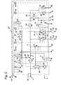
- FIG. 1 shows a circuit diagram of a first exemplary embodiment of a compressed air treatment device according to the invention.
- the compressed air treatment device according to the invention has a compressed air inlet 1, the compressed air from a compressor, not shown, can be fed. Parallel to the compressed air inlet 1, a foreign filling port 12 is provided, via which the compressed air system of the commercial vehicle can be filled, for example, in a workshop without the operation of the compressor. Compressed air is supplied via the compressed air inlet 1 to an air dryer unit 2 and from there via a check valve 5 and a main line 6 to the later-described compressed air consumers.
- the check valve 5 is provided to prevent a backflow of compressed air from the consumers in the direction of the air dryer unit 2, which is preferably a spring-biased check valve, which allows a flow only after reaching a certain pressure threshold.
- a line leading to a tire inflation port 28 branches off, in which a tire inflation valve 7 is arranged.
- the tire inflation valve 7 is preferably a 2/2-way valve with manual operation and can be switched from a closed to an open position, if necessary, to remove via the tire inflation 28 compressed air for filling vehicle tires.
- an air suspension valve 8 is arranged in a line branching from the main line 6 and leading to an air suspension connection 27.
- the air suspension valve 8 is preferably an overflow valve, so that when connected to the main line 6 input of the Lucasfederungsventils 8, the compressed air exceeds a certain predetermined opening pressure, the air suspension valve 8 switches from a closed to an open position and an overflow of compressed air from the main line 6 to the air suspension port 27 allowed.
- the air suspension valve 8 remains in an open state until a closing pressure is exceeded, wherein the closing pressure is smaller than the opening pressure.
- This general mode of operation of this overflow valve also applies in a transferred manner to the overflow valves described below.
- the overflow valves thus act as circular safety valves to secure the operating circuits that are downstream of them.
- This fuse is effected by the overflow valves close, as soon as the pressure in the corresponding wiring harness drops below the closing pressure, ie in the event of leakage and the associated pressure drop in this wiring harness, this wiring harness is disconnected from the compressed air supply and the other circuits.
- two parallel service brake valves 9 and 10 which are preferably overflow valves.
- the output sides of the service brake valves 9 and 10 each lead to a service brake port 21, 22.
- the service brake ports 21, 22 each lead to a service brake tank 13, 14 to which the service brake circuits 15, 16 are connected.
- a respective line branches off between the respective service brake valves 9, 10 and their corresponding service brake connections 21, 22, with both lines meeting at a connection point 11.
- Check valves 17, 18 are respectively disposed between the branches and the connection point 11, each allowing a flow of compressed air to the connection point 11 and prevent flow in the reverse direction.
- a serial supply line 19 branches off, which supplies further consumers explained below with compressed air.
- an input of a slave consumer pressure limiter 20 is coupled to the serial supply line 19.
- the output of the secondary consumer pressure limiter 20 is connected to a secondary consumer line 29, from which a line branches off, which leads to a trailer connection 23 and in which a secondary consumer valve 30 is arranged.
- the secondary consumer valve 30 is preferably designed as a pressure relief valve whose switching behavior is adjustable by means of a control input.
- a trailer brake system not shown, can be connected.
- a check valve 31 is provided which allows only a flow in the direction of the parking brake port 25.
- the check valve 31 is preferably a spring-biased check valve, so that a flow through the check valve 31 is allowed only after reaching a certain threshold.
- a parking brake is released from the locked position.
- check valve 31 and parking brake port 25 branches off to a vent 3 leading line into which a check valve 32 is connected.
- the check valve 32 opens from a certain, adjustable threshold, thus protecting the line connected to the parking brake port 25 from excessive pressure.
- the threshold value for opening the check valve 32 is set higher than the corresponding threshold of the check valve 31.
- the check valve 32 thus acts as a safety valve, the expert safety valves with other configurations are known in the art, which are not further explained at this point.
- the control line of the valve 53 is connected to the line between the service brake valve 10 and the service brake port 22, so that depending on the pressure at the service brake port 22, the valve 53 either switches to a closed position in which it prevents compressed air from flowing to the trailer port 23 connected trailer brake system for venting flows while the valve 53 in another switching state allows a throttled outflow of compressed air from the trailer brake system connected to the trailer connection 23 to the vent 3.
- valve 53 When pressure is applied to the service brake connection 22, the valve 53 switches into its closed position.
- the control input of the valve 53 may also be connected to the service brake connection 21 instead of the service brake connection 22.
- two parallel lines branch off from the secondary consumer line 29, one of which leads to an additional consumer connection 24 and the other to a transmission circuit connection 26.
- a supplementary consumer valve 33 is provided, while a transmission circuit valve 34 is arranged between the secondary consumer line 29 and the transmission circuit connection 26. Both valves are preferably overflow valves.
- Reference numeral 35 denotes an electronic control unit (ECU) for controlling the operation of the air treatment device.
- ECU electronice control unit
- the electronic control unit 35 is connected to a central plug 36, via which the electronic control unit 35 can be connected, for example, to a CAN bus 37 in order to form an interface to the other vehicle electronics. Furthermore, an optional humidifier 38 is provided, via which a signal of an external, not shown, humidity sensor can be read. This is usually at the lowest point of the service brake tank 13, 14 attached. Furthermore, a heater 39 and a temperature sensor 40 are connected to the electronic control unit 35.
- various pressure sensors 41-45 are connected to the electronic control unit 35, wherein the pressure sensor 41 a pressure at the air suspension port 27, the pressure sensor 42, a pressure at the service brake port 21, the Pressure sensor 43 detects a pressure at the service brake port 22, the pressure sensor 44, a pressure at the trailer connection 23 and the pressure sensor 45, a pressure at the transmission circuit connection 26 and fed into the electronic control unit 35 for evaluation.
- a secondary consumer pilot valve 46 is connected, which is designed as a 3/2-way solenoid valve. In the switching position shown in Figure 1, the secondary consumer pilot valve 46 connects a control input of the secondary consumer valve 30 with the vent 3.
- the secondary consumer pilot valve 46 connects the control input of the secondary consumer valve 30 with the serial supply line 19, whereby the in the serial supply line 19 is applied to the control input of the secondary consumer valve 30 and this secondary consumer valve 30 then prevents an overflow of compressed air from the secondary consumer line 29 to the trailer connection 23 and the parking brake connection 25.
- the secondary consumer pilot valve 46 is energized, so that the control input of the secondary consumer valve 30 compressed air is supplied. This is to prevent prematurely released handbrake in a state in which not enough pressure is built, the vehicle is first braked by the parking brake and in the course of pressure build-up, if the driver may not be in the driver's seat, the vehicle automatically starts to roll.
- a regeneration valve 47 is provided, which is designed as a 3/2-way solenoid valve.
- the regeneration valve 47 is connected in series with a check valve 48 and a throttle 49.
- the check valve 48 avoids during the delivery phases of the compressor, an overflow of compressed air via the regeneration valve 47 for vent 3.
- the throttle 49 is provided to limit the flow rate in a regeneration favoring manner.
- a control line is connected, which leads to a discharge valve 50.
- the control line of the drain valve 50 is connected to the vent 3
- the check valve 48 prevents compressed air flows over the regeneration valve 47 to the vent 3 during the delivery phases of the compressor.
- the regeneration valve 47 connects the control line of the discharge valve 50 to the pressure prevailing in the serial supply line 19. In addition, this pressure is also applied to the connection line between air dryer unit 2 and check valve 5.
- the drain valve 50 is connected between the inlet side of the air dryer unit 2 and the vent 3.
- a pressure regulator solenoid valve 51 is provided, which is designed as a 3/2-way solenoid valve and is controlled by the electronic control unit 35. Via the pressure regulator solenoid valve 51, a compressor control output 4 via a control valve 52 of the pressure prevailing in the serial supply line 19 pressure can be supplied. In addition to the pressure supply to the compressor control output 4, the same pressure can be applied by means of the pressure regulator solenoid valve 51 to a further control input of the drain valve 50.
- the discharge valve 50 is designed so that when a pressure applied to the control input, which is switched by means of the pressure regulator solenoid valve 51, the discharge valve 50 is switched in any case in the open switching position.
- the control valve 52 is designed so that it connects the compressor control output 4 with the vent 3 in the absence of pressurization by the pressure regulator solenoid valve 51, thus providing rapid venting and thus safe operation of the compressor with regard to its recommissioning becomes.
- Another connection of the control valve 52 is connected between the vent 3 and the drain valve 50 and thus connected to the vent 3.
- a collecting container 58 is provided, which is to represent an interior of the housing of the electronic control unit 35. Via a pressure compensation element 59 of the collecting tank 58 is connected to the vent 3 to pressure fluctuations within the housing the electronic control unit 35 compensate.
- the pressure compensation element 59 can be traversed by air, but not by liquids, and should protect the housing from damage that may otherwise be caused by pressure fluctuations due to altitude or temperature differences.
- the collecting container 58 is additionally provided with a check valve 60 to compensate for pressure increases in the housing of the electronic control unit 35, which exceed the maximum flow rate of the pressure compensation element 59. In this case, the check valve is arranged so that only one flow from the sump 58 to the vent 3 is made possible.
- the illustrated compressed air treatment device operates as follows.
- the compressor delivers compressed air into the compressed air inlet 1. Consequently, compressed air passes through the air dryer unit 2 via the check valve 5 to the main line 6.
- the overflow valves 8, 9 and 10 Upon reaching a predetermined pressure in the main line 6 allow the overflow valves 8, 9 and 10, an overflow of compressed air so that via the check valves 17, 18 finally also on the serial supply line 19 a certain pressure prevails.
- the air dryer unit 2 is charged with moisture and foreign particles, such as compressor oil and its decomposition products.
- the regeneration valve 47 and the pressure regulator solenoid valve 51 are transferred to their position not shown, so that on the one hand via the regeneration valve 47, the regeneration air flow through the check valve 48, the throttle 49, the air dryer unit 2 due to the switching of the pressure regulator solenoid valve 51 also switched drain valve 50 and the vent 3 can be done.
- the compressor control output 4 is pressurized, so that during the regeneration operation, the compressor remains switched off.
- the regeneration valve 47 and the pressure regulator solenoid valve 51 are again transferred to their illustrated positions, so that the control inputs associated with them are vented, wherein the venting of the compressor control input 4 directly without a detour can be done via a regeneration valve.
- Figure 2 shows a circuit diagram of a second embodiment of a compressed air treatment device according to the invention. 1 differs from the compressed air processing device shown in FIG. 1 in that the input side of the secondary consumer pressure limiter 20 is not connected to the serial supply line 19 as in the exemplary embodiment of FIG. 1, but instead to the main line 6. Pressure limiter 20 downstream consumers no longer connected in series with the service brake valves 9 and 10, but in parallel to these.
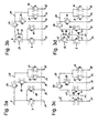
- FIGS. 3a to 5c different circuit variants of the circuits of the first and second are shown Embodiment shown.
- Table 1 below illustrates which circuit variants can be combined with each other.
- Table 1 Sub-consumer pilot valve 46 in serial series connection with serial supply line 19 Fig. 5a Fig. 5b Fig. 5c Fig. 3a Yes Yes Yes Yes Yes Fig. 3b Yes Yes Yes Yes Yes Yes Fig. 3c Yes Yes Yes Yes Yes Yes Yes Yes Yes Fig. 4a Yes Yes Yes No No Fig. 4b Yes Yes No No No Fig. 4c Yes Yes No No No
- FIG. 3a shows a circuit variant of the circuits of the first and second embodiments.
- the consumers downstream of the secondary pressure limiter 20 are connected in parallel to the consumer upstream of the secondary consumer pressure limiter 20.
- this circuit arrangement prevail two pressure levels, wherein a first level at an input side of the secondary consumer pressure limiter 20 and in the main line 6 is applied and a second pressure level at the output side and thus in the secondary consumer line 29 is applied.
- FIG. 3b shows a further circuit variant of the circuits of the first and second exemplary embodiments.
- the circuit variant of Figure 3b has a pressure limiter 54 which is between main line 6 and input side the service brake valves 9, 10 is arranged.
- the pressure limiter 54 is a series circuit of a throttle 55 and a check valve 56 connected in parallel, wherein the check valve 56 is oriented so that only a flow from the output side, ie the side connected to the service brake valves 9, 10 side, allowed to the main line 6 becomes.
- the line strands leading to the service brake connections 21, 22 are again connected in parallel to the line strands which lead to the trailer connection 23, to the additional consumer connection 24 and to the transmission circuit connection 26.
- the circuit therefore has three pressure levels, wherein a first pressure level in the main line 6, a second pressure level on the output side of the secondary consumer pressure limiter 20 (and thus in the secondary consumer line 29) and a third pressure level on the output side of the pressure limiter 54 prevails.
- FIG. 3 c shows a further circuit variant of the circuits of the first and second exemplary embodiments.
- the line strands which lead to the trailer connection 23, to the additional consumer connection 24 and to the transmission circuit connection 26 are connected in series to the line strands which lead to the service brake connections 21, 22.
- the input side of the secondary consumer pressure limiter 20 is only then pressurized after the service brake valves 9, 10 allow an overflow of compressed air and thus rests on the service brake ports 21, 22 compressed air.
- FIG. 3d shows a further circuit variant of the circuits of the first and second exemplary embodiments.
- a pressure limiter 54 is provided with the parallel series connection of inductor 55 and check valve 56.
- the pressure limiter 54 is provided between the main line 6 and the input side of the service brake valves 9, 10.
- the line strands to the consumers, which are connected downstream of the auxiliary consumer pressure limiter 20, are connected downstream of the line strands to the service brake connections 21, 22.
- compressed air is applied to the input side of the secondary consumer pressure limiter 20 only after compressed air has been applied to the service brake connections 21, 22.
- FIG. 4a shows a further circuit variant of the circuits of the first and second embodiments.
- the line strands to the service brake ports 21, 22 parallel to the leading to the transmission circuit connection 26 wiring harness and connected to the trailer connection 23 and the additional consumer connection 24 leading strand.
- the line leading to the transmission circuit connection 26 is not branched off from the secondary consumer line 29, but from the main line 6.
- a transmission circuit pressure limiter 57 is interposed between the main line 6 and gear shift valve 34.
- a first pressure level prevails in the main line 6 and thus on the input side of the secondary consumer pressure limiter 20 and the input side of the gearshift pressure limiter 57.
- a second pressure level prevails on the output side of the secondary consumer pressure limiter 20 and thus also in the secondary consumer line 29.
- a third pressure level is formed on the output side of the transmission shift pressure limiter 57 and thus also on the transmission circuit port 26.
- FIG. 4b shows a further circuit variant of the circuits of the first and second embodiments.
- This circuit variant differs from that of Figure 4a in that the input side of the secondary consumer pressure limiter 20 is not connected to the main line 6, but can be supplied from the serial supply line 19 with compressed air. Accordingly, the wiring harness leading to the transmission circuit connection 26 is connected in parallel with the wiring harnesses leading to the service brake connections 21, 22. The consumer downstream of the secondary pressure limiter 20 are connected downstream of the line strands, which lead to the service brake connections 21, 22. Thus, at the input side of the secondary consumer pressure limiter 20 is only then compressed air, after the service brake valves 9, 10 allow an overflow of compressed air. In this circuit variant can prevail three different pressure levels.
- a first pressure level prevails in the main line 6 and thus at the input side of the gearshift pressure limiter 57, in the line strands to the service brake ports 21, 22 and at the input side of the secondary consumer pressure limiter 20.
- a second pressure level can on the output side of the secondary consumer pressure limiter 20th may be formed and a third pressure level may be formed on the output side of the transmission shift pressure limiter 57.
- FIG. 4 c shows a further circuit variant of the circuits of the first and second exemplary embodiments.
- This circuit variant differs from that of FIG. 4b in that the wiring harness leading to the transmission circuit connection 26 is not connected to the main line 6 but is connected to the serial supply line 19.
- the line leading to the transmission circuit connection 26 is connected in parallel with the loads downstream of the secondary consumer pressure limiter 20, but all these consumers are connected in series with the line branches, which lead to the service brake connections 21, 22.
- three pressure levels can be formed.
- a first pressure level prevails in the main line 6 and thus in the serial supply line 19
- a second pressure level prevails on the output side of the transmission circuit pressure limiter 57
- a third level prevails on the output side of the secondary consumer pressure limiter 20.
- FIG. 5a shows a further circuit variant of the circuits of the first and second embodiments.
- This circuit variant the line strands leading to the transmission circuit connection 26 and the additional consumer connection 24 are connected in parallel, as already shown in Figure 1 and Figure 2.
- FIG. 5b shows a further circuit variant of the circuits of the first and second embodiments.
- the input side of the gear shift valve 34 is connected to the output side of the additional consumer valve 33 and to the additional consumer port 24.
- the wiring harness for the transmission circuit is connected downstream of the additional consumer valve 33.
- FIG. 5 c shows a further circuit variant of the circuits of the first and second exemplary embodiments.
- the input side of the additional consumer valve 33 is connected to the output side of the transmission circuit valve 34 and to the transmission circuit connection 26.
- the leading to the additional load port 24 wiring harness is connected downstream of the transmission circuit valve 34.
Landscapes
- Engineering & Computer Science (AREA)
- Transportation (AREA)
- Mechanical Engineering (AREA)
- Valves And Accessory Devices For Braking Systems (AREA)
Applications Claiming Priority (1)
| Application Number | Priority Date | Filing Date | Title |
|---|---|---|---|
| DE102006034761A DE102006034761B3 (de) | 2006-07-27 | 2006-07-27 | Druckluftaufbereitungseinrichtung zum Versorgen einer Kraftfahrzeugbremsanlage mit Druckluft |
Publications (3)
| Publication Number | Publication Date |
|---|---|
| EP1884429A2 true EP1884429A2 (fr) | 2008-02-06 |
| EP1884429A3 EP1884429A3 (fr) | 2008-05-28 |
| EP1884429B1 EP1884429B1 (fr) | 2017-03-29 |
Family
ID=38460562
Family Applications (1)
| Application Number | Title | Priority Date | Filing Date |
|---|---|---|---|
| EP07014783.0A Active EP1884429B1 (fr) | 2006-07-27 | 2007-07-27 | Dispositif de préparation de l'air comprimé destiné à alimenter une installation de freinage d'un véhicule automobile avec de l'air comprimé |
Country Status (2)
| Country | Link |
|---|---|
| EP (1) | EP1884429B1 (fr) |
| DE (1) | DE102006034761B3 (fr) |
Cited By (1)
| Publication number | Priority date | Publication date | Assignee | Title |
|---|---|---|---|---|
| CN111163985A (zh) * | 2017-10-07 | 2020-05-15 | 威伯科有限公司 | 驻车制动器阀装置 |
Families Citing this family (3)
| Publication number | Priority date | Publication date | Assignee | Title |
|---|---|---|---|---|
| DE102009029898A1 (de) | 2009-06-23 | 2010-12-30 | Wabco Gmbh | Druckluftversorgungssystem für einen Druckluftverbraucherkreis, insbesondere für ein Luftfederungssystem |
| JP5336400B2 (ja) * | 2010-02-04 | 2013-11-06 | ナブテスコオートモーティブ株式会社 | 車両用圧縮空気供給装置 |
| DE102012106549B4 (de) | 2012-07-19 | 2018-07-12 | Haldex Brake Products Aktiebolag | Druckluftaufbereitungseinrichtung mit Reifenfüllanschluss |
Family Cites Families (3)
| Publication number | Priority date | Publication date | Assignee | Title |
|---|---|---|---|---|
| DE19544621C1 (de) * | 1995-11-30 | 1997-01-30 | Grau Gmbh | Druckluftaufbereitungseinrichtung für Kraftfahrzeug-Druckluftanlagen |
| DE19835638A1 (de) * | 1998-08-06 | 2000-02-17 | Knorr Bremse Systeme | Elektronische Druckluftaufbereitungsanlage |
| DE10341723C5 (de) * | 2003-09-10 | 2013-06-27 | Knorr-Bremse Systeme für Nutzfahrzeuge GmbH | Luftaufbereitungsanlage und Verfahren zum sicheren Lösen einer Feststellbremsanlage |
-
2006
- 2006-07-27 DE DE102006034761A patent/DE102006034761B3/de not_active Expired - Fee Related
-
2007
- 2007-07-27 EP EP07014783.0A patent/EP1884429B1/fr active Active
Cited By (1)
| Publication number | Priority date | Publication date | Assignee | Title |
|---|---|---|---|---|
| CN111163985A (zh) * | 2017-10-07 | 2020-05-15 | 威伯科有限公司 | 驻车制动器阀装置 |
Also Published As
| Publication number | Publication date |
|---|---|
| EP1884429A3 (fr) | 2008-05-28 |
| EP1884429B1 (fr) | 2017-03-29 |
| DE102006034761B3 (de) | 2007-10-04 |
Similar Documents
| Publication | Publication Date | Title |
|---|---|---|
| EP1884430B1 (fr) | Dispositif de préparation de l'air comprimé destiné à alimenter une installation de freinage d'un véhicule automobile avec de l'air comprimé | |
| EP2445736B1 (fr) | Systeme d'alimentation en air comprime pour un circuit consommateur d'air comprime, notamment pour un systeme de suspension pneumatique | |
| EP1957335B1 (fr) | Dispositif pour traiter de l'air comprime, et procede pour le faire fonctionner | |
| EP2139735B1 (fr) | Dispositif d'alimentation en air comprimé conçu pour un véhicule utilitaire et procédé pour faire fonctionner ce dispositif d'alimentation en air comprimé | |
| EP1785325B2 (fr) | Dispositif de réglage d'un système de freinage à air comprimé pour un véhicule | |
| EP2836406B1 (fr) | Système d'air comprimé pour l'approvisionnement d'air d'un camion | |
| WO2019115033A1 (fr) | Installation de production d'air comprimé pour faire fonctionner une installation pneumatique, procédé et véhicule | |
| EP3371017A1 (fr) | Dispositif de freinage pneumatique pour véhicule utilitaire | |
| EP3829946B2 (fr) | Frein à main électropneumatique (ebh) avec tcv partiellement decouplé (type d'activation européen) | |
| EP2024212B1 (fr) | Installation d'alimentation en air comprimé pour véhicule industriel | |
| EP1884428B1 (fr) | Dispositif de préparation de l'air comprimé destiné à alimenter une installation de freinage d'un véhicule automobile avec de l'air comprimé | |
| EP1884429B1 (fr) | Dispositif de préparation de l'air comprimé destiné à alimenter une installation de freinage d'un véhicule automobile avec de l'air comprimé | |
| EP2463127A2 (fr) | Système d'alimentation en air comprimé pour au moins un premier circuit de consommation à air comprimé, système à air comprimé et procédé de commande d'un système d'alimentation en air comprimé et/ou de commande d'un système à air comprimé | |
| DE102011107490B4 (de) | Mehrkreisschutzventil, Belüftungsverfahren,Luftaufbereitungseinrichtung, Druckluftanlage und Fahrzeug zum Belüften mehrerer entlüfteter Druckkreise in einer definierten Auffüllreihenfolge | |
| EP2675674B1 (fr) | Dispositif d'alimentation en air comprimé pour véhicules utilitaires | |
| EP3411275B1 (fr) | Système de freinage pour véhicule utilitaire | |
| DE19954584A1 (de) | Schutzeinrichtung für Bremssysteme | |
| EP2789512B2 (fr) | Dispositif de préparation d'air comprimé pour un véhicule utilitaire | |
| EP2371644B1 (fr) | Installation à air comprimé | |
| DE102012102490C5 (de) | Druckluftaufbereitungseinrichtung für ein Nutzfahrzeug | |
| EP1719678B1 (fr) | Valve de protection pour plusieurs circuits |
Legal Events
| Date | Code | Title | Description |
|---|---|---|---|
| PUAI | Public reference made under article 153(3) epc to a published international application that has entered the european phase |
Free format text: ORIGINAL CODE: 0009012 |
|
| AK | Designated contracting states |
Kind code of ref document: A2 Designated state(s): AT BE BG CH CY CZ DE DK EE ES FI FR GB GR HU IE IS IT LI LT LU LV MC MT NL PL PT RO SE SI SK TR |
|
| AX | Request for extension of the european patent |
Extension state: AL BA HR MK YU |
|
| PUAL | Search report despatched |
Free format text: ORIGINAL CODE: 0009013 |
|
| AK | Designated contracting states |
Kind code of ref document: A3 Designated state(s): AT BE BG CH CY CZ DE DK EE ES FI FR GB GR HU IE IS IT LI LT LU LV MC MT NL PL PT RO SE SI SK TR |
|
| AX | Request for extension of the european patent |
Extension state: AL BA HR MK RS |
|
| 17P | Request for examination filed |
Effective date: 20081128 |
|
| 17Q | First examination report despatched |
Effective date: 20090105 |
|
| AKX | Designation fees paid |
Designated state(s): AT BE BG CH CY CZ DE DK EE ES FI FR GB GR HU IE IS IT LI LT LU LV MC MT NL PL PT RO SE SI SK TR |
|
| RAP1 | Party data changed (applicant data changed or rights of an application transferred) |
Owner name: KNORR-BREMSE SYSTEME FUER NUTZFAHRZEUGE GMBH |
|
| GRAP | Despatch of communication of intention to grant a patent |
Free format text: ORIGINAL CODE: EPIDOSNIGR1 |
|
| INTG | Intention to grant announced |
Effective date: 20161014 |
|
| GRAS | Grant fee paid |
Free format text: ORIGINAL CODE: EPIDOSNIGR3 |
|
| GRAA | (expected) grant |
Free format text: ORIGINAL CODE: 0009210 |
|
| AK | Designated contracting states |
Kind code of ref document: B1 Designated state(s): AT BE BG CH CY CZ DE DK EE ES FI FR GB GR HU IE IS IT LI LT LU LV MC MT NL PL PT RO SE SI SK TR |
|
| REG | Reference to a national code |
Ref country code: GB Ref legal event code: FG4D Free format text: NOT ENGLISH |
|
| REG | Reference to a national code |
Ref country code: CH Ref legal event code: EP |
|
| REG | Reference to a national code |
Ref country code: AT Ref legal event code: REF Ref document number: 879439 Country of ref document: AT Kind code of ref document: T Effective date: 20170415 |
|
| REG | Reference to a national code |
Ref country code: IE Ref legal event code: FG4D Free format text: LANGUAGE OF EP DOCUMENT: GERMAN |
|
| REG | Reference to a national code |
Ref country code: DE Ref legal event code: R096 Ref document number: 502007015540 Country of ref document: DE |
|
| REG | Reference to a national code |
Ref country code: NL Ref legal event code: FP |
|
| REG | Reference to a national code |
Ref country code: SE Ref legal event code: TRGR |
|
| REG | Reference to a national code |
Ref country code: FR Ref legal event code: PLFP Year of fee payment: 11 |
|
| PG25 | Lapsed in a contracting state [announced via postgrant information from national office to epo] |
Ref country code: LT Free format text: LAPSE BECAUSE OF FAILURE TO SUBMIT A TRANSLATION OF THE DESCRIPTION OR TO PAY THE FEE WITHIN THE PRESCRIBED TIME-LIMIT Effective date: 20170329 Ref country code: FI Free format text: LAPSE BECAUSE OF FAILURE TO SUBMIT A TRANSLATION OF THE DESCRIPTION OR TO PAY THE FEE WITHIN THE PRESCRIBED TIME-LIMIT Effective date: 20170329 Ref country code: GR Free format text: LAPSE BECAUSE OF FAILURE TO SUBMIT A TRANSLATION OF THE DESCRIPTION OR TO PAY THE FEE WITHIN THE PRESCRIBED TIME-LIMIT Effective date: 20170630 |
|
| PG25 | Lapsed in a contracting state [announced via postgrant information from national office to epo] |
Ref country code: LV Free format text: LAPSE BECAUSE OF FAILURE TO SUBMIT A TRANSLATION OF THE DESCRIPTION OR TO PAY THE FEE WITHIN THE PRESCRIBED TIME-LIMIT Effective date: 20170329 Ref country code: BG Free format text: LAPSE BECAUSE OF FAILURE TO SUBMIT A TRANSLATION OF THE DESCRIPTION OR TO PAY THE FEE WITHIN THE PRESCRIBED TIME-LIMIT Effective date: 20170629 |
|
| PG25 | Lapsed in a contracting state [announced via postgrant information from national office to epo] |
Ref country code: IT Free format text: LAPSE BECAUSE OF FAILURE TO SUBMIT A TRANSLATION OF THE DESCRIPTION OR TO PAY THE FEE WITHIN THE PRESCRIBED TIME-LIMIT Effective date: 20170329 Ref country code: CZ Free format text: LAPSE BECAUSE OF FAILURE TO SUBMIT A TRANSLATION OF THE DESCRIPTION OR TO PAY THE FEE WITHIN THE PRESCRIBED TIME-LIMIT Effective date: 20170329 Ref country code: RO Free format text: LAPSE BECAUSE OF FAILURE TO SUBMIT A TRANSLATION OF THE DESCRIPTION OR TO PAY THE FEE WITHIN THE PRESCRIBED TIME-LIMIT Effective date: 20170329 Ref country code: EE Free format text: LAPSE BECAUSE OF FAILURE TO SUBMIT A TRANSLATION OF THE DESCRIPTION OR TO PAY THE FEE WITHIN THE PRESCRIBED TIME-LIMIT Effective date: 20170329 Ref country code: ES Free format text: LAPSE BECAUSE OF FAILURE TO SUBMIT A TRANSLATION OF THE DESCRIPTION OR TO PAY THE FEE WITHIN THE PRESCRIBED TIME-LIMIT Effective date: 20170329 Ref country code: SK Free format text: LAPSE BECAUSE OF FAILURE TO SUBMIT A TRANSLATION OF THE DESCRIPTION OR TO PAY THE FEE WITHIN THE PRESCRIBED TIME-LIMIT Effective date: 20170329 |
|
| PG25 | Lapsed in a contracting state [announced via postgrant information from national office to epo] |
Ref country code: IS Free format text: LAPSE BECAUSE OF FAILURE TO SUBMIT A TRANSLATION OF THE DESCRIPTION OR TO PAY THE FEE WITHIN THE PRESCRIBED TIME-LIMIT Effective date: 20170729 Ref country code: PL Free format text: LAPSE BECAUSE OF FAILURE TO SUBMIT A TRANSLATION OF THE DESCRIPTION OR TO PAY THE FEE WITHIN THE PRESCRIBED TIME-LIMIT Effective date: 20170329 Ref country code: PT Free format text: LAPSE BECAUSE OF FAILURE TO SUBMIT A TRANSLATION OF THE DESCRIPTION OR TO PAY THE FEE WITHIN THE PRESCRIBED TIME-LIMIT Effective date: 20170731 |
|
| REG | Reference to a national code |
Ref country code: DE Ref legal event code: R097 Ref document number: 502007015540 Country of ref document: DE |
|
| PG25 | Lapsed in a contracting state [announced via postgrant information from national office to epo] |
Ref country code: DK Free format text: LAPSE BECAUSE OF FAILURE TO SUBMIT A TRANSLATION OF THE DESCRIPTION OR TO PAY THE FEE WITHIN THE PRESCRIBED TIME-LIMIT Effective date: 20170329 |
|
| PLBE | No opposition filed within time limit |
Free format text: ORIGINAL CODE: 0009261 |
|
| STAA | Information on the status of an ep patent application or granted ep patent |
Free format text: STATUS: NO OPPOSITION FILED WITHIN TIME LIMIT |
|
| REG | Reference to a national code |
Ref country code: CH Ref legal event code: PL |
|
| 26N | No opposition filed |
Effective date: 20180103 |
|
| REG | Reference to a national code |
Ref country code: IE Ref legal event code: MM4A |
|
| PG25 | Lapsed in a contracting state [announced via postgrant information from national office to epo] |
Ref country code: IE Free format text: LAPSE BECAUSE OF NON-PAYMENT OF DUE FEES Effective date: 20170727 Ref country code: CH Free format text: LAPSE BECAUSE OF NON-PAYMENT OF DUE FEES Effective date: 20170731 Ref country code: LI Free format text: LAPSE BECAUSE OF NON-PAYMENT OF DUE FEES Effective date: 20170731 |
|
| PG25 | Lapsed in a contracting state [announced via postgrant information from national office to epo] |
Ref country code: SI Free format text: LAPSE BECAUSE OF FAILURE TO SUBMIT A TRANSLATION OF THE DESCRIPTION OR TO PAY THE FEE WITHIN THE PRESCRIBED TIME-LIMIT Effective date: 20170329 |
|
| REG | Reference to a national code |
Ref country code: BE Ref legal event code: MM Effective date: 20170731 |
|
| PG25 | Lapsed in a contracting state [announced via postgrant information from national office to epo] |
Ref country code: LU Free format text: LAPSE BECAUSE OF NON-PAYMENT OF DUE FEES Effective date: 20170727 |
|
| REG | Reference to a national code |
Ref country code: FR Ref legal event code: PLFP Year of fee payment: 12 |
|
| PG25 | Lapsed in a contracting state [announced via postgrant information from national office to epo] |
Ref country code: BE Free format text: LAPSE BECAUSE OF NON-PAYMENT OF DUE FEES Effective date: 20170731 |
|
| REG | Reference to a national code |
Ref country code: AT Ref legal event code: MM01 Ref document number: 879439 Country of ref document: AT Kind code of ref document: T Effective date: 20170727 |
|
| PG25 | Lapsed in a contracting state [announced via postgrant information from national office to epo] |
Ref country code: MT Free format text: LAPSE BECAUSE OF FAILURE TO SUBMIT A TRANSLATION OF THE DESCRIPTION OR TO PAY THE FEE WITHIN THE PRESCRIBED TIME-LIMIT Effective date: 20170329 |
|
| PG25 | Lapsed in a contracting state [announced via postgrant information from national office to epo] |
Ref country code: AT Free format text: LAPSE BECAUSE OF NON-PAYMENT OF DUE FEES Effective date: 20170727 |
|
| PG25 | Lapsed in a contracting state [announced via postgrant information from national office to epo] |
Ref country code: MC Free format text: LAPSE BECAUSE OF FAILURE TO SUBMIT A TRANSLATION OF THE DESCRIPTION OR TO PAY THE FEE WITHIN THE PRESCRIBED TIME-LIMIT Effective date: 20170329 Ref country code: HU Free format text: LAPSE BECAUSE OF FAILURE TO SUBMIT A TRANSLATION OF THE DESCRIPTION OR TO PAY THE FEE WITHIN THE PRESCRIBED TIME-LIMIT; INVALID AB INITIO Effective date: 20070727 |
|
| PGFP | Annual fee paid to national office [announced via postgrant information from national office to epo] |
Ref country code: NL Payment date: 20190722 Year of fee payment: 13 |
|
| PG25 | Lapsed in a contracting state [announced via postgrant information from national office to epo] |
Ref country code: CY Free format text: LAPSE BECAUSE OF NON-PAYMENT OF DUE FEES Effective date: 20170329 |
|
| PGFP | Annual fee paid to national office [announced via postgrant information from national office to epo] |
Ref country code: TR Payment date: 20190722 Year of fee payment: 13 |
|
| REG | Reference to a national code |
Ref country code: NL Ref legal event code: MM Effective date: 20200801 |
|
| PG25 | Lapsed in a contracting state [announced via postgrant information from national office to epo] |
Ref country code: NL Free format text: LAPSE BECAUSE OF NON-PAYMENT OF DUE FEES Effective date: 20200801 |
|
| PG25 | Lapsed in a contracting state [announced via postgrant information from national office to epo] |
Ref country code: TR Free format text: LAPSE BECAUSE OF NON-PAYMENT OF DUE FEES Effective date: 20200727 |
|
| P01 | Opt-out of the competence of the unified patent court (upc) registered |
Effective date: 20230607 |
|
| PGFP | Annual fee paid to national office [announced via postgrant information from national office to epo] |
Ref country code: DE Payment date: 20250724 Year of fee payment: 19 |
|
| PGFP | Annual fee paid to national office [announced via postgrant information from national office to epo] |
Ref country code: GB Payment date: 20250722 Year of fee payment: 19 |
|
| PGFP | Annual fee paid to national office [announced via postgrant information from national office to epo] |
Ref country code: FR Payment date: 20250724 Year of fee payment: 19 |
|
| PGFP | Annual fee paid to national office [announced via postgrant information from national office to epo] |
Ref country code: SE Payment date: 20250723 Year of fee payment: 19 |