EP1884663A1 - Pompe péristaltique - Google Patents
Pompe péristaltique Download PDFInfo
- Publication number
- EP1884663A1 EP1884663A1 EP07112809A EP07112809A EP1884663A1 EP 1884663 A1 EP1884663 A1 EP 1884663A1 EP 07112809 A EP07112809 A EP 07112809A EP 07112809 A EP07112809 A EP 07112809A EP 1884663 A1 EP1884663 A1 EP 1884663A1
- Authority
- EP
- European Patent Office
- Prior art keywords
- hose
- medium
- pressing
- cavity
- pump
- Prior art date
- Legal status (The legal status is an assumption and is not a legal conclusion. Google has not performed a legal analysis and makes no representation as to the accuracy of the status listed.)
- Withdrawn
Links
- 230000002572 peristaltic effect Effects 0.000 title claims description 26
- 239000007788 liquid Substances 0.000 claims description 17
- 238000007906 compression Methods 0.000 claims description 5
- 230000006835 compression Effects 0.000 claims description 5
- 238000006073 displacement reaction Methods 0.000 claims description 5
- 239000002826 coolant Substances 0.000 claims description 2
- 239000008187 granular material Substances 0.000 claims description 2
- 239000000314 lubricant Substances 0.000 claims description 2
- 239000002002 slurry Substances 0.000 claims description 2
- XLYOFNOQVPJJNP-UHFFFAOYSA-N water Substances O XLYOFNOQVPJJNP-UHFFFAOYSA-N 0.000 claims description 2
- 239000010720 hydraulic oil Substances 0.000 description 4
- 238000007789 sealing Methods 0.000 description 3
- 230000008901 benefit Effects 0.000 description 2
- 230000008859 change Effects 0.000 description 2
- 230000006978 adaptation Effects 0.000 description 1
- 238000010276 construction Methods 0.000 description 1
- 230000008094 contradictory effect Effects 0.000 description 1
- 238000013016 damping Methods 0.000 description 1
- 230000000694 effects Effects 0.000 description 1
- 230000002349 favourable effect Effects 0.000 description 1
- 238000009472 formulation Methods 0.000 description 1
- 230000007246 mechanism Effects 0.000 description 1
- 239000002184 metal Substances 0.000 description 1
- 239000000203 mixture Substances 0.000 description 1
- 230000009467 reduction Effects 0.000 description 1
- 230000000717 retained effect Effects 0.000 description 1
- 238000013022 venting Methods 0.000 description 1
Images
Classifications
-
- F—MECHANICAL ENGINEERING; LIGHTING; HEATING; WEAPONS; BLASTING
- F04—POSITIVE - DISPLACEMENT MACHINES FOR LIQUIDS; PUMPS FOR LIQUIDS OR ELASTIC FLUIDS
- F04B—POSITIVE-DISPLACEMENT MACHINES FOR LIQUIDS; PUMPS
- F04B43/00—Machines, pumps, or pumping installations having flexible working members
- F04B43/12—Machines, pumps, or pumping installations having flexible working members having peristaltic action
- F04B43/1253—Machines, pumps, or pumping installations having flexible working members having peristaltic action by using two or more rollers as squeezing elements, the rollers moving on an arc of a circle during squeezing
-
- F—MECHANICAL ENGINEERING; LIGHTING; HEATING; WEAPONS; BLASTING
- F04—POSITIVE - DISPLACEMENT MACHINES FOR LIQUIDS; PUMPS FOR LIQUIDS OR ELASTIC FLUIDS
- F04B—POSITIVE-DISPLACEMENT MACHINES FOR LIQUIDS; PUMPS
- F04B43/00—Machines, pumps, or pumping installations having flexible working members
- F04B43/0009—Special features
- F04B43/0081—Special features systems, control, safety measures
Definitions
- the invention relates to a peristaltic pump for circulating a medium such as a liquid, a gas, a slurry, a granulate or a combination of two or more thereof, which pump comprises:
- the pump operates as closing valve such that the delivery side and the suction side are separated from each other.
- hose in a peristaltic pump or hose pump in fact display a mutual contradiction.
- a hose with the smallest possible radial stiffness is desired, whereby the smallest possible compression force, drive torque, stresses in the hose, development of heat resulting from hysteresis and friction between a pressing element and the hose will occur.
- a certain degree of stiffness of the hose is desired with a view to restoring the initial, for instance round, form of the hose. This does after all define the suction capacity.
- the invention proposes a peristaltic pump of the type stated in the preamble which has the feature that a cavity is defined in the pump housing, the pressing surface of which cavity forms a boundary and in which cavity the hose and the pressing means with the pressing elements are accommodated; and the cavity is hermetically sealed and filled with a filling medium.
- the pump has the special feature that the pump is of the linear type.
- Linear is understood to mean a pump wherein the pressing elements follow an at least more or less linear path along the pressing surface, which pressing surface likewise has an at least more or less linear form.
- a peristaltic pump is further known for circulating a medium, which pump is of the rotating type and comprises:
- hose pump This pump is particularly important in the context of the invention because such a pump, generally referred to as "hose pump”, is very common and is highly suitable for adaptation in terms of the teaching of the present invention.
- this said rotating peristaltic pump has the feature that a cavity is defined in the pump housing, the pressing surface of which cavity forms a boundary and in which cavity the hose and the rotor are accommodated; and the cavity is hermetically sealed and filled with a filling medium.
- the starting point for the above described invention for both the linear and the rotating pump, is that the hose has its initial, for instance round form along a significant part of its active length except at the position where a pressing element compresses and thus locally closes the hose.
- the cavity in the pump housing is completely filled with a filling medium, some further aspects and possible options of which will be discussed hereinbelow.
- the pressing means When the pressing means are displaced, the positions of the pressing elements will be displaced along the hose.
- the hose will be restored to its original form as a consequence of the incompressibility of this filling medium and the constant volume thereof.
- a change in volume at the one location must be compensated by an equal change in volume at another location. This could be otherwise expressed with the formulation that the hose is as it were hydraulically energized in this way.
- the bringing of the hose into a round form could for instance be realized during assemby, wherein the pump has not yet been filled with liquid. Via the inlet or outlet the hose could be temporarily brought to pressure by means of a gas or liquid. After filling of the cavity in the pump housing with liquid, such as a hydraulic oil, and subsequent venting, the medium pressure can be removed from the hose. As a result of the presence of the in this case incompressible filling medium the hose retains its round form.
- the pump according to the invention can have the special feature that the filling medium is a liquid.
- Very simple and inexpensive is an embodiment in which the liquid is water.
- a hydraulic oil can also be applied.
- the pump has the special feature that the filling medium is a gas.
- the filling medium being a combination of a liquid and a gas.
- the pump has the special feature that a chosen pressure prevails in the gas.
- the pump comprises adjusting means for adjusting the pressure in the filling medium present in the cavity.
- this latter variant can have the special feature that the adjusting means comprise a cylinder in which a piston is sealingly displaceable and fixable at a position to be selected, wherein a space bounded by the cylinder and the piston connects to the cavity in the pump housing.
- the pump according to the invention can comprise: pressure difference means for creating a chosen positive pressure difference between the interior of the hose and the medium present in the cavity such that the hose has a tendency to expand.
- pressure difference means can be implemented as said adjusting means, but alternatively by mounting the hose under internal pressure. The positive pressure difference is after all the decisive factor.
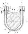
- FIG. 1 shows a cross-section through a peristaltic pump 1 of the rotating type according to the invention.
- Pump 1 comprises: a pump housing 2; a pressing surface 3 present in this pump housing 2 and having the general form of a half-cylinder extending through 180° and having a central axis 5; and an elastically deformable hose 4 which has a medium inlet 6 and a medium outlet 7; a rotor 8 with two pressing cams 9, 10 which are placed diametrically to each other, i.e.
- the indrawn medium is indicated with an arrow 13.
- the medium discharged under pressure is indicated with an arrow 14.
- Pump housing 2 comprises a cavity 15 wholly filled with filling medium 16, in this case a hydraulic oil.
- Cavity 15 is hermetically sealed for this purpose by means of provisions to be described hereinbelow.
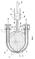
- FIG. 2 shows a pump 21 which differs in one respect from pump 1 according to figure 1, i.e. pump housing 22 has a connection 24 to which connects a conduit 25 which connects in turn to a cavity 28 which is bounded by a cylinder 26 and a piston 27 which is reciprocally displaceable as according to an arrow 30 in sealing manner by means of a sealing ring 29.
- pump housing 22 has a connection 24 to which connects a conduit 25 which connects in turn to a cavity 28 which is bounded by a cylinder 26 and a piston 27 which is reciprocally displaceable as according to an arrow 30 in sealing manner by means of a sealing ring 29.
- the hydraulic oil 26 is incompressible, a displacement of the piston to the left, so with a reduction in the volume of space 28, will exert a pressure on hose 4 such that this will tend to contract and begin to decrease in volume.
- a displacement of piston 27 to the right will increase the volume of space 28, whereby hose 4 will tend to expand. In the description introduction has
- Hose 4 is mounted in hermetically sealing manner relative to the pump housing on the side of both medium inlet 6 and medium outlet 7 of this hose.
- hermetic seal relates only to a practical example and that many other structures can be applied.
Landscapes
- Engineering & Computer Science (AREA)
- Mechanical Engineering (AREA)
- General Engineering & Computer Science (AREA)
- Reciprocating Pumps (AREA)
Applications Claiming Priority (1)
| Application Number | Priority Date | Filing Date | Title |
|---|---|---|---|
| NL2000167A NL2000167C2 (nl) | 2006-07-28 | 2006-07-28 | Peristaltische pomp. |
Publications (1)
| Publication Number | Publication Date |
|---|---|
| EP1884663A1 true EP1884663A1 (fr) | 2008-02-06 |
Family
ID=37888150
Family Applications (1)
| Application Number | Title | Priority Date | Filing Date |
|---|---|---|---|
| EP07112809A Withdrawn EP1884663A1 (fr) | 2006-07-28 | 2007-07-19 | Pompe péristaltique |
Country Status (5)
| Country | Link |
|---|---|
| US (1) | US20080025854A1 (fr) |
| EP (1) | EP1884663A1 (fr) |
| JP (1) | JP2008032017A (fr) |
| NL (1) | NL2000167C2 (fr) |
| ZA (1) | ZA200706199B (fr) |
Cited By (3)
| Publication number | Priority date | Publication date | Assignee | Title |
|---|---|---|---|---|
| CN113586407A (zh) * | 2021-09-16 | 2021-11-02 | 布莱迪(杭州)科学仪器有限公司 | 一种可独立控制的双通道集成蠕动泵 |
| DE102020131083A1 (de) | 2020-11-24 | 2022-05-25 | ventUP GmbH | Schlauch-Pumpe |
| DK181469B1 (en) * | 2021-08-23 | 2024-02-20 | Lsm Pumper Aps | Linear peristaltic pump |
Families Citing this family (10)
| Publication number | Priority date | Publication date | Assignee | Title |
|---|---|---|---|---|
| GB2495937A (en) * | 2011-10-25 | 2013-05-01 | Watson Marlow Ltd | Peristaltic pump head with auxiliary leakage chamber |
| GB2495935A (en) | 2011-10-25 | 2013-05-01 | Watson Marlow Ltd | Peristaltic pump with tube end fitting |
| CN102513020B (zh) * | 2011-12-02 | 2014-04-02 | 上海科勒电子科技有限公司 | 气液混合的液体供送装置 |
| JP2014010078A (ja) * | 2012-06-29 | 2014-01-20 | Jgc Corp | 固液混合体の移送方法及び固液混合体の移送装置 |
| DE102013106170A1 (de) * | 2013-06-13 | 2014-12-31 | Emitec Gesellschaft Für Emissionstechnologie Mbh | Pumpe zur Förderung einer Flüssigkeit |
| GB2521226A (en) * | 2013-12-16 | 2015-06-17 | Watson Marlow Bredel B V | An end fitting for a tube housed by a cavity and a method of installing a tube in a cavity |
| DE102017104395A1 (de) | 2017-03-02 | 2018-09-06 | Qonqave Gmbh | Pumpenvorrichtung zu einer Förderung zumindest eines Fördermittels |
| CN107503923A (zh) * | 2017-09-22 | 2017-12-22 | 保定准择恒流泵制造有限公司 | 蠕动泵头及蠕动泵 |
| CN113062852B (zh) * | 2021-05-02 | 2024-03-29 | 石河子大学 | 一种可调节挤压辊式软管泵 |
| CN115628206B (zh) * | 2022-09-27 | 2023-07-25 | 深圳华星恒泰泵阀有限公司 | 一种便于管道限位的多组连接型蠕动泵 |
Citations (5)
| Publication number | Priority date | Publication date | Assignee | Title |
|---|---|---|---|---|
| GB713239A (en) * | 1952-08-20 | 1954-08-04 | Ames Crosta Mills & Company Lt | Improvements in and relating to flexible tube pumps |
| DE3703124A1 (de) * | 1987-02-03 | 1988-08-11 | Manfred Streicher | Schlauchpumpe |
| WO1991016542A1 (fr) * | 1990-04-12 | 1991-10-31 | Bredel Exploitatie B.V. | Pompe peristaltique comportant des elements de pression retractables |
| DE4303319A1 (de) * | 1993-02-05 | 1994-08-11 | Putzmeister Maschf | Vakuum-Pumpeinrichtung |
| US6171082B1 (en) * | 1997-01-22 | 2001-01-09 | Medtronic, Inc. | Peristaltic pumping mechanism |
Family Cites Families (12)
| Publication number | Priority date | Publication date | Assignee | Title |
|---|---|---|---|---|
| US2428619A (en) * | 1944-11-06 | 1947-10-07 | Douglas Norvel | Rotary pump or the like |
| US3103178A (en) * | 1961-08-11 | 1963-09-10 | Ronald E Thompson | High-capacity pump of tube-compression type |
| US4482347A (en) * | 1982-08-12 | 1984-11-13 | American Hospital Supply Corporation | Peristaltic fluid-pumping apparatus |
| DE3320091A1 (de) * | 1983-06-03 | 1984-12-06 | Streicher, Irmgard, 7141 Beilstein | Schlauchpumpe |
| US4522571A (en) * | 1984-03-05 | 1985-06-11 | Little Robert K | Peristaltic pump |
| US4909710A (en) * | 1989-10-23 | 1990-03-20 | Fisher Scientific Company | Linear peristaltic pump |
| US5217355A (en) * | 1991-08-05 | 1993-06-08 | Imed Corporation | Two-cycle peristaltic pump with occlusion detector |
| DE9205733U1 (de) * | 1992-04-29 | 1993-09-02 | Magnus Gmbh, 42859 Remscheid | Schlauchpumpe |
| DE4214917A1 (de) * | 1992-05-11 | 1993-11-18 | Allweiler Ag | Schlauchpumpe |
| WO1994004257A1 (fr) * | 1992-08-11 | 1994-03-03 | American Cyanamid Company | Appareil pour combiner des liquides |
| GB9815394D0 (en) * | 1998-07-15 | 1998-09-16 | Bredel Hose Pumps B V | Peristalic pumps |
| US20010016706A1 (en) * | 1999-08-31 | 2001-08-23 | Kurt D. Leukanech | Peristaltic pump |
-
2006
- 2006-07-28 NL NL2000167A patent/NL2000167C2/nl not_active IP Right Cessation
-
2007
- 2007-07-19 EP EP07112809A patent/EP1884663A1/fr not_active Withdrawn
- 2007-07-26 ZA ZA200706199A patent/ZA200706199B/xx unknown
- 2007-07-27 US US11/881,828 patent/US20080025854A1/en not_active Abandoned
- 2007-07-30 JP JP2007197608A patent/JP2008032017A/ja active Pending
Patent Citations (5)
| Publication number | Priority date | Publication date | Assignee | Title |
|---|---|---|---|---|
| GB713239A (en) * | 1952-08-20 | 1954-08-04 | Ames Crosta Mills & Company Lt | Improvements in and relating to flexible tube pumps |
| DE3703124A1 (de) * | 1987-02-03 | 1988-08-11 | Manfred Streicher | Schlauchpumpe |
| WO1991016542A1 (fr) * | 1990-04-12 | 1991-10-31 | Bredel Exploitatie B.V. | Pompe peristaltique comportant des elements de pression retractables |
| DE4303319A1 (de) * | 1993-02-05 | 1994-08-11 | Putzmeister Maschf | Vakuum-Pumpeinrichtung |
| US6171082B1 (en) * | 1997-01-22 | 2001-01-09 | Medtronic, Inc. | Peristaltic pumping mechanism |
Cited By (4)
| Publication number | Priority date | Publication date | Assignee | Title |
|---|---|---|---|---|
| DE102020131083A1 (de) | 2020-11-24 | 2022-05-25 | ventUP GmbH | Schlauch-Pumpe |
| DK181469B1 (en) * | 2021-08-23 | 2024-02-20 | Lsm Pumper Aps | Linear peristaltic pump |
| CN113586407A (zh) * | 2021-09-16 | 2021-11-02 | 布莱迪(杭州)科学仪器有限公司 | 一种可独立控制的双通道集成蠕动泵 |
| CN113586407B (zh) * | 2021-09-16 | 2023-09-01 | 布莱迪(杭州)科学仪器有限公司 | 一种可独立控制的双通道集成蠕动泵 |
Also Published As
| Publication number | Publication date |
|---|---|
| US20080025854A1 (en) | 2008-01-31 |
| ZA200706199B (en) | 2008-06-25 |
| JP2008032017A (ja) | 2008-02-14 |
| NL2000167C2 (nl) | 2008-01-29 |
Similar Documents
| Publication | Publication Date | Title |
|---|---|---|
| EP1884663A1 (fr) | Pompe péristaltique | |
| US5649809A (en) | Crankshaft and piston rod connection for a double diaphragm pump | |
| JP4068186B2 (ja) | ロータリポンプ | |
| US7785087B2 (en) | Vane cell pump having pistons guided in cylinder for adjustment of the stator | |
| US4749342A (en) | Diaphragm pump with hydraulically driven rolling diaphragm | |
| JP5576941B2 (ja) | ピストンポンプ | |
| US11703044B2 (en) | Diaphragm for a multi-chamber wobble plate pump | |
| WO2005119063B1 (fr) | Machine de pompage a plusieurs cylindres a commande hydraulique | |
| CA2730696C (fr) | Systeme de commande a fluide hydraulique pour une pompe a diaphragme | |
| CN105386966A (zh) | 微型隔膜泵 | |
| US5899671A (en) | Hydraulic driven diaphragm pump with mechanical diaphragm stroke limitation | |
| US20050191189A1 (en) | Oil seal arrangement | |
| GB2126284A (en) | Radial piston pump | |
| AU2008353297B2 (en) | Hydraulically driven machine improvement | |
| EP1947331A1 (fr) | Améliorations de machine conduite hydrauliquement | |
| US5983777A (en) | Method and apparatus for diaphragm pumping with adjustable flow | |
| EP1496256A3 (fr) | Systeme de desactivation pour pompes en tandem | |
| KR20040049422A (ko) | 안티록 브레이크 시스템용 펌프 | |
| JPH0319916B2 (fr) | ||
| CA2217302A1 (fr) | Pompe hydraulique a circuit de recuperation de fluide | |
| KR20130121328A (ko) | 사판식 압축기 | |
| US10589730B2 (en) | Hydraulic unit of a vehicle brake system having an eccentric chamber | |
| GB2137286A (en) | Variable displacement pump | |
| EP1205664B1 (fr) | Pompe à huile | |
| KR0138128Y1 (ko) | 정수기용 가압펌프의 기밀유지장치 |
Legal Events
| Date | Code | Title | Description |
|---|---|---|---|
| PUAI | Public reference made under article 153(3) epc to a published international application that has entered the european phase |
Free format text: ORIGINAL CODE: 0009012 |
|
| AK | Designated contracting states |
Kind code of ref document: A1 Designated state(s): AT BE BG CH CY CZ DE DK EE ES FI FR GB GR HU IE IS IT LI LT LU LV MC MT NL PL PT RO SE SI SK TR |
|
| AX | Request for extension of the european patent |
Extension state: AL BA HR MK YU |
|
| AKX | Designation fees paid | ||
| REG | Reference to a national code |
Ref country code: DE Ref legal event code: 8566 |
|
| STAA | Information on the status of an ep patent application or granted ep patent |
Free format text: STATUS: THE APPLICATION IS DEEMED TO BE WITHDRAWN |
|
| 18D | Application deemed to be withdrawn |
Effective date: 20080807 |