EP1884739A2 - Procédé et dispositif destinés à la détermination de la masse de marchandises au détail ou de poudre sur un dispositif de convoyage - Google Patents
Procédé et dispositif destinés à la détermination de la masse de marchandises au détail ou de poudre sur un dispositif de convoyage Download PDFInfo
- Publication number
- EP1884739A2 EP1884739A2 EP07113029A EP07113029A EP1884739A2 EP 1884739 A2 EP1884739 A2 EP 1884739A2 EP 07113029 A EP07113029 A EP 07113029A EP 07113029 A EP07113029 A EP 07113029A EP 1884739 A2 EP1884739 A2 EP 1884739A2
- Authority
- EP
- European Patent Office
- Prior art keywords
- powder
- conveyor
- piece goods
- camera
- pieces
- Prior art date
- Legal status (The legal status is an assumption and is not a legal conclusion. Google has not performed a legal analysis and makes no representation as to the accuracy of the status listed.)
- Granted
Links
Images



Classifications
-
- G—PHYSICS
- G01—MEASURING; TESTING
- G01G—WEIGHING
- G01G11/00—Apparatus for weighing a continuous stream of material during flow; Conveyor belt weighers
-
- G—PHYSICS
- G01—MEASURING; TESTING
- G01G—WEIGHING
- G01G9/00—Methods of, or apparatus for, the determination of weight, not provided for in groups G01G1/00 - G01G7/00
-
- G—PHYSICS
- G06—COMPUTING OR CALCULATING; COUNTING
- G06T—IMAGE DATA PROCESSING OR GENERATION, IN GENERAL
- G06T7/00—Image analysis
- G06T7/0002—Inspection of images, e.g. flaw detection
- G06T7/0004—Industrial image inspection
Definitions
- the invention relates to a method for determining the mass of a distributed on a conveyor pourable or pourable piece goods, comprising the steps of: distributing individual pieces of the piece goods on the conveyor such that a predominant part thereof does not overlap each other; Conveying the piece goods on the conveyor along a conveying direction; Passing the pieces arranged on the conveyor through a detection area of at least two cameras; Generating continuous images of the pieces in the detection area using the cameras; Generating geometric data of the pieces on the basis of the images in dependence on the position of the pieces on the conveyor; and calculating the mass of the pieces arranged on the conveyor based on the geometrical data thereof depending on the position of the pieces on the conveyor.
- the DE 698 06 579 T2 describes a device in which taken by means of a digital camera images of food on a conveyor belt and the images are used in a computer to calculate the cooling of the food on the basis of the food flowing around the cooling fluid.
- the device comprises a conveyor 1 in the form of a conveyor belt on which the parcel 3 is distributed.
- the individual pieces 3S of the piece goods 3 are distributed on the conveyor belt 1 in such a way that a predominant part of the pieces 3S of the piece goods 3 does not overlap each other.
- the conveyor belt 1 conveys the piece goods along a conveying direction FR at a constant speed.
- the conveyor belt 1 is driven by a conveyor drive 1A, which is controlled by a data processing system 13.
- two cameras 5 are arranged, each having a detection area 5E, wherein the detection areas 5E of the cameras 5 overlap on the conveyor belt 1.
- Each piece 3S of the piece goods 3 is thus photographed from two directions, and the pictures of the pieces 3S are merged in the data processing unit 13.
- the data processing system 13 interpolates from the image data of the cameras 5 a volume of the pieces 3S of the piece goods 3, for example, by the pieces 3S of the piece goods 3 are approximated by ellipsoids.
- the thus generated volume information about the pieces 3S is multiplied by the density of the piece 3, thereby giving the mass of the individual pieces 3S.
- the data processing system 13 Since the data processing system 13 is informed by arranged on the conveyor belt 1 pulse encoder, the actual feed of the conveyor belt 1, are in the data processing system 13 before data indicating which mass of Guts at which distance from a discharge edge 1AK of the conveyor belt 1 is arranged.
- a disadvantage of the method according to FIG. 1 is that, due to the volume interpolation, this is very compute-intensive and expensive.
- a disadvantage of the device according to FIG. 1 is that it is complicated and expensive due to the at least two cameras and due to the high computing power required by the data processing system 13.
- a disadvantage of the method and the device is that they are only suitable for general cargo.
- the object of the present invention is therefore to simplify the device according to FIG. 1 and to reduce the processing time in the data processing system.
- Another object of the present invention is to overcome the limitation on piece goods, and to provide an expansion to powder.
- a predetermined mass of the piece is preferably distributed on the conveyor and passed through the detection range of the camera, and the projection surface dimensions of pieces of this piece are added to a total projection area, so that the average basis weight as a quotient of the predetermined mass and the total projection area dimension of the piece good.
- a projection area centroid is determined by the projection area of each piece of the piece good.
- predetermined heights of the powder are distributed on the conveyor and passed through the detection range of the camera in order to associate an intensity of the light source with each layer height.
- the piece goods or the powder is scattered onto the conveyor in a continuous stream of material, and a conveying speed of the conveyor is set such that the individual pieces of the piece do not overlap or a predetermined maximum height of the powder is not exceeded.
- the piece goods or the powder are guided in step c) at a continuous speed through the detection area of the at least one camera.
- line images are generated by the camera, covering a width of the conveyor.
- step e) the images of the piece goods on the conveyor in a data processing system can be joined to one another on the basis of mutual overlapping regions.
- the triggering of the camera is triggered by a signal that reproduces the feed of the conveyor.
- defective pieces of the piece goods or defective powder portions are sorted out with the aid of a sorting device, which is arranged in the conveying direction before or after the at least one camera.
- step e determines the mass of piece goods, preferably pieces of the piece goods with a projection area dimension that is smaller than a predefined minimum size are not taken into account in step e).
- the pieces can be illuminated in step d) by light sources arranged above and / or below the conveyor.
- the at least one camera in step d) preferably produces images of the pieces arranged on the conveyor, which show the vertical projection surface of the piece goods on the conveyor.
- a device for determining the mass of a pourable or pourable piece goods or powder with a conveyor on which the piece goods or powder is distributed, at least one camera, which is directed to the conveyor and images of the on the Produced conveying device arranged piece goods or powder, as well as a data processing system that receives and evaluates the images generated by the camera to determine the mass of the piece goods or powder, the device is adapted to the mass of the piece goods or powder by a method according to one of Claims 1 to 14 to determine.
- a device for the metered delivery of a pourable or pourable piece goods or powder with a conveyor on which the good or powder is distributed, at least one camera, which is directed to the conveyor and images of on the device produces arranged piece goods or powder, as well as a data processing system that receives and evaluates the images generated by the camera to dissipate a desired mass of the piece or powder from the conveyor, wherein the device is arranged, the mass of pieces of the piece goods and their To determine position or mass of the powder and its mass distribution on the conveyor by a method according to one of claims 1 to 14.
- the conveyor is a conveyor belt or a vibrating trough.
- the conveyor belt or the vibrating channel is formed by a transparent material, and a light source disposed underneath to guide a light from the light source through the powder or to illuminate the pieces of the piece goods.
- an optical axis of the at least one camera is arranged perpendicular to the conveying direction.
- the conveyor comprises a scraper, which is arranged in the conveying direction after a discharge edge of the conveyor.
- the light source can be an IR, UV or colored light source.
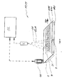
- a conveyor 1 in Fig. 2 in the form of a conveyor belt is driven by a conveyor drive 1A, which is controlled by a data processing system 13.
- the data processing system 13 transmits a desired target speed to the conveyor drive 1A, and receives from the conveyor belt 1 associated transmitters the actual feed of the conveyor belt 1.
- the data processing system 13 can therefore control the conveyor drive 1A so that the conveyor belt 1 has a desired conveying speed.
- pieces 3S of a piece goods 3 are distributed, with the pieces 3S of the piece goods 3 being distributed on the conveyor belt 1 such that a predominant part thereof does not overlap each other.
- the pieces 3S of the piece goods are conveyed on the conveyor belt 1 along a conveying direction FR, and discharged from the conveyor belt 1 at a discharge edge 1AK of the conveyor belt 1.
- the conveyor belt 1 is compared with the discharge edge 1 AAK scraper 21 assigned stripping the return belt of the conveyor belt 1 adhering to the conveyor belt 3 1.
- the conveyor belt 1 is transparent, formed for example from a transparent or white plastic material, and between a delivery side 1FS and a return side 1RS of the conveyor belt 1, a light source 9 is arranged so that light rays from the light source 9 through the delivery side 1FS of the conveyor belt 1.
- the light source 9 may consist of one or more lamps, the light source 9 preferably having a constant illuminance along its longitudinal axis. Reflectors are preferably associated with the light source 9 in such a way that light beams from the light source 9 run for the most part perpendicular to the plane of the conveying side 1FS of the conveyor belt 1.
- the pieces 3S of the piece goods 3 are illuminated from below.
- Illumination of the pieces 3S of the piece goods 3 can alternatively be achieved by arranging one or more lamps above the delivery side 1FS of the conveyor belt 1.
- a camera 5 is arranged, whose optical axis 50A is perpendicular to the plane of the conveying side 1FS of the conveyor belt 1.
- a detection area 5E of the camera 5 is set so as to cover the area of the conveying side 1FS of the conveyor belt 1 which is illuminated by the light source 9.
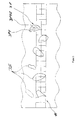
- the camera 5 creates line images 11, as shown in FIG. 3, of the pieces 3S on the conveyor belt 1.
- the camera 5 is arranged above the conveying side 1FS of the conveyor belt 1 and the pieces 3S of the piece goods 3 are illuminated from below, the camera 5 creates images of the pieces 3 S of the piece goods 3, which has a projection surface 3PF of each piece 3 S on the delivery side 1FS of the conveyor belt 1 show. Characterized in that the pieces 3S of the piece goods 3 are illuminated from below, the images produced by the camera 5 show the vertical projection surface of the pieces 3 S on the delivery side 1FS.
- the triggering of the camera 5 is controlled by the data processing system 13.
- the data processing equipment obtains the actual feed of the conveyor belt 1 from pulse generators, not shown, and uses this data to trigger the triggering of the camera 5 so that successive images without an overlapping area can be joined together to form a "continuous film" to receive 3 S arranged on the conveyor belt 1 pieces.
- the successive images of the camera 5 are joined together, and processed as follows.
- the data processing system 13 assigns to each blackened area on one of the images of the camera 5, that is, a projection surface 3PF of a piece 3S, a centroid 3PFS determined by a simple mathematical method is, for example, by a tangent method. Further, the data processing equipment 13 determines the amount of each projection surface 3PF of a piece 3S.
- the camera 5 Since the camera 5 is arranged at a fixed distance from the discharge edge 1AK of the conveyor belt 1 and the data processing system 13, the actual feed of the conveyor belt 1 is known by the pulse generator, are present in the data processing system 13 data about each piece 3S, the distance of the projection center of gravity Specify 3PFS from the discharge edge 1AK and the projection surface dimension of the respective item 3 S.
- the pieces 3S of the piece goods are assigned a mass in the data processing system 13 by multiplying the projection area dimension of each piece 3S by an average basis weight which is determined as follows.
- a predetermined mass of the piece goods 3 is distributed on the conveyor belt 1, and passed through the detection area 5E of the camera 5.
- the projection surface dimension for each piece 3 S of the piece goods 3 is determined, and the individual projection surface dimensions are added to a total projection area measurement.
- the average basis weight results from the quotient of the predetermined mass to the total total projection area dimension of the piece good 3.
- the average basis weight determined in this way thus indicates how much mass is associated on average with a certain projection surface measure. Characterized in that on the conveyor belt 1, a large number of pieces 3 S is arranged, and whose mass does not differ significantly from one another, errors in the mass determination of individual pieces 3 S compensate, whereby the mass of, for example, on a meter conveyor belt 1 arranged pieces 3 S with a Error can be determined which is less than 10%.
- the average basis weight determined in this way is characteristic of the particular product and its production process. Therefore, the average basis weight for each type of cargo 3 must be determined individually.
- the average surface masses of a piece goods 3 may differ if this was produced at different times from a starting product.
- the piece goods 3 are pieces of vegetables which were once made from vegetables before maturity and once from vegetables after maturity, the average basis weight may differ from one another, since the pieces of vegetables have a different water content.
- the average basis weight may be dependent on the type of pieces 3S of the piece goods 3. For example, once apples are divided into quarters and sliced once, their average basis weight will be different.
- a quantity of the piece goods 3, the mass of which is to be determined, is distributed on the conveyor belt 1.
- the pieces 3S of the piece goods 3 are passed through the detection area 5E of the camera 5, and the data processing equipment 13 determines the projection surface mass of the individual pieces 3S of the piece goods and adds them to a total projection area dimension.
- the arrangement described with reference to FIG. 2 can also be used as a dosing and dispensing device 19 for parcel 3.
- the pieces 3S of the piece goods 3 are distributed on the conveyor belt 1, and guided by the detection area 5E of the camera 5.
- the projection surface dimension and the projection area center of gravity 3PFS are determined for each piece 3S of the piece goods 3.
- the data processing system 13 begins to sum up the mass of the individual pieces 3S of the piece goods 3, starting from the discharge edge 1AK counter to the conveying direction FR, until the desired mass has been reached. In this way, the data processing system 13 receives a conveying length which has to be conveyed away from the conveyor belt 1 in order to deliver the mass of the piece goods 3 required by the operator.
- the data processing system 13 sends a corresponding signal to the conveyor drive 1A, which then abrindt the conveyor belt 1 by the calculated conveying length, whereby the operator receives the requested mass of the piece goods 3.
- the data processing system 13 preferably compares the desired value of the feed with the actual value of the feed, which is transmitted by the pulse generators, and optionally carries out a correction.
- the mass requested by the operator may be larger or smaller than the mass arranged between the discharge edge 1AK and the light source 9 on the delivery side 1FS of the conveyor belt 1. If the mass of the piece goods 3 requested by the operator is smaller than the mass lying in this area, then the data processing system 13 can directly calculate and convey away the conveying length to be removed. If the mass requested by the operator is greater than the mass of the piece goods 3 lying in this area, the data processing system 13 calculates the mass of the pieces 3S of the piece goods guided through the detection area 5E of the camera 5 and advances the conveyor belt 1 until the requested mass is conveyed away from the conveyor belt 1. Due to the simplicity of the Method, the conveyor belt 1 can be operated even in the latter case with a high conveying speed.
- the discharge edge 1AK of the conveyor belt 1 can be withdrawn a corresponding length (withdrawal edge).
- a sorting device known in the art can be arranged to sort out faulty piece goods 3 from the conveyor belt 1.
- the accuracy of the above-described method for determining the mass of parcel 3 is limited by the resolution of the camera 5, since a piece 3S of the parcel 3 having a size smaller than the resolution of the camera is not detected.
- the camera 5 in the embodiment of FIG. 2 has 1024 pixels in the present case and thus covers a width of the conveyor belt 1 of 250 mm, so that one pixel corresponds to approximately 0.25 mm. Therefore, pieces 3S having a projection area smaller than 0.06 mm 2 are not detected by the camera 5 and the data processing equipment 13.
- the data processing system 13 may additionally be programmed so that it generally does not consider pieces 3S having a projection area dimension below a predetermined limit. For example, the data processing system 13 may be arranged to disregard pieces 3S having a screen size of less than 1 mm 2 .
- a dosing and dispensing device 19 is used, for example, in the food industry to add a predetermined mass of frozen minced meat to a ready-made pizza, the purchaser of the finished pizza receives the predetermined mass of minced meat and, in addition, the pieces of minced meat having an area less than one mm 2 .
- the conveying speed of the conveyor belt 1 is preferably constant. If the arrangement of FIG. 2 is used as a metering and dispensing device, the conveyor belt 1 is initially accelerated at the beginning of dispensing of the piece goods 3 and braked towards the end of dispensing. The conveyor belt 1 should in any case be accelerated so that the pieces 3S of the piece goods. 3 do not slip on the conveyor belt 1, since then present in the data processing system 13 projection area centers 3PFS no longer coincide with the actual.
- the conveyor belt 1 can therefore depressions, for example, depressions, have to prevent slipping of the piece goods. Alternatively or additionally, the conveyor belt 1 may have a non-slip surface.
- the piece goods 3 is preferably distributed in a waterfall method on the conveyor belt 1. This can be achieved, for example, by delivering the article 3 in a continuous stream of material from a feed belt to the conveyor belt 1, wherein the ratio of the conveying speeds is set such that the individual pieces 3S of the piece goods 3 on the conveyor belt 1 for the most part do not overlap.
- the exemplary embodiment described above with reference to FIGS. 2 and 3 is restricted to piece goods having a minimum size which is greater than the resolution of the camera 5.
- the conveyor belt 1 of FIG. 4 is therefore covered with a powder 7 in contrast to that of FIG.
- the powder 7 has a grain size which is smaller than the resolution of the camera 5, so that the grains of the powder presently have a diameter which is smaller than 0.25 mm.
- the powder is largely homogeneous in terms of its particle size distribution, its color, its gloss, its transparency and moisture.
- powder 7 flour sugar or starch may be mentioned.
- the greyscale values in the line image 11A of FIG. 5A thus correspond to a height 7H of the powder 7 on the conveyor belt 1, so that the individual gray scale values of the pixels can be combined to form a layer height profile 7S of the powder 7 on the conveyor belt 1 shown in FIG. 5B is shown.
- the conversion of the grayscale values in the line image 11 of FIG. 5A into a layer height 7H of the powder 7 on the conveyor belt is effected by means of a layer height-intensity relation, which is determined for each powder 7 as follows, for example.
- a predetermined layer height of the powder 7 is applied by means of a doctor blade and / or brush, and the greyscale value corresponding to this height 7H of the powder 7 is determined by means of the data processing system 13 and the camera 5. This process is repeated for at least 5, preferably more than 10, and more preferably more than 15 heights 7H of the powder 7.
- an allocation table is created, which assigns each of, for example, 10 measured heights 7H of the powder 7 on the conveyor belt 1 to a greyscale value in the line image 11 of the camera 5.
- the heights to be measured 7H of the powder 7 on the conveyor belt 1 for the preparation of the allocation table, it should be noted that there is an individual maximum height 7H for each powder 7, above the height 7H of the powder 7 on the conveyor belt 1 the same grayscale value is assigned, namely the maximum grayscale value.
- the 10 layer heights to be measured should therefore be chosen so that they are evenly distributed between 0 mm and the maximum height 7H of the powder 7.
- a squeegee should be arranged, which is set to this maximum height of the powder 7, in order to ensure that the powder 7 is not guided with a greater height 7H into the detection area 5E of the camera that each height 7H of the powder 7 in the detection area 5E of the camera 5, a corresponding gray level value can be assigned.
- the values of the allocation table are subsequently interpolated by means of a known interpolation method, resulting in a continuous function, the layer height-intensity relation.
- the layer height-intensity relation depends on a large number of parameters, for example the grain size, the grain size distribution, the color, the gloss, the transparency and the humidity of the powder 7. Due to this large number of parameters, the layer height-intensity relationship should 7 are determined individually for each powder.
- the layer height-intensity relationship is generated as a continuous function, resulting in low error tolerances in the determination of the mass. If larger error tolerances are allowed, the use of the allocation table described above may be sufficient, but this should have a number of measured heights 7H adapted to the error tolerances and an optimum distribution of the heights 7H.
- the powder 7 is distributed, wherein the layer height-intensity relation of the powder 7, as described above, has been determined.
- a doctor blade is arranged, which is set to a maximum height for the powder 7.
- the powder 7 arranged on the conveyor belt 1 is guided through the detection area 5E of the camera 5, and the associated greyscale values are determined by the data processing system 13. With the aid of the layer height-intensity relation, this results in a layer height profile 7S of the powder 7 on the conveyor belt 1, as illustrated, for example, in FIG. 5b.
- the layer height profile can be converted into a volume profile of the powder 7 on the conveyor belt 1.
- the determination of the mass of a predetermined amount of a powder 7 can thus be carried out in a simple manner with the arrangement according to FIG. 4 by distributing the powder 7 on the conveyor belt 1 and passing it through the detection area 5E of the camera 5.
- the balance 17 described with reference to FIG. 4 is thus identical to the balance 17 described with reference to FIG. 2, except that the calculation of the mass of the powder by means of a volume profile compared to the calculation of the mass of pieces 3S by means of a Projections vomineses done.
- the arrangement described with reference to FIG. 4 can also be used as a metering and dispensing device 19.
- the mass distribution of the powder 7 on the conveyor belt 1 is present.
- the data processing system 13 adds the mass of the powder 7 resting on the conveyor belt 1, starting from the discharge edge 1AK of the conveyor belt 1, counter to the conveying direction FR, until the mass required by the operator arrives is.
- a conveying length of the conveyor belt 1 to be conveyed results in the data processing system 13, and the data processing system 13 controls the conveyor drive 1A such that this conveying length is conveyed away from the conveyor belt 1 to provide the operator 1 with the desired mass of the powder 7 , wherein the actual value of the feed is preferably compared with the target value of the feed in the data processing system 13 and corrected if necessary.
- the metering and dispensing device described with reference to FIG. 4 can thus be operated exactly like the metering and dispensing device described with reference to FIG. 2, and differs only in that the mass of the powder 7 by means of a volume profile in contrast to a projection surface dimension in a piece goods 3 is determined.
- the embodiment described with reference to FIGS. 4 and 5 requires a transmission of the light emitted by the light source 9 through the powder 7.
- the conveyor belt 1 and the lighting 9 must therefore meet higher requirements compared with the embodiment described with reference to FIGS. 2 and 3.
- the conveyor belt 1, of the embodiment described with reference to FIGS. 4 and 5 has to meet higher requirements with regard to the homogeneity and constancy of the light transmission than the conveyor belt 1 of the embodiment described with reference to FIGS. 2 and 3.
- the light source 9 in FIG. 4 must meet higher requirements with regard to the homogeneity and the constancy of the illuminance than those described with reference to FIG. 2.
- the light source 9 may be a normal white light source in the embodiments described above.
- the light source 9 may be an IR, UV or colored light source. This is particularly advantageous in the transmission of the powder 7, since with other wavelengths may deeper penetration of the powder 7 can be achieved, whereby the maximum height of the arranged on the conveyor belt 1 powder 7 increases, so that a larger throughput of powder 7 reached can be.
- a camera 5 can be used with a gamma correction, so that even in the camera 5 dark image contents are displayed disproportionately brighter (different characteristics). Alternatively, this can be done by a digital image processing in the data processing system 13.
- the methods of determining the mass of the piece goods 3 and the powder 7 are preferably carried out in the data processing system 13 by a software that is programmed accordingly. Since the arrangements of FIGS. 2 and 4 are constructed from the same components and differ only in the manner of calculating the mass of the piece goods 3 and of the powder 7, it is sufficient to change the software in order to use the arrangement of FIG. 2 to determine the mass of powder 7 or with the arrangement of Fig. 4, the mass of cargo 3.
Landscapes
- Physics & Mathematics (AREA)
- General Physics & Mathematics (AREA)
- Engineering & Computer Science (AREA)
- Quality & Reliability (AREA)
- Computer Vision & Pattern Recognition (AREA)
- Theoretical Computer Science (AREA)
- Length Measuring Devices By Optical Means (AREA)
- Sorting Of Articles (AREA)
- Control Of Conveyors (AREA)
Priority Applications (1)
| Application Number | Priority Date | Filing Date | Title |
|---|---|---|---|
| PL07113029T PL1884739T3 (pl) | 2006-07-31 | 2007-07-24 | Sposób i urządzenie do określania masy ładunku drobnicowego lub proszku na urządzeniu przenośnikowym |
Applications Claiming Priority (1)
| Application Number | Priority Date | Filing Date | Title |
|---|---|---|---|
| DE102006035266A DE102006035266B4 (de) | 2006-07-31 | 2006-07-31 | Verfahren und Vorrichtung zur Bestimmung der Masse von Stückgut oder Pulver auf einer Fördereinrichtung |
Publications (3)
| Publication Number | Publication Date |
|---|---|
| EP1884739A2 true EP1884739A2 (fr) | 2008-02-06 |
| EP1884739A3 EP1884739A3 (fr) | 2008-03-26 |
| EP1884739B1 EP1884739B1 (fr) | 2015-03-11 |
Family
ID=38645658
Family Applications (1)
| Application Number | Title | Priority Date | Filing Date |
|---|---|---|---|
| EP07113029.8A Active EP1884739B1 (fr) | 2006-07-31 | 2007-07-24 | Procédé et dispositif destinés à la détermination de la masse de marchandises au détail ou de poudre sur un dispositif de convoyage |
Country Status (3)
| Country | Link |
|---|---|
| EP (1) | EP1884739B1 (fr) |
| DE (1) | DE102006035266B4 (fr) |
| PL (1) | PL1884739T3 (fr) |
Cited By (5)
| Publication number | Priority date | Publication date | Assignee | Title |
|---|---|---|---|---|
| EP1952693A1 (fr) | 2007-01-31 | 2008-08-06 | Dr. August Oetker Nahrungsmittel KG | Procédé et dispositif de décoration ou de garniture d'une section horizontale d'un produit de boulangerie plat |
| CN103308127A (zh) * | 2013-06-05 | 2013-09-18 | 中国矿业大学(北京) | 基于图像技术的皮带称重方法 |
| CN107702755A (zh) * | 2017-11-27 | 2018-02-16 | 宁夏广天夏电子科技有限公司 | 皮带输送机流量检测装置及检测方法 |
| CN116295742A (zh) * | 2023-03-22 | 2023-06-23 | 哈尔滨工程大学 | 果蔬质量预测方法、装置与设备 |
| CN117485808A (zh) * | 2023-11-02 | 2024-02-02 | 贵州惠水西南水泥有限公司 | 一种水泥检测工艺 |
Families Citing this family (2)
| Publication number | Priority date | Publication date | Assignee | Title |
|---|---|---|---|---|
| US10776972B2 (en) | 2018-04-25 | 2020-09-15 | Cognex Corporation | Systems and methods for stitching sequential images of an object |
| DE102018129480A1 (de) * | 2018-11-22 | 2020-05-28 | Fresenius Medical Care Deutschland Gmbh | Vorrichtung und Verfahren zum Dosieren von pulverförmigen Stoffen und Verpackung zur Aufnahme von pulverförmigen Stoffen für eine Vorrichtung zum Dosieren von pulverförmigen Stoffen |
Citations (7)
| Publication number | Priority date | Publication date | Assignee | Title |
|---|---|---|---|---|
| JPS56157820A (en) | 1980-05-08 | 1981-12-05 | Fujita Corp | Measuring apparatus of weight of transported matter |
| DD268998A1 (de) | 1984-07-24 | 1989-06-14 | Orgreb Inst Kraftwerke | Radiometrische foerderbandwaage |
| DE4204843A1 (de) | 1991-02-19 | 1992-08-20 | Marel Seattle Inc | Verfahren und vorrichtung zur bestimmung des volumens, der form und des gewichts von fisch oder anderen objekten |
| JP2002005637A (ja) | 2000-06-22 | 2002-01-09 | Sumitomo Metal Mining Co Ltd | 高温状態にある粒状物集合体の体積若しくは重量測定法 |
| DE10136980A1 (de) | 2001-03-14 | 2002-09-19 | Fritsch A Gmbh & Co Kg | Verfahren und Vorrichtung zur Bestimmung der Masse eines Teigbandabschnittes |
| DE69806579T2 (de) | 1997-03-03 | 2003-02-20 | L'air Liquide, S.A. A Directoire Et Conseil De Surveillance Pour L'etude Et L'exploitation Des Procedes Georges Claude | Anlage zur behandlung von nahrungsmitteln |
| US20050241862A1 (en) | 2002-08-16 | 2005-11-03 | Tsinghua University | Equipment for on-line measuring the weight of material |
-
2006
- 2006-07-31 DE DE102006035266A patent/DE102006035266B4/de not_active Expired - Fee Related
-
2007
- 2007-07-24 PL PL07113029T patent/PL1884739T3/pl unknown
- 2007-07-24 EP EP07113029.8A patent/EP1884739B1/fr active Active
Patent Citations (7)
| Publication number | Priority date | Publication date | Assignee | Title |
|---|---|---|---|---|
| JPS56157820A (en) | 1980-05-08 | 1981-12-05 | Fujita Corp | Measuring apparatus of weight of transported matter |
| DD268998A1 (de) | 1984-07-24 | 1989-06-14 | Orgreb Inst Kraftwerke | Radiometrische foerderbandwaage |
| DE4204843A1 (de) | 1991-02-19 | 1992-08-20 | Marel Seattle Inc | Verfahren und vorrichtung zur bestimmung des volumens, der form und des gewichts von fisch oder anderen objekten |
| DE69806579T2 (de) | 1997-03-03 | 2003-02-20 | L'air Liquide, S.A. A Directoire Et Conseil De Surveillance Pour L'etude Et L'exploitation Des Procedes Georges Claude | Anlage zur behandlung von nahrungsmitteln |
| JP2002005637A (ja) | 2000-06-22 | 2002-01-09 | Sumitomo Metal Mining Co Ltd | 高温状態にある粒状物集合体の体積若しくは重量測定法 |
| DE10136980A1 (de) | 2001-03-14 | 2002-09-19 | Fritsch A Gmbh & Co Kg | Verfahren und Vorrichtung zur Bestimmung der Masse eines Teigbandabschnittes |
| US20050241862A1 (en) | 2002-08-16 | 2005-11-03 | Tsinghua University | Equipment for on-line measuring the weight of material |
Cited By (6)
| Publication number | Priority date | Publication date | Assignee | Title |
|---|---|---|---|---|
| EP1952693A1 (fr) | 2007-01-31 | 2008-08-06 | Dr. August Oetker Nahrungsmittel KG | Procédé et dispositif de décoration ou de garniture d'une section horizontale d'un produit de boulangerie plat |
| CN103308127A (zh) * | 2013-06-05 | 2013-09-18 | 中国矿业大学(北京) | 基于图像技术的皮带称重方法 |
| CN103308127B (zh) * | 2013-06-05 | 2015-04-01 | 中国矿业大学(北京) | 基于图像技术的皮带称重方法 |
| CN107702755A (zh) * | 2017-11-27 | 2018-02-16 | 宁夏广天夏电子科技有限公司 | 皮带输送机流量检测装置及检测方法 |
| CN116295742A (zh) * | 2023-03-22 | 2023-06-23 | 哈尔滨工程大学 | 果蔬质量预测方法、装置与设备 |
| CN117485808A (zh) * | 2023-11-02 | 2024-02-02 | 贵州惠水西南水泥有限公司 | 一种水泥检测工艺 |
Also Published As
| Publication number | Publication date |
|---|---|
| PL1884739T3 (pl) | 2015-08-31 |
| DE102006035266A1 (de) | 2008-02-07 |
| EP1884739B1 (fr) | 2015-03-11 |
| EP1884739A3 (fr) | 2008-03-26 |
| DE102006035266B4 (de) | 2008-06-19 |
Similar Documents
| Publication | Publication Date | Title |
|---|---|---|
| EP1884739B1 (fr) | Procédé et dispositif destinés à la détermination de la masse de marchandises au détail ou de poudre sur un dispositif de convoyage | |
| EP0297309B1 (fr) | Procédé et dispositif de mesure et de régulation du débit de poudre dans une installation de revêtement par poudrage par pulvérisation | |
| DE69533238T2 (de) | Verfahren und vorrichtung zum automatischen bewerten von getreidekörnern | |
| EP0179108B1 (fr) | Installation de mesure aux infrarouges pour l'analyse continue de produits moulus | |
| EP2375380B1 (fr) | Procédé et dispositif de mesure d'un paramètre lors du transport d'objets vers un dispositif de traitement | |
| AT398174B (de) | Verfahren und vorrichtung zum trennen von entrindeten holzknüppeln | |
| EP1625367B1 (fr) | Procede et dispositif de pese de produits | |
| EP2315650B1 (fr) | Procédé et dispositif pour obtenir des données de commande pour un dispositif de coupe de produits alimentaires ainsi que pour obtenir de tranches constantes au niveau du poids de produits sur la base de lesdites données de commande | |
| DE19820058B4 (de) | Verfahren zum Zerteilen von Produktlaiben sowie Vorrichtung zu seiner Durchführung | |
| WO1992018864A1 (fr) | Procede et dispositif de mesure nir en ligne de produits alimentaires coulants | |
| DE19604254B4 (de) | Verfahren und Vorrichtung zur Gewinnung gewichtskonstanter Portionen oder Scheiben aus aufgeschnittenen Lebensmittelprodukten | |
| DE102007040301B4 (de) | Verfahren und Vorrichtung zur dynamischen Kontrollwägung | |
| DE102012016332B4 (de) | Verfahren zur Steuerung und/oder Regelung eines Volumenstromes, eines Schüttgutes oder von Schüttgütern, insbesondere von mineralischen Schüttgütern, von Abfallstoffen, von Rohstoffen oder von Materialen bzw. Vorrichtung zur Durchführung des zuvor genannten Verfahrens | |
| EP0466857A1 (fr) | Dispositif, procede et mise en uvre du procede pour la detection d'un flux de production. | |
| DE102016003766B4 (de) | Vereinzelungsvorrichtung | |
| DE112008001838T5 (de) | Prüfvorrichtung und Prüfverfahren, welches durchdringende Strahlung verwendet | |
| EP1925921B1 (fr) | Procédé et dispositif destinés à la détermination de la masse de marchandises au détail sur un dispositif de convoyage | |
| AT523755A2 (de) | Verfahren zum abschnittsweisen Bestimmen der Korngrößenverteilung eines auf ein Förderband aufgegebenen Schüttgutes | |
| DE60315581T2 (de) | Wiege- und Aromatisierungseinrichtung und Verpackungsmaschine | |
| DE69013562T2 (de) | Vorrichtung zur Bildung einer kontinuierlichen Schicht von körnigem und/oder pulverigem Material in einer Paniermaschine. | |
| EP4508398A1 (fr) | Dispositif de dosage et/ou de pesage pour aliments | |
| DE19756367C2 (de) | Fütterungsanlage für die Tierhaltung | |
| EP2047248B1 (fr) | Procédé et dispositif pour déterminer la teneur en graisse de morceaux de viande dans leur ensemble | |
| DE2346967A1 (de) | Vorrichtung zum messen der durchflussmenge eines pulverfoermigen oder koernigen materials | |
| EP3933354B1 (fr) | Surveillance améliorée des balances de combinaison au moyen d'un capteur 3d |
Legal Events
| Date | Code | Title | Description |
|---|---|---|---|
| PUAI | Public reference made under article 153(3) epc to a published international application that has entered the european phase |
Free format text: ORIGINAL CODE: 0009012 |
|
| AK | Designated contracting states |
Kind code of ref document: A2 Designated state(s): AT BE BG CH CY CZ DE DK EE ES FI FR GB GR HU IE IS IT LI LT LU LV MC MT NL PL PT RO SE SI SK TR |
|
| AX | Request for extension of the european patent |
Extension state: AL BA HR MK YU |
|
| PUAL | Search report despatched |
Free format text: ORIGINAL CODE: 0009013 |
|
| AK | Designated contracting states |
Kind code of ref document: A3 Designated state(s): AT BE BG CH CY CZ DE DK EE ES FI FR GB GR HU IE IS IT LI LT LU LV MC MT NL PL PT RO SE SI SK TR |
|
| AX | Request for extension of the european patent |
Extension state: AL BA HR MK YU |
|
| 17P | Request for examination filed |
Effective date: 20080926 |
|
| AKX | Designation fees paid |
Designated state(s): AT BE BG CH CY CZ DE DK EE ES FI FR GB GR HU IE IS IT LI LT LU LV MC MT NL PL PT RO SE SI SK TR |
|
| 17Q | First examination report despatched |
Effective date: 20100625 |
|
| APBK | Appeal reference recorded |
Free format text: ORIGINAL CODE: EPIDOSNREFNE |
|
| APBN | Date of receipt of notice of appeal recorded |
Free format text: ORIGINAL CODE: EPIDOSNNOA2E |
|
| APBR | Date of receipt of statement of grounds of appeal recorded |
Free format text: ORIGINAL CODE: EPIDOSNNOA3E |
|
| APAF | Appeal reference modified |
Free format text: ORIGINAL CODE: EPIDOSCREFNE |
|
| APBT | Appeal procedure closed |
Free format text: ORIGINAL CODE: EPIDOSNNOA9E |
|
| GRAP | Despatch of communication of intention to grant a patent |
Free format text: ORIGINAL CODE: EPIDOSNIGR1 |
|
| INTG | Intention to grant announced |
Effective date: 20140429 |
|
| GRAC | Information related to communication of intention to grant a patent modified |
Free format text: ORIGINAL CODE: EPIDOSCIGR1 |
|
| INTG | Intention to grant announced |
Effective date: 20141114 |
|
| GRAS | Grant fee paid |
Free format text: ORIGINAL CODE: EPIDOSNIGR3 |
|
| GRAA | (expected) grant |
Free format text: ORIGINAL CODE: 0009210 |
|
| AK | Designated contracting states |
Kind code of ref document: B1 Designated state(s): AT BE BG CH CY CZ DE DK EE ES FI FR GB GR HU IE IS IT LI LT LU LV MC MT NL PL PT RO SE SI SK TR |
|
| REG | Reference to a national code |
Ref country code: GB Ref legal event code: FG4D Free format text: NOT ENGLISH |
|
| REG | Reference to a national code |
Ref country code: CH Ref legal event code: EP |
|
| REG | Reference to a national code |
Ref country code: IE Ref legal event code: FG4D Free format text: LANGUAGE OF EP DOCUMENT: GERMAN |
|
| REG | Reference to a national code |
Ref country code: AT Ref legal event code: REF Ref document number: 715585 Country of ref document: AT Kind code of ref document: T Effective date: 20150415 |
|
| REG | Reference to a national code |
Ref country code: DE Ref legal event code: R096 Ref document number: 502007013779 Country of ref document: DE Effective date: 20150423 |
|
| REG | Reference to a national code |
Ref country code: NL Ref legal event code: VDEP Effective date: 20150311 |
|
| REG | Reference to a national code |
Ref country code: NL Ref legal event code: VDEP Effective date: 20150311 |
|
| PG25 | Lapsed in a contracting state [announced via postgrant information from national office to epo] |
Ref country code: FI Free format text: LAPSE BECAUSE OF FAILURE TO SUBMIT A TRANSLATION OF THE DESCRIPTION OR TO PAY THE FEE WITHIN THE PRESCRIBED TIME-LIMIT Effective date: 20150311 Ref country code: ES Free format text: LAPSE BECAUSE OF FAILURE TO SUBMIT A TRANSLATION OF THE DESCRIPTION OR TO PAY THE FEE WITHIN THE PRESCRIBED TIME-LIMIT Effective date: 20150311 Ref country code: SE Free format text: LAPSE BECAUSE OF FAILURE TO SUBMIT A TRANSLATION OF THE DESCRIPTION OR TO PAY THE FEE WITHIN THE PRESCRIBED TIME-LIMIT Effective date: 20150311 Ref country code: LT Free format text: LAPSE BECAUSE OF FAILURE TO SUBMIT A TRANSLATION OF THE DESCRIPTION OR TO PAY THE FEE WITHIN THE PRESCRIBED TIME-LIMIT Effective date: 20150311 |
|
| REG | Reference to a national code |
Ref country code: LT Ref legal event code: MG4D |
|
| PG25 | Lapsed in a contracting state [announced via postgrant information from national office to epo] |
Ref country code: GR Free format text: LAPSE BECAUSE OF FAILURE TO SUBMIT A TRANSLATION OF THE DESCRIPTION OR TO PAY THE FEE WITHIN THE PRESCRIBED TIME-LIMIT Effective date: 20150612 Ref country code: LV Free format text: LAPSE BECAUSE OF FAILURE TO SUBMIT A TRANSLATION OF THE DESCRIPTION OR TO PAY THE FEE WITHIN THE PRESCRIBED TIME-LIMIT Effective date: 20150311 |
|
| REG | Reference to a national code |
Ref country code: PL Ref legal event code: T3 |
|
| PG25 | Lapsed in a contracting state [announced via postgrant information from national office to epo] |
Ref country code: NL Free format text: LAPSE BECAUSE OF FAILURE TO SUBMIT A TRANSLATION OF THE DESCRIPTION OR TO PAY THE FEE WITHIN THE PRESCRIBED TIME-LIMIT Effective date: 20150311 |
|
| PG25 | Lapsed in a contracting state [announced via postgrant information from national office to epo] |
Ref country code: CZ Free format text: LAPSE BECAUSE OF FAILURE TO SUBMIT A TRANSLATION OF THE DESCRIPTION OR TO PAY THE FEE WITHIN THE PRESCRIBED TIME-LIMIT Effective date: 20150311 Ref country code: EE Free format text: LAPSE BECAUSE OF FAILURE TO SUBMIT A TRANSLATION OF THE DESCRIPTION OR TO PAY THE FEE WITHIN THE PRESCRIBED TIME-LIMIT Effective date: 20150311 Ref country code: RO Free format text: LAPSE BECAUSE OF FAILURE TO SUBMIT A TRANSLATION OF THE DESCRIPTION OR TO PAY THE FEE WITHIN THE PRESCRIBED TIME-LIMIT Effective date: 20150311 Ref country code: SK Free format text: LAPSE BECAUSE OF FAILURE TO SUBMIT A TRANSLATION OF THE DESCRIPTION OR TO PAY THE FEE WITHIN THE PRESCRIBED TIME-LIMIT Effective date: 20150311 Ref country code: PT Free format text: LAPSE BECAUSE OF FAILURE TO SUBMIT A TRANSLATION OF THE DESCRIPTION OR TO PAY THE FEE WITHIN THE PRESCRIBED TIME-LIMIT Effective date: 20150713 |
|
| PG25 | Lapsed in a contracting state [announced via postgrant information from national office to epo] |
Ref country code: IS Free format text: LAPSE BECAUSE OF FAILURE TO SUBMIT A TRANSLATION OF THE DESCRIPTION OR TO PAY THE FEE WITHIN THE PRESCRIBED TIME-LIMIT Effective date: 20150711 |
|
| REG | Reference to a national code |
Ref country code: DE Ref legal event code: R097 Ref document number: 502007013779 Country of ref document: DE |
|
| PLBE | No opposition filed within time limit |
Free format text: ORIGINAL CODE: 0009261 |
|
| STAA | Information on the status of an ep patent application or granted ep patent |
Free format text: STATUS: NO OPPOSITION FILED WITHIN TIME LIMIT |
|
| PG25 | Lapsed in a contracting state [announced via postgrant information from national office to epo] |
Ref country code: DK Free format text: LAPSE BECAUSE OF FAILURE TO SUBMIT A TRANSLATION OF THE DESCRIPTION OR TO PAY THE FEE WITHIN THE PRESCRIBED TIME-LIMIT Effective date: 20150311 |
|
| 26N | No opposition filed |
Effective date: 20151214 |
|
| PG25 | Lapsed in a contracting state [announced via postgrant information from national office to epo] |
Ref country code: SI Free format text: LAPSE BECAUSE OF FAILURE TO SUBMIT A TRANSLATION OF THE DESCRIPTION OR TO PAY THE FEE WITHIN THE PRESCRIBED TIME-LIMIT Effective date: 20150311 Ref country code: MC Free format text: LAPSE BECAUSE OF FAILURE TO SUBMIT A TRANSLATION OF THE DESCRIPTION OR TO PAY THE FEE WITHIN THE PRESCRIBED TIME-LIMIT Effective date: 20150311 |
|
| REG | Reference to a national code |
Ref country code: CH Ref legal event code: PL |
|
| PG25 | Lapsed in a contracting state [announced via postgrant information from national office to epo] |
Ref country code: LU Free format text: LAPSE BECAUSE OF FAILURE TO SUBMIT A TRANSLATION OF THE DESCRIPTION OR TO PAY THE FEE WITHIN THE PRESCRIBED TIME-LIMIT Effective date: 20150724 |
|
| REG | Reference to a national code |
Ref country code: IE Ref legal event code: MM4A |
|
| REG | Reference to a national code |
Ref country code: FR Ref legal event code: PLFP Year of fee payment: 10 |
|
| PG25 | Lapsed in a contracting state [announced via postgrant information from national office to epo] |
Ref country code: CH Free format text: LAPSE BECAUSE OF NON-PAYMENT OF DUE FEES Effective date: 20150731 Ref country code: LI Free format text: LAPSE BECAUSE OF NON-PAYMENT OF DUE FEES Effective date: 20150731 |
|
| PG25 | Lapsed in a contracting state [announced via postgrant information from national office to epo] |
Ref country code: IE Free format text: LAPSE BECAUSE OF NON-PAYMENT OF DUE FEES Effective date: 20150724 |
|
| REG | Reference to a national code |
Ref country code: AT Ref legal event code: MM01 Ref document number: 715585 Country of ref document: AT Kind code of ref document: T Effective date: 20150724 |
|
| PG25 | Lapsed in a contracting state [announced via postgrant information from national office to epo] |
Ref country code: AT Free format text: LAPSE BECAUSE OF NON-PAYMENT OF DUE FEES Effective date: 20150724 |
|
| PG25 | Lapsed in a contracting state [announced via postgrant information from national office to epo] |
Ref country code: MT Free format text: LAPSE BECAUSE OF FAILURE TO SUBMIT A TRANSLATION OF THE DESCRIPTION OR TO PAY THE FEE WITHIN THE PRESCRIBED TIME-LIMIT Effective date: 20150311 |
|
| REG | Reference to a national code |
Ref country code: FR Ref legal event code: PLFP Year of fee payment: 11 |
|
| PG25 | Lapsed in a contracting state [announced via postgrant information from national office to epo] |
Ref country code: HU Free format text: LAPSE BECAUSE OF FAILURE TO SUBMIT A TRANSLATION OF THE DESCRIPTION OR TO PAY THE FEE WITHIN THE PRESCRIBED TIME-LIMIT; INVALID AB INITIO Effective date: 20070724 Ref country code: BG Free format text: LAPSE BECAUSE OF FAILURE TO SUBMIT A TRANSLATION OF THE DESCRIPTION OR TO PAY THE FEE WITHIN THE PRESCRIBED TIME-LIMIT Effective date: 20150311 |
|
| PG25 | Lapsed in a contracting state [announced via postgrant information from national office to epo] |
Ref country code: CY Free format text: LAPSE BECAUSE OF FAILURE TO SUBMIT A TRANSLATION OF THE DESCRIPTION OR TO PAY THE FEE WITHIN THE PRESCRIBED TIME-LIMIT Effective date: 20150311 |
|
| PG25 | Lapsed in a contracting state [announced via postgrant information from national office to epo] |
Ref country code: BE Free format text: LAPSE BECAUSE OF NON-PAYMENT OF DUE FEES Effective date: 20150731 |
|
| PG25 | Lapsed in a contracting state [announced via postgrant information from national office to epo] |
Ref country code: TR Free format text: LAPSE BECAUSE OF FAILURE TO SUBMIT A TRANSLATION OF THE DESCRIPTION OR TO PAY THE FEE WITHIN THE PRESCRIBED TIME-LIMIT Effective date: 20150311 |
|
| REG | Reference to a national code |
Ref country code: FR Ref legal event code: PLFP Year of fee payment: 12 |
|
| P01 | Opt-out of the competence of the unified patent court (upc) registered |
Effective date: 20231012 |
|
| REG | Reference to a national code |
Ref country code: DE Ref legal event code: R082 Ref document number: 502007013779 Country of ref document: DE Representative=s name: FLICK GRAF V. STOSCH NIENABER SCHMALZ RECHTSAN, DE Ref country code: DE Ref legal event code: R082 Ref document number: 502007013779 Country of ref document: DE Representative=s name: FLICK GRAF V. STOSCH NIENABER SCHMALZ KOHLRAUS, DE |
|
| PGFP | Annual fee paid to national office [announced via postgrant information from national office to epo] |
Ref country code: PL Payment date: 20250424 Year of fee payment: 19 |
|
| PGFP | Annual fee paid to national office [announced via postgrant information from national office to epo] |
Ref country code: IT Payment date: 20250505 Year of fee payment: 19 |
|
| PGFP | Annual fee paid to national office [announced via postgrant information from national office to epo] |
Ref country code: DE Payment date: 20250509 Year of fee payment: 19 |
|
| PGFP | Annual fee paid to national office [announced via postgrant information from national office to epo] |
Ref country code: GB Payment date: 20250829 Year of fee payment: 19 |
|
| PGFP | Annual fee paid to national office [announced via postgrant information from national office to epo] |
Ref country code: FR Payment date: 20250724 Year of fee payment: 19 |