EP1885153A1 - Flexibles Einrichtungs- und Verbindungsredundanzschema für einen Media Gateway - Google Patents
Flexibles Einrichtungs- und Verbindungsredundanzschema für einen Media Gateway Download PDFInfo
- Publication number
- EP1885153A1 EP1885153A1 EP06300844A EP06300844A EP1885153A1 EP 1885153 A1 EP1885153 A1 EP 1885153A1 EP 06300844 A EP06300844 A EP 06300844A EP 06300844 A EP06300844 A EP 06300844A EP 1885153 A1 EP1885153 A1 EP 1885153A1
- Authority
- EP
- European Patent Office
- Prior art keywords
- interface
- units
- protection
- spare
- link
- Prior art date
- Legal status (The legal status is an assumption and is not a legal conclusion. Google has not performed a legal analysis and makes no representation as to the accuracy of the status listed.)
- Withdrawn
Links
- 238000000034 method Methods 0.000 claims abstract description 4
- 230000005540 biological transmission Effects 0.000 description 5
- 230000008707 rearrangement Effects 0.000 description 4
- 230000001360 synchronised effect Effects 0.000 description 2
- 230000009977 dual effect Effects 0.000 description 1
- 230000000694 effects Effects 0.000 description 1
- 238000005516 engineering process Methods 0.000 description 1
- 238000012423 maintenance Methods 0.000 description 1
- 230000003287 optical effect Effects 0.000 description 1
Images




Classifications
-
- H—ELECTRICITY
- H04—ELECTRIC COMMUNICATION TECHNIQUE
- H04J—MULTIPLEX COMMUNICATION
- H04J3/00—Time-division multiplex systems
- H04J3/02—Details
- H04J3/14—Monitoring arrangements
-
- H—ELECTRICITY
- H04—ELECTRIC COMMUNICATION TECHNIQUE
- H04Q—SELECTING
- H04Q11/00—Selecting arrangements for multiplex systems
- H04Q11/04—Selecting arrangements for multiplex systems for time-division multiplexing
- H04Q11/0421—Circuit arrangements therefor
-
- H—ELECTRICITY
- H04—ELECTRIC COMMUNICATION TECHNIQUE
- H04J—MULTIPLEX COMMUNICATION
- H04J2203/00—Aspects of optical multiplex systems other than those covered by H04J14/05 and H04J14/07
- H04J2203/0001—Provisions for broadband connections in integrated services digital network using frames of the Optical Transport Network [OTN] or using synchronous transfer mode [STM], e.g. SONET, SDH
- H04J2203/0003—Switching fabrics, e.g. transport network, control network
- H04J2203/0012—Switching modules and their interconnections
-
- H—ELECTRICITY
- H04—ELECTRIC COMMUNICATION TECHNIQUE
- H04J—MULTIPLEX COMMUNICATION
- H04J2203/00—Aspects of optical multiplex systems other than those covered by H04J14/05 and H04J14/07
- H04J2203/0001—Provisions for broadband connections in integrated services digital network using frames of the Optical Transport Network [OTN] or using synchronous transfer mode [STM], e.g. SONET, SDH
- H04J2203/0057—Operations, administration and maintenance [OAM]
- H04J2203/006—Fault tolerance and recovery
-
- H—ELECTRICITY
- H04—ELECTRIC COMMUNICATION TECHNIQUE
- H04Q—SELECTING
- H04Q2213/00—Indexing scheme relating to selecting arrangements in general and for multiplex systems
- H04Q2213/13003—Constructional details of switching devices
-
- H—ELECTRICITY
- H04—ELECTRIC COMMUNICATION TECHNIQUE
- H04Q—SELECTING
- H04Q2213/00—Indexing scheme relating to selecting arrangements in general and for multiplex systems
- H04Q2213/13167—Redundant apparatus
-
- H—ELECTRICITY
- H04—ELECTRIC COMMUNICATION TECHNIQUE
- H04Q—SELECTING
- H04Q2213/00—Indexing scheme relating to selecting arrangements in general and for multiplex systems
- H04Q2213/1334—Configuration within the switch
-
- H—ELECTRICITY
- H04—ELECTRIC COMMUNICATION TECHNIQUE
- H04Q—SELECTING
- H04Q2213/00—Indexing scheme relating to selecting arrangements in general and for multiplex systems
- H04Q2213/13341—Connections within the switch
-
- H—ELECTRICITY
- H04—ELECTRIC COMMUNICATION TECHNIQUE
- H04Q—SELECTING
- H04Q2213/00—Indexing scheme relating to selecting arrangements in general and for multiplex systems
- H04Q2213/13367—Hierarchical multiplexing, add-drop multiplexing
Definitions
- the invention relates to a free configurable media gateway, an interface unit, a processing unit and a method for providing a configurable reliability of a gateway function.
- NTN Next Generation Networks
- SONET Synchronous Optical Network
- Ethernet Furthermore stringent system availability and reliability requirements are to be met.
- link redundancy schemes like the linear link protection schemes, e.g. according to ITU-T G.783 and G.8031/Y.1342, as well as equipment redundancy schemes.
- link protection and equipment protection operate fully independent from each other, to ensure that both schemes can switch independently from each other and that, in case one protection scheme is temporarily unavailable, the other scheme is not impacted in its operation.
- equipment protection schemes e.g. 1+1, i.e. one active replaceable equipment item is protected by one standby item, or N+1, i.e. N active replaceable equipment items are protected by one standby item.
- An advanced software redundancy concept for streamed media is e.g. known from the European Patent Application No. 05290650 .
- the above mentioned protection schemes and the arrangement is disclosed in the European Patent Publication No. 1 578 167 .
- the telecommunication switch comprises a plurality of SDH hardware interfaces, each comprising working link connecting means, being designed to be connected to a working SDH link and protection link connecting means, being designed to be connected to a protection SDH link associated to the working SDH link of the SDH hardware interface, wherein to each of said SDH hardware interfaces a SDH termination module is connected, and an equipment protection arrangement, comprising a protection switching hardware module and a spare SDH termination module.
- Each of said SDH hardware interfaces is connected to said equipment protection arrangement by a first SDH connection and a second SDH connection, and the protection SDH link of a first SDH hardware interface of said SDH hardware interfaces is connected to a second SDH hardware interface of said SDH hardware interfaces.
- the second SDH hardware interface is being designed to forward protection SDH signals transmitted by said protection SDH link of said first SDH hardware interface to said equipment protection arrangement using its first SDH connection and said equipment protection arrangement is being designed to switch said protection SDH signals to said spare SDH termination module or the SDH termination module being connected to said first SDH hardware interface according to a protection switching control signal.
- a gateway for interconnecting networks comprising interface units (MIM) and processing units (CIM/PIM), where the interface units (MIM) and the processing units (CIM/PIM) are interconnected by a connection means (MIDPLANE) and where the gateway comprises a spare interface unit and a spare processing unit (S) for redundancy, where the interface units and the processing units comprising control means (Ctrl/OBC) for routing a data path via the connection means providing a variable independent 1 +1 link protection and a variable 1 +1/N+1 independent equipment protection, and in that the interface units comprise additional interfaces for handling link failures.
- the problem is solved inter alia by an interface unit (MIM) for the gateway, that is adapted to provide a variable independent 1 + 1 link protection and a variable 1 +1/N+1 independent equipment protection and in that the interface units comprise additional interfaces for handling link failures.
- MIM interface unit
- the problem is solved inter alia by a processing unit that is adapted to provide a variable independent 1+1 link protection and a variable 1+1/N+1 independent equipment protection.
- a link failure or an equipment failure is configured to protected N+1 by spare interface units and spare processing units (S), by providing a variable independent 1 +1 link protection and a variable 1 + 1/N+ 1 independent equipment protection by integrating an additional spare interface unit or an additional processing module per N operating interface units and N operating processing units and by routing link failures via additional interfaces of the interface units.
- this invention is based on a midplane system architecture principle.
- a interface unit i.e. a card interfacing to a network, i.e. a media interface module provides an interface to a network.
- Another unit is a kind of streaming processor e.g. in the packet or circuit domain.
- This unit is e.g. a packet interface module or circuit interface module.
- the media interface module and the packet or circuit interface module is separated through or better connected via a midplane.
- This midplane provides connectivity between connectivity modules and processing modules, for front end side data paths, and for front and side control path for 1 + 1 equipment protection scheme and line protection scheme and N+1 equipment protection scheme.
- the invention is related to a interface design, which is capable to operate as:
- the invention solves the technical problem to provide a mechanism that enables a high density system architecture and fulfills the requirements of a smooth density increase, i.e. an extensibility going from 1 + 1 equipment protection scheme to N+1 equipment protection scheme.
- the number N shall be driven by the keeping an already existing mid-plane architecture, thus providing the capability to introduce this invention in a running system, onsite and online.
- the invention is interface independent, i.e. the solution is applicable for any transmission type, like SDH/SONET or the aforementioned Ethernet.
- N needs to be flexible and is only driven by #ports per interface module / #active port per x interface modules (any interface module).
- a major improvement is the support of 1 + 1 equipment protection scheme configurations and N+1 equipment protection scheme configurations with and on the same hardware, as well as the support of equipment protection scheme re-arrangement from 1+1 to N+ 1 and vice versa.
- the invention provides the protection for multiple transmission types, i.e. is really transmission type independent. And equipment protection scheme /link protection scheme are really independent.
- midplane design provides usually a high switching capacity and is enhanced with reliability features.
- Recent midplane designs support N+1 protection for several modules without using up any of front user slots and while continuing to support existing modules.
- the invention supports a more flexible system configuration, i.e. the same equipment /hard ware elements could be used for 1 +1 and N+1 configurations.
- 1 + 1 as well as N+ 1
- 1 + 1 enables shortest take over times as standby card can be used as "hot standby”.
- Configuration tasks during switch-over are minimized.
- N+1 enables high density system configurations.
- Multiple redundancy groups consisting of 1 or N active cards and 1 standby card, are controlled through a midplane control bus. Multiple redundancy groups are supported and they can act independent of each other. Without exchanging hardware, re-arrangement between 1 +1 and N+1 configurations is supported.
- Exchangeable interface modules are used to support various interface types, as well as cost efficient dummy elements, e.g. if required for 1 + 1 configurations, thus keeping the costs at a minimum.
- the shown gateway(s) in Fig. 1 comprises media interface modules MIM, and packet interface modules PIM and circuit interface modules CIM.
- a media interface module MIM comprises an equipment protection subsystem EPS and a control component Ctrl.
- the packet interface modules PIM and a circuit interface modules CIM comprises (each) an on board controller OBC and a link protection subsystem LPS.
- the controllers OBC and Ctrl control the equipment protection subsystem EPS and the link protection subsystem LPS on the same module which is shown by dashed arrows.
- a media interface module MIM has external interfaces and internal interfaces. These interfaces that are not connected to the midplane.
- the midplane connects the equipment protection subsystems EPS with the link protection subsystems and the controller components Ctrl with the on board controllers OBC.
- the control paths of the 1 +1 equipment protected device are shown by dashed lines; the data paths are shown by solid lines.
- the internal interfaces are not used.
- each control component Ctrl of a media interface module is connected by three ports.
- the media interface modules MIM and the packet interface modules PIM and circuit interface modules CIM are grouped pair-wise.
- the control paths and the data paths are connected by the midplane as in the 1 + 1 protected gateway.
- the remaining data port is connected via the midplane to spare modules.
- the spare modules are two media interface modules MIM and a packet interface module PIM / circuit interface modules CIM.
- the redundant data path is connected over the internal interface of a media interface module MIM, i.e. in case that a equipment protection is necessary the equipment protection subsystem EPS will establish a data path to the corresponding spare media interface module MIM.
- Active modules are labeled by an "A” where spare modules are labeled by an “S”.
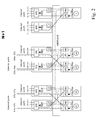
- Fig. 2 shows the nominal operational state.
- the packet interface modules PIM / circuit interface modules CIM are labeled by A1, A2, A3, A4.
- There corresponding external interface ports are labeled by A1w, A2w, A3w, A4w (normal) and by A1s, A2s, A3s, A4s (protection).
- Each equipment protection subsystem has two internal ports labeled by A1iw, A2iw, A3iw, A4iw (normal) and A1is, A2is, A3is, A4is (protection).
- the data path is routed from the normal external interface port Aiw of the media interface module MIM to the associated packet interface modules PIM / circuit interface modules CIM via the mid plane.
- the two spare media interface modules MIM have four internal ports S1w, S2w, S3w, S4w. Thus these modules are identical to any other media interface module MIM.
- Fig. 3 shows a link failure concerning the data path over port Alw.
- This data path is protected by the protection port A1s of the associated pair media interface module MIM A2.
- the data path is routed via the midplane to the corresponding packet interface modules PIM / circuit interface modules CIM. This is shown by bold face data paths.
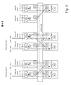
- Fig. 4 shows the active data paths in case of a failure of a media interface module MIM. Then similarly the protection ports as shown in Fig. 3 are chosen. Obviously each pair media interface modules MIM protects the hardware of its pair media interface modules MIM.
- Fig. 5 shows the more complex active data path in case of an equipment failure of a packet interface modules PIM / circuit interface modules CIM.
- the internal ports are wired such that
- Fig. 6 shows a scenario where a link failure and two equipment failures are commonly protected.
- the media interface module MIM A1 , the link to A1w, and the associated packet interface modules PIM / circuit interface modules CIM A1 is broken. Then the two above described protection schemes compensate all failures.
- the data path is routed from the protecting interface port A1s to the second spare media interface module, through the mid plane to the spare packet interface modules PIM /circuit interface modules CIM. This is shown as above by the bold face path.
- the scenarios show an active link protection scheme for a single link failure.
- the link and equipment protection is independent, since only the associated media interface module MIM A1 switchover the link.
Landscapes
- Engineering & Computer Science (AREA)
- Computer Networks & Wireless Communication (AREA)
- Signal Processing (AREA)
- Data Exchanges In Wide-Area Networks (AREA)
Priority Applications (1)
| Application Number | Priority Date | Filing Date | Title |
|---|---|---|---|
| EP06300844A EP1885153A1 (de) | 2006-08-01 | 2006-08-01 | Flexibles Einrichtungs- und Verbindungsredundanzschema für einen Media Gateway |
Applications Claiming Priority (1)
| Application Number | Priority Date | Filing Date | Title |
|---|---|---|---|
| EP06300844A EP1885153A1 (de) | 2006-08-01 | 2006-08-01 | Flexibles Einrichtungs- und Verbindungsredundanzschema für einen Media Gateway |
Publications (1)
| Publication Number | Publication Date |
|---|---|
| EP1885153A1 true EP1885153A1 (de) | 2008-02-06 |
Family
ID=37564255
Family Applications (1)
| Application Number | Title | Priority Date | Filing Date |
|---|---|---|---|
| EP06300844A Withdrawn EP1885153A1 (de) | 2006-08-01 | 2006-08-01 | Flexibles Einrichtungs- und Verbindungsredundanzschema für einen Media Gateway |
Country Status (1)
| Country | Link |
|---|---|
| EP (1) | EP1885153A1 (de) |
Cited By (1)
| Publication number | Priority date | Publication date | Assignee | Title |
|---|---|---|---|---|
| WO2010047629A1 (en) * | 2008-10-23 | 2010-04-29 | Telefonaktiebolaget L M Ericsson (Publ) | Device and system for protection switching |
Citations (3)
| Publication number | Priority date | Publication date | Assignee | Title |
|---|---|---|---|---|
| EP1578167A1 (de) * | 2004-03-09 | 2005-09-21 | Alcatel | Telekommunikationsvermittlungssystem und Betriebsverfahren |
| US20060050631A1 (en) * | 2004-09-03 | 2006-03-09 | Akin Koyuncuoglu | Reconfigurable apparatus providing 1:N and 1:1 equipment redundancy for high speed broadband interfaces with 1‘and 1:N automatic protection switching |
| WO2006040354A1 (en) * | 2004-10-14 | 2006-04-20 | Siemens Aktiengesellschaft | N:1 redundancy scheme for modules with optical interfaces |
-
2006
- 2006-08-01 EP EP06300844A patent/EP1885153A1/de not_active Withdrawn
Patent Citations (3)
| Publication number | Priority date | Publication date | Assignee | Title |
|---|---|---|---|---|
| EP1578167A1 (de) * | 2004-03-09 | 2005-09-21 | Alcatel | Telekommunikationsvermittlungssystem und Betriebsverfahren |
| US20060050631A1 (en) * | 2004-09-03 | 2006-03-09 | Akin Koyuncuoglu | Reconfigurable apparatus providing 1:N and 1:1 equipment redundancy for high speed broadband interfaces with 1‘and 1:N automatic protection switching |
| WO2006040354A1 (en) * | 2004-10-14 | 2006-04-20 | Siemens Aktiengesellschaft | N:1 redundancy scheme for modules with optical interfaces |
Cited By (2)
| Publication number | Priority date | Publication date | Assignee | Title |
|---|---|---|---|---|
| WO2010047629A1 (en) * | 2008-10-23 | 2010-04-29 | Telefonaktiebolaget L M Ericsson (Publ) | Device and system for protection switching |
| US8780695B2 (en) | 2008-10-23 | 2014-07-15 | Telefonaktiebolaget L M Ericsson (Publ) | Device and system for protection switching |
Similar Documents
| Publication | Publication Date | Title |
|---|---|---|
| US8798045B1 (en) | Control plane architecture for switch fabrics | |
| US6253266B1 (en) | Apparatus and method for controlling information flow in a card cage having multiple backplanes | |
| TWI503001B (zh) | 網路設備中之交換技術 | |
| EP1981206B1 (de) | Ein vermittlungssystem und verfahren zur steigerung der vermittlungsbandbreite | |
| JP5230707B2 (ja) | 完全重複線形拡張可能な配信ルータ | |
| US7848366B2 (en) | Data-transmission device and method for transmitting data with a reduced outage risk | |
| US20030200330A1 (en) | System and method for load-sharing computer network switch | |
| US20050041684A1 (en) | Multi-channel network monitoring apparatus, signal replicating device, and systems including such apparatus and devices, and enclosure for multi-processor equipment | |
| CN106713184A (zh) | 一种双冗余数据交换装置 | |
| US6639895B1 (en) | Fault tolerant network switch | |
| US7139928B1 (en) | Method and system for providing redundancy within a network element | |
| JP2011151513A (ja) | 光通信カード及び通信装置 | |
| US7032135B2 (en) | Equipment protection using a partial star architecture | |
| US7206963B2 (en) | System and method for providing switch redundancy between two server systems | |
| CN1794619A (zh) | 冗余同步时钟分配系统 | |
| EP1885153A1 (de) | Flexibles Einrichtungs- und Verbindungsredundanzschema für einen Media Gateway | |
| JP2003124979A (ja) | 交換機におけるセレクタおよび回線冗長方法およびそのシステム | |
| JPWO2019065353A1 (ja) | 制御装置、通信システム、通信方法 | |
| JP5272442B2 (ja) | ブレードサーバ、及びスイッチブレード | |
| CN100440845C (zh) | 全网互连单板的主备倒换系统及方法 | |
| GB2354883A (en) | Enclosure for multi-processor equipment | |
| JP3795082B2 (ja) | 通信システムに関する構成並びに方法 | |
| US6550016B1 (en) | Protection bus and method for a telecommunications device | |
| CN207070081U (zh) | 一种双冗余数据交换装置 | |
| KR100775855B1 (ko) | Atca 플랫폼에서 oth 신호 프레임 스위칭 장치 |
Legal Events
| Date | Code | Title | Description |
|---|---|---|---|
| PUAI | Public reference made under article 153(3) epc to a published international application that has entered the european phase |
Free format text: ORIGINAL CODE: 0009012 |
|
| AK | Designated contracting states |
Kind code of ref document: A1 Designated state(s): AT BE BG CH CY CZ DE DK EE ES FI FR GB GR HU IE IS IT LI LT LU LV MC NL PL PT RO SE SI SK TR |
|
| AX | Request for extension of the european patent |
Extension state: AL BA HR MK YU |
|
| AKX | Designation fees paid | ||
| STAA | Information on the status of an ep patent application or granted ep patent |
Free format text: STATUS: THE APPLICATION IS DEEMED TO BE WITHDRAWN |
|
| 18D | Application deemed to be withdrawn |
Effective date: 20080807 |
|
| REG | Reference to a national code |
Ref country code: DE Ref legal event code: 8566 |