EP1885155A1 - Tragbare elektronische vorrichtung mit mikrofonen - Google Patents
Tragbare elektronische vorrichtung mit mikrofonen Download PDFInfo
- Publication number
- EP1885155A1 EP1885155A1 EP06746840A EP06746840A EP1885155A1 EP 1885155 A1 EP1885155 A1 EP 1885155A1 EP 06746840 A EP06746840 A EP 06746840A EP 06746840 A EP06746840 A EP 06746840A EP 1885155 A1 EP1885155 A1 EP 1885155A1
- Authority
- EP
- European Patent Office
- Prior art keywords
- microphone
- housing
- sound
- holes
- portable electronic
- Prior art date
- Legal status (The legal status is an assumption and is not a legal conclusion. Google has not performed a legal analysis and makes no representation as to the accuracy of the status listed.)
- Withdrawn
Links
Images







Classifications
-
- H—ELECTRICITY
- H04—ELECTRIC COMMUNICATION TECHNIQUE
- H04M—TELEPHONIC COMMUNICATION
- H04M1/00—Substation equipment, e.g. for use by subscribers
- H04M1/02—Constructional features of telephone sets
- H04M1/0202—Portable telephone sets, e.g. cordless phones, mobile phones or bar type handsets
- H04M1/026—Details of the structure or mounting of specific components
-
- H—ELECTRICITY
- H04—ELECTRIC COMMUNICATION TECHNIQUE
- H04M—TELEPHONIC COMMUNICATION
- H04M1/00—Substation equipment, e.g. for use by subscribers
- H04M1/02—Constructional features of telephone sets
- H04M1/03—Constructional features of telephone transmitters or receivers, e.g. telephone hand-sets
-
- H—ELECTRICITY
- H04—ELECTRIC COMMUNICATION TECHNIQUE
- H04R—LOUDSPEAKERS, MICROPHONES, GRAMOPHONE PICK-UPS OR LIKE ACOUSTIC ELECTROMECHANICAL TRANSDUCERS; ELECTRIC HEARING AIDS; PUBLIC ADDRESS SYSTEMS
- H04R1/00—Details of transducers, loudspeakers or microphones
- H04R1/20—Arrangements for obtaining desired frequency or directional characteristics
- H04R1/32—Arrangements for obtaining desired frequency or directional characteristics for obtaining desired directional characteristic only
- H04R1/34—Arrangements for obtaining desired frequency or directional characteristics for obtaining desired directional characteristic only by using a single transducer with sound reflecting, diffracting, directing or guiding means
- H04R1/38—Arrangements for obtaining desired frequency or directional characteristics for obtaining desired directional characteristic only by using a single transducer with sound reflecting, diffracting, directing or guiding means in which sound waves act upon both sides of a diaphragm and incorporating acoustic phase-shifting means, e.g. pressure-gradient microphone
-
- H—ELECTRICITY
- H04—ELECTRIC COMMUNICATION TECHNIQUE
- H04R—LOUDSPEAKERS, MICROPHONES, GRAMOPHONE PICK-UPS OR LIKE ACOUSTIC ELECTROMECHANICAL TRANSDUCERS; ELECTRIC HEARING AIDS; PUBLIC ADDRESS SYSTEMS
- H04R5/00—Stereophonic arrangements
- H04R5/027—Spatial or constructional arrangements of microphones, e.g. in dummy heads
-
- H—ELECTRICITY
- H04—ELECTRIC COMMUNICATION TECHNIQUE
- H04R—LOUDSPEAKERS, MICROPHONES, GRAMOPHONE PICK-UPS OR LIKE ACOUSTIC ELECTROMECHANICAL TRANSDUCERS; ELECTRIC HEARING AIDS; PUBLIC ADDRESS SYSTEMS
- H04R19/00—Electrostatic transducers
- H04R19/01—Electrostatic transducers characterised by the use of electrets
-
- H—ELECTRICITY
- H04—ELECTRIC COMMUNICATION TECHNIQUE
- H04R—LOUDSPEAKERS, MICROPHONES, GRAMOPHONE PICK-UPS OR LIKE ACOUSTIC ELECTROMECHANICAL TRANSDUCERS; ELECTRIC HEARING AIDS; PUBLIC ADDRESS SYSTEMS
- H04R2499/00—Aspects covered by H04R or H04S not otherwise provided for in their subgroups
- H04R2499/10—General applications
- H04R2499/11—Transducers incorporated or for use in hand-held devices, e.g. mobile phones, PDA's, camera's
Definitions
- the present invention relates to a portable electronic apparatus equipped with microphones used for audio stereo input, for example, when using a cell phone as a movie recording apparatus or videophone or when using a personal computer equipped with built-in microphones as a videoconferencing system by mounting a camera on it.
- portable electronic apparatus including information communication apparatus such as cell phones and PDAs (Personal Digital Assistants), personal computers, digital still cameras, digital video cameras, and toys have been equipped with a wide range of functions. If such portable electronic apparatus can be used as videophones or movie recording (shooting) apparatus they will have their usability further improved. If the videophones or movie recording (shooting) apparatus can output stereo sound, it will be effective in adding a sense of realism.
- some apparatus are designed to produce pseudo stereo sound output by producing output from two speakers using monophonic sound input. However, this design, which outputs the same sound source through two speakers, is not sufficient compared to stereo sound output in which audio signals from, for example, two sound sources are outputted through two speakers.
- Patent literature 1 discloses a cell phone terminal equipped with two microphones, which are used for stereo sound input. However, Patent literature 1 does not mention how to provide high-sensitivity stereo sound with excellent stereo effect or how to incorporate microphones stably without interference with other parts amid a trend toward downsizing of portable electronic apparatus.
- Patent literature 2 discloses a design which orients high directional characteristics of a microphone of a portable terminal toward a sound source and describes how to obtain a desired directivity axis using values of acoustic resistance and acoustic capacitance of the microphone itself and locations of sound holes in side and rear faces of a housing.
- Patent literature 3 discloses how to change a directional axis which depends on location of a sound hole in a microphone holder according to changes in relative positional relationship between a voice source of a speaker and a sound hole in a casing of a cell phone resulting from changes in total length of the casing.
- Patent literatures 1, 2, and 3 only disclose outlines of fragmentary techniques for using two microphones, obtaining a desired directivity axis based on the locations of sound holes in a housing, or changing a directional axis according to the total length of a casing rather than a comprehensive technique for stably placing two microphones for stereo sound without interference with other parts and effectively providing high-sensitivity stereo sound with excellent stereo effect.
- An object of the present invention is to provide a portable electronic apparatus which acquires voices of subjects efficiently with high sensitivity using a camera of a movie recording apparatus, videophone, or videoconferencing system by placing two microphones stably without interference with other parts.
- a portable electronic apparatus with microphones according to the present invention comprises:
- the present invention can efficiently provide high-sensitivity stereo sound, with the microphone assemblies housed in corners of the housing of the portable electronic apparatus stably without interference with other parts.
- Fig. 1 shows a cell phone as an example of a portable electronic apparatus, with a housing of the cell phone broken away at an upper front end.
- microphone storage parts 11 are formed on both sides at an upper end of a front face 1F on which a display 2 is mounted, to house microphone assemblies 3 in the housing 10.
- the microphone storage parts 11 is formed by the housing 10 itself and part of a substrate 14 which is located in rear part.
- Front sound holes 12S and lateral sound holes 12M which are through-holes are formed, respectively, in the front face 1F and side faces 1L and 1R of the microphone storage parts 11 (housing 10).
- FIG. 1 shows a cell phone as an example of a portable electronic apparatus, with a housing of the cell phone broken away at an upper front end.
- microphone storage parts 11 are formed on both sides at an upper end of a front face 1F on which a display 2 is mounted, to house microphone assemblies 3 in the housing 10.
- the microphone storage parts 11 is formed by the housing 10 itself and part of a substrate 14 which is located
- each of the microphone assemblies 3 housed in the microphone storage parts 11 has a holder 6 which houses an electret condenser microphone (hereinafter referred to simply as a microphone) 4 and a rubber piece 5 which covers it.
- the rubber piece 5 is equipped with a connection terminal constituted of a coil spring 7.
- the connection terminal may be constituted of a rubber contact, leaf spring, flexible substrate, or lead wire instead of the coil spring 7.
- the holder 6 is made of resin, soft resin, rubber, or other material.
- Fig. 2A is an exploded view of the microphone assembly 3 shown in Fig. 1 while Fig. 2B is a partial sectional view of the microphone 4 in the microphone assembly 3.
- the holder 6 of the microphone assembly 3 has two sound-hole stubs 61 to be inserted in the front sound hole 12S and the lateral sound hole 12M formed in the front face 1F and side face 1L (or 1R) of the microphone storage part 11.
- the holder 6 is sized to fit in the microphone storage part 11.
- the rubber piece 5 fitted in the holder 6 has a gap (not shown) which communicates that sound-hole stub 61 of the holder 6 which is located on the front face 1F of the microphone storage part 11 with a front face 4F of the microphone 4 when the microphone 4 is housed in a hole 51 in the rubber piece 5. Also, it has a recess 52 which communicates that sound-hole stub 61 of the holder 6 which is located on the side face 1L (or 1R) of the microphone storage part 11 with a rear face 4B of the microphone 4.
- a sound hole 41 is formed in the front face 4F of a capsule 40 of the microphone 4 encased in a cover 42 with appropriate acoustic impedance. Sound holes are also formed in a substrate 43 on the rear face 4B and in a back plate 44. Thus, the microphone 4 is sensitive to sounds incident on its front face 4F and rear face 4B.
- the sensitivity (acoustic directivity) on the front face 4F and rear face 4B of the microphone 4 varies with magnitude of acoustic capacitance which depends on the acoustic impedance of acoustic members existing on the front side and rear side of a diaphragm 45 and size of an air chamber. Therefore, the microphone 4 can have, for example, low directivity on the front face 4F and high directivity on the rear face 4B. That is, if the microphone 4 itself has intermediate directional characteristics between omnidirectional and bidirectional characteristics, it can have low directivity on the front side and high directivity on the rear side.
- the microphone 4 is contained in the gap of the rubber piece 5 in such a way that the front face 4F of the microphone 4 will be located on the side of the sound-hole stub 61 of the holder 6 located on the front face 1F of the microphone storage part 11 and that the rear face 4B of the microphone 4 will be located on the side of the recess 52 in the rubber piece 5, the low-directivity side of the microphone 4 can be placed on the side of the hole 51 in the rubber piece 5 while the high-directivity side of the microphone 4 can be placed on the side of the recess 52 in the rubber piece 5.
- the use of a microphone with such directivity decreases sensitivity to low frequencies, making it possible to reduce ambient noise.
- Figs. 2C and 2D show examples of microphones 4 of different structures, i.e., layout examples of acoustic resistance members which affect sensitivity.
- a cover 42 which is an acoustic resistance member is installed outside a microphone capsule 40.
- a plate 46 which is an acoustic resistance member is interposed between capsule 40 and diaphragm 45.
- a back plate 44 with adjusted acoustic resistance is used as an acoustic resistance member, being installed in the microphone.
- Fig. 2B a cover 42 which is an acoustic resistance member is installed outside a microphone capsule 40.
- a plate 46 which is an acoustic resistance member is interposed between capsule 40 and diaphragm 45.
- a back plate 44 with adjusted acoustic resistance is used as an acoustic resistance member, being installed in the microphone.
- a capsule 40, diaphragm 45, back plate 44, and substrate 43 are arranged in order. It illustrates a so-called foil type in which an electret is applied to the diaphragm 45 or a back type in which an electret is applied to the back plate 44.
- the example shown in Fig. 2D illustrates a so-called reverse type in which the diaphragm 45 and back plate 44 in the example in Fig. 2C are interchanged.
- reference numeral 47 denotes a spacer and 48 denotes a ring.
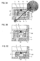
- Figs. 3A, 3B and 3C show sectional views in which the microphone assembly 3 is placed in the microphone storage part 11 of the housing 10.
- the microphone 4 is housed in a casing 8.
- the casing 8 which houses the microphone 4 is placed in a space in the rubber piece 5 while the rear face 4B of the microphone 4 faces the recess 52 in the rubber piece 5 and is communicated with that sound-hole stub 61 of the holder 6 which is located on the side face 1R of the housing.
- the front face 4F of the microphone 4 is communicated with that sound-hole stub 61 of the holder 6 which is located from a side face of the casing 8 to the front face 1F of the housing.
- the sound-hole stubs 61 of the holder 6 are placed in the sound holes 12S and 12M of the housing 10 (microphone storage part 11).
- the microphone 4 picks up sound through the sound holes 12M and 12S in the side face 1R and the front face 1F of the microphone storage part 11.
- the direction extending from the front sound hole 12S in the front face 1F of the microphone storage part 11 of the housing to the lateral sound hole 12M in the side face 1R of the microphone storage part 11 and represented by a thick arrow in the figure is referred to as a directional axis.
- the microphone assembly 3 the sensitivity with which sound is picked up along the direction of the directional axis depends on the directional sensitivity of the microphone 4.
- FIG. 3A represents a sensitivity area and has intermediate directional characteristics between omnidirectional and bidirectional characteristics as is the case with the directivity of the microphone 4.
- the sensitivity is extremely higher on the front face 1F of the housing 10 than on a rear face 1B of the housing 10.
- Fig. 3A the microphone 4 is housed in the casing 8, which is housed in the rubber piece 5, which in turn is housed in the holder 6.
- Figs. 3B and 3C show other configuration examples of the microphone assembly 3, where Fig. 3B shows a structure similar to the structure in Fig. 2A except that the casing 8 has been omitted while Fig. 3C shows a structure in which the holder 6 has been omitted in addition. That is, Fig. 3B shows a structure in which the rubber piece 5 containing the microphone 4 is housed directly in the holder 6 while maintaining communicating paths running from the front face and rear face of the microphone 4 to the sound holes 12S and 12M in the front face and side face of the microphone storage part 11.
- Fig. 3C shows a structure in which the rubber piece 5 combining the role of the holder 6 in Fig. 3B can be housed and fixed in the microphone storage part 11. This makes it possible to eliminate the casing 8 or the holder 6, and thus reduce the number of parts.
- Fig. 4 shows directions of directional axes and sound sensitivities therein when the microphone assemblies 3 are installed in the upper left and right front corners of the housing 10 of the cell phone shown in Fig. 1.
- the microphone assemblies 3 By laying out the microphone assemblies 3 in this way, it is possible to collect stereo sound behind the housing 10 with high sensitivity. For example, by picking up two sources of sound produced by subjects of a camera installed on the back face of the housing 10, it is possible to obtain stereo sound for movie recording, videophone, or the like efficiently with high sensitivity. Also, as shown in Fig.
- the microphone assembly 3 can be placed stably in the microphone storage part 11 in the corner where the front face 1F and side face 1L (or 1R) of the housing 10 intersect, making it possible to maintain high sound-acquisition sensitivity along the direction of the directional axis. Since the two microphone assemblies 3 are installed in a small portable electronic apparatus such as a cell phone, preferably they are placed as far away from each other as possible. Also, it is preferable to install them in a horizontally symmetrical manner (or in a vertically symmetrical manner if viewed from a different angle) for the purpose of acquiring stereo sound.
- Fig. 5 is a schematic diagram showing two microphone assemblies 3 placed with their directional axes spaced approximately 120 degrees apart.
- the two microphone assemblies 3 are placed in two corners of the housing 10.
- a sound hole referred to as an auxiliary sound hole
- 61S on the front face 1F of the housing 10 of the holder 6 containing the microphone 4
- a sound hole referred to as a main sound hole
- 61M of the sound-hole stub 61
- the holders 6 (the microphone assemblies 3) can be placed stably in corners of the housing 10 as shown in Fig. 5 regardless of the angle formed by the directional axes. This makes layout and wiring of the microphone assemblies 3 easier.
- the angle between their directional axes is set to 120 degrees, but it may be set otherwise within a range of 120 ⁇ 30 degrees.
- the angle between the directional axes may be varied depending on attributes and operation of the sound source from which sound is acquired or preferences of the user who listens to the stereo sound and listenability of the stereo sound. Generally, increasing the angle between the directional axes gives a sense of stereo, but increasing it too much will cause the phenomenon of so-called "hole effect," making it difficult to pick up sound in the center. However, a wide angle between the directional axes which will cause a hole effect may be used depending on an object or user preferences.
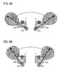
- Figs. 6A and 6B show a case in which the angle between the directional axes is increased and a case in which the angle between the directional axes is decreased, respectively.
- the angle between the directional axes can be adjusted through adjustment of positional relationship between the main sound hole 6 1 M and auxiliary sound hole 61 S of each microphone assembly 3.
- the microphone assemblies 3 are flattened by reducing their depth and the auxiliary sound holes 61 S are moved away from the main sound holes 61 M in a direction parallel to the front face whereas in Fig. 6B, the depth of the microphone assemblies 3 is increased and the auxiliary sound holes 61S are brought close to the main sound holes 6 1 M in a direction parallel to the front face.
- FIGs. 6A and 6B show structures in which the angle between the directional axes is adjusted in advance according to the object from which sound is acquired or at the request of the user
- Figs. 7A, 7B, and 8 show structures which allow the user to adjust the angle between the directional axes.
- two slide plates 91 each with a hole 90, are installed between the microphone assemblies 3 and the front face 1F of the housing 10.
- the two sound holes 12S in the front face are widened in the direction of a straight line connecting them.
- the width of the holes 90 in the slide plates 91 is equal to or less than half the width of the sound holes 12S in the front face.
- Figs. 7C and 7D show other variations of Figs. 7A and 7B.
- two slide plates 91 are installed outside the front face 1F of the housing 10 and the positions of the auxiliary sound holes 61 S can be varied relative to the positions of the main sound holes 61 M.
- Fig. 7C shows how the two slide plates 91 are brought close to each other, moving the auxiliary sound holes 61S away from the main sound holes 61M to increase the angle between the directional axes
- Fig. 7D shows how the two slide plates 91 are moved away from each other, bringing the auxiliary sound holes 61S close to the main sound holes 61M to decrease the angle between the directional axes.
- Fig. 8 shows concrete examples of configuration examples shown in Figs. 7C and 7D, where Figs. 8A and 8B are exploded perspective views, Figs. 8C and 8E show how the slide plates 91 are moved away from each other, bringing the auxiliary sound holes close to the main sound holes to decrease the angle between the directional axes, and Figs. 8D and 8F show how the slide plates 91 are brought close to each other, moving the auxiliary sound holes away from the main sound holes to increase the angle between the directional axes.
- the two rectangular slide plates 91 are fitted in the front face 1F of the housing 10, and an elongated slide recess 111 is formed to allow the slide plates 91 to slide along.
- two sound holes 12S elongated in the lengthwise direction of the slide recess 111 are formed at longitudinal intervals.
- Guide grooves 111 a are formed in opposite side walls along the lengthwise direction of the slide recess 111 and two lateral edges of the slide plates 91 are slidably fitted in the guide grooves 111a.
- the slide plates 91 are fitted in the slide recess 111 in such a way that their short sides will face each other.
- Respective holes 90 are formed in the slide plates 91 in such a way as to overlap the elongated sound holes 12S when the slide plates 91 are mounted in the slide recess 111, so that the holes 90 will change communicating position of the sound holes 12S as the slide plates 91 slide over the housing 10.
- arms 91a are formed at diagonally opposite ends of those short sides of the two slide plates 91 which face each other, extending toward each other in a direction parallel to the sliding direction.
- An engagement shaft 91 c perpendicular to the top face of the slide plate 91 is formed at the tip of each arm 91 a.
- a connecting rod 92 is installed to turnably connect the engagement shafts 91c of the two arms 91 a.
- Connecting holes 92a elongated in the lengthwise direction of the connecting rod are formed at both ends of the connecting rod, and the engagement shafts 91 c of the arms 91a are inserted into and engaged with them.
- a shaft 93 of a motor 94 (Fig.
- the slide plates 91 are moved away from each other, bringing the auxiliary sound holes 61 S close to the main sound holes 6 1 M to decrease the angle between the directional axes as shown in Fig. 7D while in the state shown in Figs. 8D and 8F, the slide plates 91 are brought close to each other, moving the auxiliary sound holes 61S away from the main sound holes 61M to increase the angle between the directional axes as shown in Fig. 7C.
- this embodiment has the effect of cutting noise coming from behind a cell phone using two microphone assemblies which provide stereo sound, as a noise canceller during a normal telephone conversation.
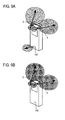
- this embodiment has a microphone assembly 100 (indicated by a broken line) for normal telephone conversations as shown in Figs. 9A and 9B in addition to the two microphone assemblies 3 for stereo sound.
- the two microphone assemblies 3 for stereo sound is operated as shown in Fig. 9B while in normal call mode as shown in Fig. 9A, the two microphone assemblies 3 for stereo sound is used as a noise-cancelling sound collector, as required, to cut noise coming from behind the apparatus.
- Fig. 9A the two microphone assemblies 3 for stereo sound is used as a noise-cancelling sound collector, as required, to cut noise coming from behind the apparatus.
- FIG. 10 is a simplified circuit diagram of the noise canceller, where the two microphone assemblies 3 for stereo sound are connected to a mixer 102 via an inverter circuit 101 and the microphone assembly 100 for telephone conversations is connected directly to the mixer 102.
- the mixer 102 which functions as a noise cancelling means, cancels out noises from the microphone assemblies 3 and 100.
- a switch 103 is used to switch among noise cancelling operation, stereo operation, and normal call mode without noise cancelling.
- Fig. 11 shows two microphone assemblies for stereo sound: when a sound source is distant from an apparatus 1 shown in Fig. 11A, stereo sound input is captured and when a sound source is close to the apparatus 1 shown in Fig. 11B, monophonic sound input is captured using only one of the microphone assemblies without operating the other microphone assembly. By capturing nearby sound using only one of the microphone assemblies in this way, it is possible to make a phone call using the other microphone assembly.
- a switch 104 which is a deactivating means, as shown in Fig. 12.
- the present invention is also applicable to other portable electronic apparatus including information communication apparatus such as PDAs, personal computers, digital still cameras, digital video cameras, and toys.
Landscapes
- Engineering & Computer Science (AREA)
- Signal Processing (AREA)
- Physics & Mathematics (AREA)
- Acoustics & Sound (AREA)
- Health & Medical Sciences (AREA)
- Otolaryngology (AREA)
- Telephone Set Structure (AREA)
- Details Of Audible-Bandwidth Transducers (AREA)
- Electrostatic, Electromagnetic, Magneto- Strictive, And Variable-Resistance Transducers (AREA)
Applications Claiming Priority (2)
| Application Number | Priority Date | Filing Date | Title |
|---|---|---|---|
| JP2005155868A JP4344342B2 (ja) | 2005-05-27 | 2005-05-27 | 携帯電子機器 |
| PCT/JP2006/310461 WO2006126641A1 (ja) | 2005-05-27 | 2006-05-25 | マイクロホン付き携帯電子機器 |
Publications (2)
| Publication Number | Publication Date |
|---|---|
| EP1885155A1 true EP1885155A1 (de) | 2008-02-06 |
| EP1885155A4 EP1885155A4 (de) | 2009-12-16 |
Family
ID=37452065
Family Applications (1)
| Application Number | Title | Priority Date | Filing Date |
|---|---|---|---|
| EP06746840A Withdrawn EP1885155A4 (de) | 2005-05-27 | 2006-05-25 | Tragbare elektronische vorrichtung mit mikrofonen |
Country Status (7)
| Country | Link |
|---|---|
| US (1) | US20090129621A1 (de) |
| EP (1) | EP1885155A4 (de) |
| JP (1) | JP4344342B2 (de) |
| KR (1) | KR101094808B1 (de) |
| CN (1) | CN101161030A (de) |
| TW (1) | TW200714117A (de) |
| WO (1) | WO2006126641A1 (de) |
Cited By (2)
| Publication number | Priority date | Publication date | Assignee | Title |
|---|---|---|---|---|
| WO2014012582A1 (en) * | 2012-07-18 | 2014-01-23 | Huawei Technologies Co., Ltd. | Portable electronic device with directional microphones for stereo recording |
| WO2014012583A1 (en) * | 2012-07-18 | 2014-01-23 | Huawei Technologies Co., Ltd. | Portable electronic device with directional microphones for stereo recording |
Families Citing this family (16)
| Publication number | Priority date | Publication date | Assignee | Title |
|---|---|---|---|---|
| KR100865147B1 (ko) | 2007-07-09 | 2008-10-24 | 엘지전자 주식회사 | 휴대 단말기 |
| US20090052686A1 (en) * | 2007-08-23 | 2009-02-26 | Fortemedia, Inc. | Electronic device with an internal microphone array |
| US20090052715A1 (en) * | 2007-08-23 | 2009-02-26 | Fortemedia, Inc. | Electronic device with an internal microphone array |
| JP5045929B2 (ja) * | 2008-01-17 | 2012-10-10 | ティアック株式会社 | ポータブル録音装置 |
| JP2011082723A (ja) | 2009-10-06 | 2011-04-21 | Hosiden Corp | 単一指向性マイクロホン |
| JP5311575B2 (ja) * | 2009-10-13 | 2013-10-09 | 株式会社オーディオテクニカ | マイクロホン |
| TWM394026U (en) * | 2010-07-28 | 2010-12-11 | Jin-Sheng Lin | Protective cover containing built-in amplifying channel |
| DE102010042797B4 (de) * | 2010-10-22 | 2017-09-14 | Sennheiser Electronic Gmbh & Co. Kg | Kondensatormikrofon |
| JP5731900B2 (ja) * | 2011-05-19 | 2015-06-10 | 株式会社オーディオテクニカ | ステレオマイクロホン |
| JP5786654B2 (ja) * | 2011-11-02 | 2015-09-30 | ティアック株式会社 | ステレオマイク装置 |
| US9510121B2 (en) * | 2012-12-06 | 2016-11-29 | Agency For Science, Technology And Research | Transducer and method of controlling the same |
| JP6213871B2 (ja) * | 2012-12-27 | 2017-10-18 | パナソニックIpマネジメント株式会社 | 防水マイク装置 |
| KR101455077B1 (ko) * | 2013-06-26 | 2014-10-27 | 주식회사 비에스이 | 퍼스널 네비게이션 기능을 위한 고기능성 마이크 모듈 조립체 |
| JP6265425B2 (ja) * | 2014-05-16 | 2018-01-24 | 株式会社オーディオテクニカ | マイクロホン装置およびマイクロホンキャップ |
| JP2019021966A (ja) * | 2017-07-11 | 2019-02-07 | オリンパス株式会社 | 収音装置および収音方法 |
| JP7698454B2 (ja) * | 2021-04-06 | 2025-06-25 | シャープ株式会社 | 電子機器 |
Family Cites Families (10)
| Publication number | Priority date | Publication date | Assignee | Title |
|---|---|---|---|---|
| GB1592168A (en) * | 1976-11-29 | 1981-07-01 | Oticon Electronics As | Hearing aids |
| JPS58104098U (ja) * | 1981-12-30 | 1983-07-15 | 株式会社東芝 | トランスジユ−サ |
| JPH025977U (de) * | 1988-06-23 | 1990-01-16 | Sony Corp | |
| US5651074A (en) * | 1995-05-11 | 1997-07-22 | Lucent Technologies Inc. | Noise canceling gradient microphone assembly |
| US6108415A (en) * | 1996-10-17 | 2000-08-22 | Andrea Electronics Corporation | Noise cancelling acoustical improvement to a communications device |
| JP2002135880A (ja) | 2000-10-20 | 2002-05-10 | Primo Co Ltd | 一次音圧傾度型マイクロホン及び携帯端末装置 |
| US7206418B2 (en) * | 2001-02-12 | 2007-04-17 | Fortemedia, Inc. | Noise suppression for a wireless communication device |
| JP2004056408A (ja) * | 2002-07-19 | 2004-02-19 | Hitachi Ltd | 携帯電話端末 |
| JP4072679B2 (ja) * | 2003-02-20 | 2008-04-09 | ソニー株式会社 | マイクロホン装置および音声記録再生装置 |
| JP4606706B2 (ja) | 2003-06-24 | 2011-01-05 | ヤマハ株式会社 | 携帯電話端末 |
-
2005
- 2005-05-27 JP JP2005155868A patent/JP4344342B2/ja not_active Expired - Fee Related
-
2006
- 2006-05-12 TW TW095116823A patent/TW200714117A/zh not_active IP Right Cessation
- 2006-05-25 CN CNA2006800128776A patent/CN101161030A/zh active Pending
- 2006-05-25 WO PCT/JP2006/310461 patent/WO2006126641A1/ja not_active Ceased
- 2006-05-25 EP EP06746840A patent/EP1885155A4/de not_active Withdrawn
- 2006-05-25 KR KR1020077021301A patent/KR101094808B1/ko not_active Expired - Fee Related
- 2006-05-25 US US11/920,821 patent/US20090129621A1/en not_active Abandoned
Cited By (6)
| Publication number | Priority date | Publication date | Assignee | Title |
|---|---|---|---|---|
| WO2014012582A1 (en) * | 2012-07-18 | 2014-01-23 | Huawei Technologies Co., Ltd. | Portable electronic device with directional microphones for stereo recording |
| WO2014012583A1 (en) * | 2012-07-18 | 2014-01-23 | Huawei Technologies Co., Ltd. | Portable electronic device with directional microphones for stereo recording |
| CN104429049A (zh) * | 2012-07-18 | 2015-03-18 | 华为技术有限公司 | 具有用于立体声录音的麦克风的便携式电子装置 |
| US9247334B2 (en) | 2012-07-18 | 2016-01-26 | Huawei Technologies Co., Ltd. | Portable electronic device |
| CN104429049B (zh) * | 2012-07-18 | 2016-11-16 | 华为技术有限公司 | 具有用于立体声录音的麦克风的便携式电子装置 |
| US9521500B2 (en) | 2012-07-18 | 2016-12-13 | Huawei Technologies Co., Ltd. | Portable electronic device with directional microphones for stereo recording |
Also Published As
| Publication number | Publication date |
|---|---|
| US20090129621A1 (en) | 2009-05-21 |
| KR20080011648A (ko) | 2008-02-05 |
| EP1885155A4 (de) | 2009-12-16 |
| KR101094808B1 (ko) | 2011-12-16 |
| WO2006126641A1 (ja) | 2006-11-30 |
| JP4344342B2 (ja) | 2009-10-14 |
| JP2006333222A (ja) | 2006-12-07 |
| CN101161030A (zh) | 2008-04-09 |
| TWI314427B (de) | 2009-09-01 |
| TW200714117A (en) | 2007-04-01 |
Similar Documents
| Publication | Publication Date | Title |
|---|---|---|
| EP1885155A1 (de) | Tragbare elektronische vorrichtung mit mikrofonen | |
| US12212943B2 (en) | Wireless headset | |
| CN104618570B (zh) | 多麦克风的音频捕获 | |
| CN103460714B (zh) | 耳内传声器及耳内传声器用电压控制装置 | |
| JP2609822B2 (ja) | 送話器 | |
| US9762991B2 (en) | Passive noise-cancellation of an in-ear headset module | |
| JP2004534449A (ja) | 携帯電話用の手を使わなくてよい小型アダプタ | |
| TW200421823A (en) | Mobile phone using bone conduction speaker | |
| CN104429050A (zh) | 具有用于立体声音频录音的麦克风的便携式电子装置 | |
| CN104429049A (zh) | 具有用于立体声录音的麦克风的便携式电子装置 | |
| CN101151875A (zh) | 便携式终端 | |
| CN114070910A (zh) | 壳体及电子设备 | |
| CN101080917A (zh) | 带有扬声器声音重定向的移动终端 | |
| JP6314298B2 (ja) | 単一指向性接話マイクロホンおよびマイクロホンキャップ | |
| JP2003110676A (ja) | 携帯型通信機器及び同機器用マイクロホン装置 | |
| CN101305639A (zh) | 便携式终端 | |
| JP2007300513A (ja) | マイクロフォン装置 | |
| US20060067547A1 (en) | Stereo portable electronic device | |
| CN211860488U (zh) | 无线耳机 | |
| CN110868669A (zh) | 指向性麦克风 | |
| JP2006157199A (ja) | スライド型携帯端末 | |
| US9888308B2 (en) | Directional microphone integrated into device case | |
| CN218679365U (zh) | 一种电子设备 | |
| CN216600003U (zh) | 低风噪耳机组件及耳机 | |
| CN115643332B (zh) | 移动终端 |
Legal Events
| Date | Code | Title | Description |
|---|---|---|---|
| PUAI | Public reference made under article 153(3) epc to a published international application that has entered the european phase |
Free format text: ORIGINAL CODE: 0009012 |
|
| 17P | Request for examination filed |
Effective date: 20071212 |
|
| AK | Designated contracting states |
Kind code of ref document: A1 Designated state(s): DE FI FR SE |
|
| DAX | Request for extension of the european patent (deleted) | ||
| RBV | Designated contracting states (corrected) |
Designated state(s): DE FI FR SE |
|
| A4 | Supplementary search report drawn up and despatched |
Effective date: 20091113 |
|
| RIC1 | Information provided on ipc code assigned before grant |
Ipc: H04R 19/01 20060101ALN20091110BHEP Ipc: H04R 5/027 20060101AFI20061218BHEP Ipc: H04M 1/03 20060101ALI20091110BHEP Ipc: H04R 1/38 20060101ALI20091110BHEP |
|
| STAA | Information on the status of an ep patent application or granted ep patent |
Free format text: STATUS: THE APPLICATION HAS BEEN WITHDRAWN |
|
| 18W | Application withdrawn |
Effective date: 20150129 |