EP1885304B1 - Instrument d'irrigation et/ou drainage - Google Patents
Instrument d'irrigation et/ou drainage Download PDFInfo
- Publication number
- EP1885304B1 EP1885304B1 EP06722951.8A EP06722951A EP1885304B1 EP 1885304 B1 EP1885304 B1 EP 1885304B1 EP 06722951 A EP06722951 A EP 06722951A EP 1885304 B1 EP1885304 B1 EP 1885304B1
- Authority
- EP
- European Patent Office
- Prior art keywords
- appliance
- wall
- chamber
- sealed chamber
- wafer
- Prior art date
- Legal status (The legal status is an assumption and is not a legal conclusion. Google has not performed a legal analysis and makes no representation as to the accuracy of the status listed.)
- Not-in-force
Links
- 238000003973 irrigation Methods 0.000 title claims description 9
- 230000002262 irrigation Effects 0.000 title claims description 9
- 230000008878 coupling Effects 0.000 claims description 58
- 238000010168 coupling process Methods 0.000 claims description 58
- 238000005859 coupling reaction Methods 0.000 claims description 58
- 239000000853 adhesive Substances 0.000 claims description 43
- 230000001070 adhesive effect Effects 0.000 claims description 43
- 239000000463 material Substances 0.000 claims description 12
- 239000012530 fluid Substances 0.000 claims description 9
- 206010016717 Fistula Diseases 0.000 claims description 5
- 230000003890 fistula Effects 0.000 claims description 5
- 238000007789 sealing Methods 0.000 claims description 4
- 206010052428 Wound Diseases 0.000 description 27
- 208000027418 Wounds and injury Diseases 0.000 description 27
- 239000007788 liquid Substances 0.000 description 16
- 239000006260 foam Substances 0.000 description 11
- 230000000630 rising effect Effects 0.000 description 8
- 238000005452 bending Methods 0.000 description 4
- 238000004140 cleaning Methods 0.000 description 4
- 238000010276 construction Methods 0.000 description 3
- 210000003608 fece Anatomy 0.000 description 3
- 239000004033 plastic Substances 0.000 description 3
- 238000009877 rendering Methods 0.000 description 3
- 239000000126 substance Substances 0.000 description 3
- 210000000436 anus Anatomy 0.000 description 2
- 230000004888 barrier function Effects 0.000 description 2
- 230000008901 benefit Effects 0.000 description 2
- 230000001276 controlling effect Effects 0.000 description 2
- 230000007423 decrease Effects 0.000 description 2
- 238000007689 inspection Methods 0.000 description 2
- 238000003466 welding Methods 0.000 description 2
- 230000008859 change Effects 0.000 description 1
- 239000000470 constituent Substances 0.000 description 1
- 238000005520 cutting process Methods 0.000 description 1
- 230000006837 decompression Effects 0.000 description 1
- 230000000694 effects Effects 0.000 description 1
- 230000003028 elevating effect Effects 0.000 description 1
- 229920001821 foam rubber Polymers 0.000 description 1
- 230000036541 health Effects 0.000 description 1
- 239000000416 hydrocolloid Substances 0.000 description 1
- 238000000034 method Methods 0.000 description 1
- 229920003052 natural elastomer Polymers 0.000 description 1
- 229920001194 natural rubber Polymers 0.000 description 1
- 239000002861 polymer material Substances 0.000 description 1
- 229920001296 polysiloxane Polymers 0.000 description 1
- 230000002028 premature Effects 0.000 description 1
- 230000008569 process Effects 0.000 description 1
- 230000001105 regulatory effect Effects 0.000 description 1
- 239000007787 solid Substances 0.000 description 1
- 230000000087 stabilizing effect Effects 0.000 description 1
- 238000003860 storage Methods 0.000 description 1
- 238000007460 surgical drainage Methods 0.000 description 1
- 230000009182 swimming Effects 0.000 description 1
- 229920003051 synthetic elastomer Polymers 0.000 description 1
- 239000005061 synthetic rubber Substances 0.000 description 1
Images


Classifications
-
- A—HUMAN NECESSITIES
- A61—MEDICAL OR VETERINARY SCIENCE; HYGIENE
- A61F—FILTERS IMPLANTABLE INTO BLOOD VESSELS; PROSTHESES; DEVICES PROVIDING PATENCY TO, OR PREVENTING COLLAPSING OF, TUBULAR STRUCTURES OF THE BODY, e.g. STENTS; ORTHOPAEDIC, NURSING OR CONTRACEPTIVE DEVICES; FOMENTATION; TREATMENT OR PROTECTION OF EYES OR EARS; BANDAGES, DRESSINGS OR ABSORBENT PADS; FIRST-AID KITS
- A61F5/00—Orthopaedic methods or devices for non-surgical treatment of bones or joints; Nursing devices ; Anti-rape devices
- A61F5/44—Devices worn by the patient for reception of urine, faeces, catamenial or other discharge; Colostomy devices
- A61F5/4404—Details or parts
-
- A—HUMAN NECESSITIES
- A61—MEDICAL OR VETERINARY SCIENCE; HYGIENE
- A61F—FILTERS IMPLANTABLE INTO BLOOD VESSELS; PROSTHESES; DEVICES PROVIDING PATENCY TO, OR PREVENTING COLLAPSING OF, TUBULAR STRUCTURES OF THE BODY, e.g. STENTS; ORTHOPAEDIC, NURSING OR CONTRACEPTIVE DEVICES; FOMENTATION; TREATMENT OR PROTECTION OF EYES OR EARS; BANDAGES, DRESSINGS OR ABSORBENT PADS; FIRST-AID KITS
- A61F5/00—Orthopaedic methods or devices for non-surgical treatment of bones or joints; Nursing devices ; Anti-rape devices
- A61F5/44—Devices worn by the patient for reception of urine, faeces, catamenial or other discharge; Colostomy devices
- A61F5/442—Devices worn by the patient for reception of urine, faeces, catamenial or other discharge; Colostomy devices having irrigation ports or means
Definitions
- the invention relates to appliances for ostomy, fistula, wound or drain site treatment.
- the invention further relates to means for facilitating the use of such collecting devices.
- fistulae and wounds appliances comprising a collecting bag
- the appliance has an access opening for inspecting, cleaning and/or treating the skin site.
- the appliance may comprise a body side member in the form of an adhesive wafer secured to the skin and with an opening for receiving the stoma, fistulae or wound.
- the collecting bag attached, optionally with means for irrigation and/or drainage, such as inlets and outlets.
- the bag may be provided with an access opening in the form of a window, which can be closed with a lid.
- the lid When it is time for cleaning or rinsing the skin site comprising the stoma, wound or fistulae, the lid is removed, and the site may be inspected or treated.
- a problem relating to such appliances is to prevent body liquids and excreta from exiting out of the collecting bag, when the lid is removed and during treatment of the site.
- US patents Nos. 6,093,160 and 6,110,197 discloses a wound treatment device comprising an adhesive wafer for adhering to the skin and a support member, preferably in the form of a ring-shaped foam cushion.
- the support member is attached to the adhesive wafer on one surface, and on the opposite surface is provided an access opening with means for attaching a lid.
- the support member provides a constant distance between the lid and the wound site, thus protecting the wound and facilitating cleaning of the wound and controlling the liquid.
- the support member provides a constantly raised portion and is not suitable for larger wounds and/or application on curved or protruding body parts, as the construction is rather stiff.
- US patent No. 3,902,496 discloses a surgical drainage appliance, prepared from thin plastic material and comprises gas or foam filled plastic cushions located on either side of inlet for the stoma so as to protect it in use.
- the cushions are mounted inside the bag and are permanently inflated/foam filled, thus the amount of gas/foam cannot be adjusted during use.
- the bag is closed without a window, and the cushions are located right next to the stoma, for protecting this.
- a collecting bag for an artificial anus said bag comprises an inflatable cushion that may be inflated to a desired level in order to protect the artificial anus.
- the cushion is preferably in the form of a half-circle, mounted over and around a part of the stoma. The cushion is mounted inside the bag.
- Yet another object is to provide means for stabilizing the wall in upright position and at the same time facilitating that the coupling flange is able to move substantially independently of the adhesive wafer.
- Still another object of the present invention is to provide an appliance wherein the walls may be raised to a stable, substantially upright position and collapsed to a substantially flat position as desired.
- the invention relates to an appliance for irrigation and/or drainage, which appliance comprising a body side member comprising an adhesive wafer for securing the appliance to the patient's skin, said wafer can be provided with an aperture for receiving a stoma, surrounding a wound, a fistula or a drainage site, a wall of flexible material, the wall comprising a rear wall and a front wall, the rear wall being attached to the wafer and having an opening suitable for surrounding the surface area of the skin to be cleansed and a front wall being provided with a coupling flange adapted for removable coupling and sealing to matching coupling means, the wall and the body side member defining a reservoir, a sealed chamber, being separate from the reservoir, said chamber when inflated, provides a distance between the adhesive wafer and the coupling flange.
- the sealed chamber When the sealed chamber is not inflated, the wall is collapsed and the appliance is substantially flat and two-dimensional, and does not take up unnecessary space during storage and when applied to a body part.
- the sealed chamber When the wound or fistulae needs inspection, cleaning or other treatment, the sealed chamber may be inflated, thus raising the walls of the appliance and creating a distance between the flange and the wafer. The erected wall and the wafer may thus define a reservoir. The raised walls decrease the risk of splashing and leakage during the rinsing process.
- a lid When cleansing/inspection is finished, a lid may be applied and the chamber can be deflated again returning the appliance to its original flat configuration. Alternatively, the chamber may stay constantly inflated, thus creating a buffer zone around the fistulae or wound.
- the sealed chamber may be a part of the wall or connected to the wall and constitutes a delimited volume being air and liquid tight separated from the reservoir.
- the sealed chamber may be contained in the reservoir, i.e. being in the form of a balloon along the inside or outside wall of the reservoir, or be a part of the wall, but the chamber is designed in such a way that it is possible to directly access the wound or fistulae through the opening of the appliance.
- the sealed chamber is following a major part of the circumference of the wall of the appliance, e.g. being in the form of a circular or oval ring or an open ring, such as a horseshoe-configuration.
- the chamber may be placed inside the walls, in the reservoir, or the chamber may be placed on the outside of the wall. It may be preferred to have the chamber on the outside of the walls as it may take up space in the reservoir and may create undesired corners that may accumulate contaminated material.
- the reservoir is accessible through the opening when the chamber is inflated.
- Prior art shows appliances wherein the reservoir itself is inflated. This solution suffers from the drawback that the reservoir can only be attended through a closed system, as the reservoir otherwise will collapse if the reservoir is opened.
- the sealed chamber is separate from the reservoir and can thus be inflated independently of the reservoir and the walls of the appliance can thus be erected without inflating the reservoir.
- any suitable fluid such as a gas or a liquid may inflate the chamber.
- the fluid is a gel.
- the chamber is inflated by air.
- the sealed chamber may be prepared from any suitable material being flexible and able to detain gas and/or liquid.
- the chamber may be in the form of a tube; prepared from a tube-like structure or it may be in the form of one or more sheets being sealed together to provide an inflatable chamber.
- the chosen material for the chamber should be flexible but yet rigid enough to support and keep the two elements in a preferred stable distance.
- the sealed chamber constitutes a part of the wall.
- the sealed chamber may be an integrated part of the appliance.
- the chamber may constitute a part of the wall of the appliance of the invention or it may be substantially independent of the wall.
- the chamber may be attached to the wall by a single point or by sharing a part of the wall. It is preferred that the part of the wall that may constitute a part of the chamber is less than 50% of the wall. The larger part of the wall constituting the chamber, the less independency in the movement of the wall is achieved.
- the height of the sealed chamber, when expanded, is preferably smaller than the height of a fully erected wall, in order to provide space for flexibility.
- the height is less than 75 % more preferred more preferred less than 60% and most preferred less than 50%.
- the chamber may be attached to the coupling flange or to the wall next to the coupling flange or the chamber may be attached to the adhesive wafer or the front wall next to the wafer.
- the wall of the appliance comprises a rear wall and a front wall.
- the front and the rear wall may be sealed together in such a manner that the two walls are superimposed when the wall I collapsed.
- the front and rear wall may also be prepared as a single sheet, thus folding e.g. like an accordion when collapsed. This embodiment may however be complicated to produce, so the embodiment with two connected sheets may be preferred.
- the wall may be prepared by folding and welding the sheet in such a way, that it creates a "box form" when it is in use. Folding the film several times, or forming or welding many layers of film together can achieve an accordion design, which can be adjusted to a varying change of position rise.
- the wall of the appliance may be raised when the skin site is attended, and that the wall is able to stay erected without being actively supported by the user, e.g. held by the hand.
- the erected wall provides a reservoir over the skin site, securing any liquids around the skin site stays inside the reservoir and thus decreases unhygienic situations from leakage and overflow.
- the construction is still flexible due to a balloon effect of the sealed chamber and not as rigid as a foam structure.
- Rising of the coupling flange is today done by manually erecting e.g. by grabbing the coupling flange with the fingers and elevating, thus erecting the wall of the appliance. Only the design and stiffness of the wall ensures the preferred distance momentarily.
- the wall is having a tendency to collapse thus bringing the appliance to a substantially flat configuration and may cause body liquid to exit out of the bag, thus creating a hygienic problem.
- a solution to this problem is to have a surrounding protrusion profile in the attached coupling part, which can function as a barrier wall, while the detachable coupling part in the form of a lid or collecting/drainage bag is removed from the access opening.
- an appliance If an appliance is applied to a curved body part it may be exposed to severe stress from twisting and bending. Furthermore, when the wall is raised, the coupling flange, typically being more rigid than the wall, may also twist if it has to follow the adhesive wafer. Stress may be build up in the appliance leading to detachment from the skin, discomfort for the patient and difficulties when attaching a lid or bag to the coupling flange.
- the sealed chamber when inflated, supports at least one of the walls.
- the sealed chamber when inflated, supports the rear wall.
- the sealed chamber when inflated, supports the front wall.
- the wall of the appliance By having the sealed chamber supporting one of the walls of the collecting chamber, it may be possible for the wall of the appliance to be supported in such way that at least one wall can be straightened out and due to some resistance against crumpling up the other wall stays partly straightened out, and hereby rendering it possible level the coupling flange and thus facilitating the connection of the lid to the coupling flange.
- the adhesive wafer follows the contours of the body part, while the raised coupling flange may enter a more planar configuration, substantially independent of the configuration of the wafer.
- the sealed chamber may be connected to the adhesive wafer or to the wall near or next to the adhesive wafer.
- the sealed chamber may erect the rear wall.
- the front wall may be partly erected by influence of the coupling flange, the flange having a higher rigidity and thus an inherent desire to revert to its initial planar configuration.
- the sealed chamber is connected to the coupling flange or to the front wall near or next to the flange.
- the sealed chamber erects the front wall when inflated and fully or partly the rear wall. As the sealed chamber is placed right under the coupling flange, it will contribute to the levelling of the flange, while the rear wall may serve as a buffer, absorbing the stress of twisting from the adhesive wafer.
- the wall may be provided with an opening, preferably in the form of an inlet and/or outlet opening for entering fluids in or out of the reservoir and for accessing the skin site.
- the sealed chamber may be inflated and deflated during use of the appliance.
- the chamber may be inflated when the skin site is attended, and deflated when the appliance is closed with a lid or collection bag.
- the chamber may also be used as permanently inflated if that may be desired.
- the adhesive wafer of the appliance of the present invention may be made from any appropriate skin friendly material known per se for the purpose and may also comprise a top film known per se.
- the skin-friendly adhesive may be any skin-friendly adhesive known per se, e.g. an adhesive comprising hydrocolloids or other moisture absorbing constituents for prolonging the time of use.
- the coupling flange for attaching a collection bag or a lid may be a system known per se comprising matching coupling rings or matching flanges and adhesive surfaces.
- the adhesive wafer may be provided with an aperture corresponding to the contour of the stoma, fistulae or wound.
- the wafer may be provided with an aperture being tailor-fit to the patient, or a drawing of the desired contours of the aperture may be printed on the wafer for cutting before application.
- the wafer is provided with a standard cut aperture.
- the appliance may be delivered without an aperture leaving opportunity for the health care personnel to provide a custom made aperture in the wafer.
- the invention also relates to an sealed chamber for use with an appliance for irrigation and/or drainage, which appliance comprising a body side member comprising an adhesive wafer for securing the appliance to the patient's skin, said wafer or pad can be adapted for receiving a stoma, surrounding a wound, a fistula or a drainage site, a wall of flexible material, the wall comprising a rear wall being attached to the wafer and having an opening suitable for surrounding the surface area of the skin to be cleansed and a front wall being provided with a coupling flange defining an aperture/ window of the wall, the wall and the body side member defining a reservoir, and wherein the sealed chamber, being separate from the reservoir, can be inflated by filling with a fluid, said chamber, when inflated, provides a distance between the adhesive wafer and the coupling flange.
- the sealed chamber may be an integrated part of the appliance or it may be a separate unit. In one embodiment of the invention the chamber is detachable from the appliance.
- the sealed chamber may extend along the outer periphery of the wall.
- the chamber may be in the form of a closed ring, but is preferably and open ring.
- the open ring is provided with means for connecting the end portions, rendering it possible to attach the two end portions of the ring to each other's to achieve a closed ring.
- the connecting means may be any suitable means known per se, such as adhesive, Velcro or a mechanical lock.
- the chamber extend only along a part of the wall, e.g. having the shape of a horseshoe.
- the sealed chamber is provided with a valve for filling or emptying the fluid.
- the chamber may be inflated with any suitable liquid or gas, especially air.
- the valve may be any kind of valve suitable for the purpose.
- the kind of valve used for the inflating the sealed chamber may for example be of the type known from inflatable mattresses or swimming rings, where it is possible to connect an inflation device, such as a pump, inflate the substance and remove the device, without the substance escaping out of the valve. By pushing the valves sides together, it is possible to empty the inflated substances through the same connection. To prevent this from occurring accidentally, a detachable plug can be attached.
- the inflation device may also be an integrated part of the appliance, for example a valve as disclosed in US 5,144,708 .
- the coupling flange may be equipped with a lid or a collection or drainage bag.
- the lid or bag is connected to the coupling flange be known means such as e.g. adhesive or a mechanical coupling.
- the treatment of the skin site include the use of drainage tubes, to transport body liquids directly from the patient or from the inside of the appliance. This is commonly done by accessing through the walls of the appliance or through the access opening or lid.
- the drainage tubes are very easily displaced or misaligned, caused by movement of the patient, do to the unstable fixation means through and to the appliances surfaces.
- the sealed chamber may be provided with incisions or a non-inflated portion so as to render it possible for body liquids can escape through, into a collecting bag.
- This space can be a simple opening, but to prevent body liquids from exiting back into the wound, a "non return valve" may be achieved as an extra security.
- the appliance To be able to improve patient's needs and comfort regarding a bandage for wound treatment, that is comfortable to wear, flexible and discrete under clothes, it is essential that the appliance have as low overall profile as possible.
- Such appliances are commonly attached to the patient's skin, with an adhesive wafer, which often is provided with a collecting bag on the second surface.
- the adhesive wafer is cut to fit the specific wound size, so the remaining wafer covers and protects the surrounding skin against the body liquids and excreta from the wound.
- the wear time of the appliances depend on the hygienic situation or if a leak occurs, causing the appliance to be changed. A premature changing situation can cause the protected skin to be "striped" and also be painful for the patient and should be avoided if possible.
- an access opening can be integrated in the design, in the form of a coupling flange, placed above the wafer, where through it is possible to treat and clean the wound, and thereby delaying or prevent leaks from occurring, without removing the surrounding appliance.
- the coupling means used may be similar as the ones known from ostomy bags two-pieces attachments.
- an appliance according to the present invention provides a substantially flat and discrete bandage that may turn into a three-dimensional configuration when the wound needs attention.
- the rising of the flange may be adjusted to the desired extent, providing a preferable space between the coupling flange and the adhesive wafer, causing liquids and solid excreta to handled safely and be washed easily out.
- wound or fistulae or stoma may be protected against pressure from the lid, clothes, bed quilts, or similar by the inflated chamber.
- the coupling flange When the coupling flange is raised, it creates a space under the coupling flange, enabling the nurse to put fingers underneath, to exert a counter pressure needed to insure a proper sealing of the lid.
- the ability to stabilize the appliance is an advantage when a drain is fixated through or to the bandage, making the drain and fixation means less vulnerable to movement of the patient.
- a safety feature can be achieved if the non-return valve is blocked or the collecting bags gathering is accumulated, the sealed chamber of the bag may be designed in such a way, that if inflated with a fluid with a density below the body liquids, it may automatically float on top of the body liquid if this amount should increase during use.
- the appliance of the present invention may comprise more than one inflatable chamber.
- the presence of two or more chambers that may be inflated and regulated individually may facilitate application on curved body parts.
- the rising of the coupling flange may be further controlled by the amount of fluid in the sealed chamber.
- the sealed chamber may be substituted with other kind of rising means than an inflatable member.
- the rising means may be in the form of a pad or tube or brace prepared from a flexible material. Examples of such material may be foam, natural or synthetic rubber or silicones.
- the rising means may be an integrated part of appliance or it may be a separate unit that may be inserted under the coupling flange when needed, and removed again after use.
- the rising means is a relatively stiff brace, e.g. prepared from a polymer material such as plastic.
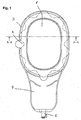
- FIG. 1 shows an embodiment of the invention seen from above.
- the appliance comprises an adhesive wafer (1), here shown with a wave-shaped edge portion, and a coupling flange (2) that may be provided with a lid.
- the wall (3) of the appliance extends into a collecting bag (4) with a valve for removal of effluent.
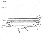
- FIG. 2 shows a cross-section of the embodiment along the A-A line of Figure 1 .
- the appliance comprises and adhesive wafer (1) for securing the appliance to the body part, the wafer (1) is provided with an aperture (5) for receiving the wound, stoma or fistulae (6).
- a wall (3) is extending away from the wafer (1); the wall comprises a rear wall (7) connected to the wafer (1) and a front wall (8) being provided with a coupling flange (2) adapted for coupling and sealing with corresponding coupling means.
- a lid (9) with corresponding coupling means (10) is mounted on the coupling flange (2).
- the rear wall (7) comprises a sealed chamber (11).
- the chamber (11) is shown in inflated position. When the chamber (11) is deflated, the wall (3) may collapse and the appliance will return into a substantially flat configuration.
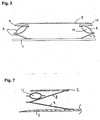
- FIG. 3 is shown an embodiment of the invention wherein the sealed chamber (11) is an integrated part of the front wall (8).
- the position of the sealed chamber is important with regard to the behavior of the appliance. Applied onto flat or slightly curved body parts, the position of the chamber is not as important as if the appliance is applied to curved and protruding body part where it may be subjected to severe stress from twisting and bending.
- Figure 4a and 4b shows an appliance where the sealed chamber (11) constitutes the wall (3) of the application, applied to a curved body part.
- the wall (3) is fully erected by the inflation of the chamber (11), and the configuration of the coupling flange (2) substantially follows the configuration of the adhesive wafer (1), hence the twisting forces are linked.
- the situation demands a strong adhesive of the wafer (1) in order to avoid the twisting forces may bring the adhesive to detach from the skin.
- the coupling flange (2) is also curved and twisted and it may be difficult to apply a lid to the flange (2) in a correct and safe manner.
- the forces of the sealed chamber (11) is transferred directly to the coupling flange (2), making it more difficult to apply the lid, especially if the lid is in the form of a thin and flexible foam flange provided with a transparent film.
- Figure 5a and 5b disclose an embodiment of the invention wherein the chamber (11) is placed outside the wall (3) and right next to the adhesive wafer (1).
- the chamber (11) may share a part of the rear wall (7) or it may be substantially independent of said wall (7).
- the wafer (1) and the coupling flange (2) move more independently of each other's, even though the wafer (1) is curved and twisted, the coupling flange (2) continues to be substantially planar and it may be easy to apply the lid (9).
- the flange (2) may be stiffened by the presence of the inflated chamber (11) and thus more planar in configuration.
- the chamber (11) supports the rear wall (7) to an upright position, while the front wall (8) may accommodate the twisting forces by straightening out in some portions and collapsing in other portions.
- the chamber is placed in connection with the coupling flange or the front wall as the coupling flange may operate more freely in this way and less stress is induced in the adhesive wafer. Attaching the chamber in direct contact with the adhesive wafer may bring the twisting and bending forces to enter the adhesive wafer from the chamber.
- the chamber (11) may be placed next to, but not being a part of, the wall (3), see Figure 6a .
- the chamber (11) When the chamber (11) is inflated it will force the rear wall (7) to rise, while the front wall (8) may absorb the twisting and bending forces by rising more or less around the circumference of the coupling flange.
- Figure 6b is shown a preferred embodiment of the invention wherein the chamber is placed right under the coupling flange, attached to the front wall and the flange, but preferably not being a part thereof.
- the chamber is a part of the front wall.
- the attachment point of the front wall and the chamber to the coupling flange may be anywhere over the skinfacing surface of the coupling flange, but it is preferred that it is at the central portion or towards the periphery of the flange, as this may provide the flange with maximum stability.
- the chamber is in the form of a separate element, e.g. a tube-shaped balloon, which may be placed along the outside of the wall to erect the wall, and be removed when not in use, see Figure 7 .
- the chamber may be attached to the appliance by detachable means (not shown).
- the chamber may comprise a foam.
- Such chamber may not be inflated and deflated as such, however, the foam may be delivered in a compressed state and after decompression expand to full size. If decompressed foam is used, it may be e.g. compressed by vacuum-pack or squeezed in a removable wrapping.
Landscapes
- Health & Medical Sciences (AREA)
- Epidemiology (AREA)
- Nursing (AREA)
- Orthopedic Medicine & Surgery (AREA)
- Engineering & Computer Science (AREA)
- Biomedical Technology (AREA)
- Heart & Thoracic Surgery (AREA)
- Vascular Medicine (AREA)
- Life Sciences & Earth Sciences (AREA)
- Animal Behavior & Ethology (AREA)
- General Health & Medical Sciences (AREA)
- Public Health (AREA)
- Veterinary Medicine (AREA)
- Orthopedics, Nursing, And Contraception (AREA)
- External Artificial Organs (AREA)
Claims (18)
- Appareil d'irrigation et/ou de drainage, ledit appareil comprenanta) un élément côté corps comprenant une plaquette adhésive (1) servant à fixer l'appareil sur la peau du patient, ladite plaquette (1) pouvant être dotée d'une ouverture (5) destinée à recevoir une stomie, entourer une plaie, une fistule ou un site de drainage (6),b) une paroi (3) de matériau souple, la paroi comprenant une paroi arrière (7) et une paroi avant (8), la paroi arrière (7) étant attachée à la plaquette (1) et comportant un orifice configuré pour entourer une surface de la peau d'un patient à irriguer et/ou drainer, et la paroi avant (8) comprenant une bride d'accouplement (2) appropriée pour s'accoupler de manière amovible et former un joint étanche avec des moyens d'accouplement (10) correspondants, la paroi (3) et l'élément côté corps définissant un réservoir, caractérisé en ce que l'appareil comprend en outrec) une chambre hermétique (11), qui est séparée du réservoir, qui, lorsqu'elle est gonflée, établit une distance entre la plaquette adhésive (1) et la bride d'accouplement (2).
- Appareil selon la revendication 1, dans lequel la chambre hermétique (11), lorsqu'elle est gonflée, supporte au moins une des parois (3, 7, 8).
- Appareil selon l'une quelconque des revendications précédentes, dans lequel la chambre hermétique (11), lorsqu'elle est gonflée, supporte la paroi arrière (7).
- Appareil selon l'une quelconque des revendications précédentes, dans lequel la chambre hermétique (11), lorsqu'elle est gonflée, supporte la paroi avant (8).
- Appareil selon l'une quelconque des revendications précédentes, dans lequel la chambre hermétique est munie d'une valve.
- Appareil selon l'une quelconque des revendications précédentes, dans lequel la chambre hermétique (11) constitue une partie de la paroi (3).
- Appareil selon l'une quelconque des revendications précédentes, dans lequel la paroi (3) est dotée d'un orifice.
- Appareil selon l'une quelconque des revendications précédentes, dans lequel la paroi (3) est dotée d'un orifice d'entrée et/ou de sortie.
- Appareil selon l'une quelconque des revendications précédentes, dans lequel la chambre hermétique (11) peut être gonflée et dégonflée pendant l'utilisation de l'appareil.
- Appareil selon l'une quelconque des revendications précédentes, dans lequel la plaquette (1) est dotée d'une ouverture (5) correspondant au contour de la stomie, de la fistule ou de la plaie (6).
- Chambre hermétique (11) destinée à être utilisée avec un appareil d'irrigation et/ou de drainage, ledit appareil comprenanta) un élément côté corps comprenant une plaquette adhésive (1) servant à fixer l'appareil sur la peau du patient, ladite plaquette (1) ou compresse pouvant être appropriée pour recevoir une stomie, entourer une plaie, une fistule ou un site de drainage (6),b) une paroi (3) de matériau souple, la paroi comprenant une paroi arrière (7) étant attachée à la plaquette (1) et comportant un orifice approprié pour entourer la surface de la peau à nettoyer, et une paroi avant (8) étant dotée d'une bride d'accouplement (2), la paroi et l'élément côté corps définissant un réservoir, etc) la chambre hermétique (11) étant séparée du réservoir et pouvant être gonflée en la remplissant d'un fluide, ladite chambre (11), lorsqu'elle est gonflée, établissant une distance entre la plaquette adhésive (1) et la bride d'accouplement (2).
- Chambre hermétique (11) selon la revendication 13, la chambre (11) faisant partie intégrante de l'appareil.
- Chambre hermétique (11) selon la revendication 13, la chambre (11) étant une unité distincte.
- Chambre hermétique (11) selon l'une quelconque des revendications 13 à 15, la chambre (11) encerclant essentiellement la paroi (3) de l'appareil.
- Chambre hermétique (11) selon l'une quelconque des revendications 13 à 16, la chambre (11) étant munie d'une valve.
- Chambre hermétique (11) selon l'une quelconque des revendications 13 à 17, la chambre (11) présentant la forme d'un anneau ouvert.
- Chambre hermétique (11) selon la revendication 18, dans laquelle l'anneau est muni de moyens servant au raccordement des extrémités ouvertes.
- Chambre hermétique (11) selon la revendication 19, dans laquelle les moyens servant au raccordement se présentent sous la forme d'un verrou mécanique, d'un adhésif ou de Velcro.
Applications Claiming Priority (2)
| Application Number | Priority Date | Filing Date | Title |
|---|---|---|---|
| DKPA200500736 | 2005-05-20 | ||
| PCT/DK2006/000274 WO2006122562A2 (fr) | 2005-05-20 | 2006-05-19 | Instrument d'irrigation et/ou drainage |
Publications (2)
| Publication Number | Publication Date |
|---|---|
| EP1885304A2 EP1885304A2 (fr) | 2008-02-13 |
| EP1885304B1 true EP1885304B1 (fr) | 2016-10-12 |
Family
ID=35945166
Family Applications (1)
| Application Number | Title | Priority Date | Filing Date |
|---|---|---|---|
| EP06722951.8A Not-in-force EP1885304B1 (fr) | 2005-05-20 | 2006-05-19 | Instrument d'irrigation et/ou drainage |
Country Status (7)
| Country | Link |
|---|---|
| US (1) | US7976522B2 (fr) |
| EP (1) | EP1885304B1 (fr) |
| JP (1) | JP4705166B2 (fr) |
| CN (1) | CN101180015B (fr) |
| AU (1) | AU2006246837B2 (fr) |
| CA (1) | CA2608228A1 (fr) |
| WO (1) | WO2006122562A2 (fr) |
Families Citing this family (26)
| Publication number | Priority date | Publication date | Assignee | Title |
|---|---|---|---|---|
| AU2007252105A1 (en) * | 2006-05-24 | 2007-11-29 | Coloplast A/S | A kit for collecting stool |
| EP2112914B1 (fr) * | 2007-02-22 | 2018-04-25 | ConvaTec Technologies Inc. | Moyen d'étanchéité pour un dispositif rectal ou d'ostomie |
| EP2241340B1 (fr) * | 2008-01-10 | 2014-07-30 | Alcare Co., Ltd. | Agent adhésif autocollant pour la peau, feuille adhésive autocollante pour la peau et plaque d'appareillage stomique |
| EP2318065B1 (fr) * | 2008-08-05 | 2018-09-26 | Mölnlycke Health Care AB | Composant de fixation solide d'un dispositif médical à la peau |
| US20110190718A1 (en) * | 2008-09-15 | 2011-08-04 | Hollister Incorporated | Ostomy Pouch |
| EP2400937B1 (fr) * | 2009-02-26 | 2013-11-06 | Aslan Ali Pirli | Unité d'assistance pour handicapés physiques |
| US8821464B2 (en) | 2009-07-14 | 2014-09-02 | Stimatix Gi Ltd. | Disposable ostomy assemblies |
| GB2473667B (en) * | 2009-09-22 | 2015-11-18 | Salts Healthcare Ltd | Adhesive member |
| SE534705C2 (sv) * | 2010-03-02 | 2011-11-22 | Moelnlycke Health Care Ab | Stomianordning |
| RU2600198C2 (ru) * | 2010-11-08 | 2016-10-20 | Колопласт А/С | Мешок для стомического использования с промежуточным фильтрующим элементом |
| CN102614574A (zh) * | 2011-01-28 | 2012-08-01 | 谢云春 | 经t管瘘道胆道镜取石隔离引流器 |
| US9107737B2 (en) * | 2011-11-21 | 2015-08-18 | Alan Schwartz | Goggles with facial conforming eyepieces |
| EP2846746B1 (fr) | 2012-05-10 | 2022-03-09 | B.Braun Medical SAS | Dispositif d'ostomie |
| RU2015152523A (ru) | 2013-05-09 | 2017-06-15 | Стиматикс Джи Лтд | Компактный прибор для стомы |
| GB201317667D0 (en) * | 2013-10-07 | 2013-11-20 | Welland Medical Ltd | Support film |
| USD796029S1 (en) * | 2013-12-09 | 2017-08-29 | B. Braun Medical Sas | Colostomy appliance |
| GB201402289D0 (en) * | 2014-02-11 | 2014-03-26 | T G Eakin Ltd | Seal for use with a stoma |
| JP5999801B1 (ja) * | 2014-12-12 | 2016-09-28 | 株式会社フジナミ | 排便袋及び排便袋の製造方法 |
| US11213420B2 (en) * | 2015-10-20 | 2022-01-04 | Coloplast A/S | Coupling system for an ostomy appliance |
| CN105435317B (zh) * | 2015-12-13 | 2018-04-24 | 浙江隆泰医疗科技股份有限公司 | 伤口造瘘引流袋 |
| US10912879B2 (en) * | 2016-10-13 | 2021-02-09 | Drue Maureen Orwig | Collection device for use in irrigation and drainage procedures |
| USD848608S1 (en) | 2016-10-21 | 2019-05-14 | Coloplast A/S | Base unit for anal irrigation and controller |
| US11298257B2 (en) * | 2017-03-22 | 2022-04-12 | 3 West C, Llc. | Ostomy apparatuses and related methods |
| USD1012280S1 (en) | 2018-11-30 | 2024-01-23 | B. Braun Medical Sas | Ostomy device assembly |
| JP7446574B2 (ja) * | 2022-04-21 | 2024-03-11 | 国立大学法人大阪大学 | 洗浄用袋体および洗浄用袋体パッケージ |
| DK4312908T3 (da) | 2022-06-22 | 2024-07-08 | Hollister Inc | Dynamisk, konveks stomibarriere |
Family Cites Families (42)
| Publication number | Priority date | Publication date | Assignee | Title |
|---|---|---|---|---|
| US3123074A (en) * | 1964-03-03 | Colostomy aid | ||
| US2563597A (en) * | 1951-08-07 | Ileostomy surgical device | ||
| US2667167A (en) * | 1951-11-16 | 1954-01-26 | Davol Rubber Co | Colostomy pouch |
| US2662525A (en) * | 1952-07-18 | 1953-12-15 | Anna D Priebe | Sanitary comfort for colostomy pouches |
| US2759477A (en) * | 1953-07-13 | 1956-08-21 | Charles V Mains | Genito-urinary appliances |
| US3253594A (en) * | 1963-07-30 | 1966-05-31 | Frank E Matthews | Peritoneal cannula |
| GB1445092A (en) * | 1972-08-16 | 1976-08-04 | Eakin T G | Surgical drainage appliance |
| US4085752A (en) * | 1976-05-07 | 1978-04-25 | James Canale | Colostomy bag pad |
| IE46487B1 (en) * | 1977-03-31 | 1983-06-29 | Hollister Inc | Improvements relating to drainage pouches |
| US4178915A (en) * | 1977-08-16 | 1979-12-18 | Gerhard Szinicz | Selectively operatable blocking device for tubular body organs |
| US4319571A (en) * | 1979-03-01 | 1982-03-16 | General Motors Corporation | Ostomy appliance |
| US4468227A (en) * | 1981-05-29 | 1984-08-28 | Hollister Incorporated | Wound drainage device with resealable access cap |
| US4586927A (en) * | 1981-08-17 | 1986-05-06 | E. R. Squibb & Sons, Inc. | Irrigation sleeve and attachment therefor |
| US4406659A (en) * | 1981-11-12 | 1983-09-27 | Broida Marna J | Leakage-absorbing supplement to urostomy bag |
| US4419100A (en) * | 1982-03-16 | 1983-12-06 | Hollister Incorporated | Ostomy appliance and faceplate attachment therefor |
| AU572784B2 (en) * | 1982-06-24 | 1988-05-19 | E.R. Squibb & Sons, Inc. | Ostomy bag connection |
| US4778446A (en) * | 1983-07-14 | 1988-10-18 | Squibb & Sons Inc | Wound irrigation and/or drainage device |
| US4596566A (en) * | 1984-10-26 | 1986-06-24 | Kay Dennis M | Ostomy appliance with suction securing chamber |
| AU584962B2 (en) * | 1985-11-21 | 1989-06-08 | Futuraprodukter Hb | Fixing device for stomy bag |
| US4723944A (en) | 1986-06-05 | 1988-02-09 | Jensen Ole R | Fluid collection receptacle with improved non-return valve |
| DE3637355A1 (de) * | 1986-11-03 | 1988-05-11 | Kalwa Artur Dr Med | Colostomieverschluss |
| US4800900A (en) * | 1986-11-04 | 1989-01-31 | Vance Products, Inc. | External strap incontinence control device |
| US4865594A (en) * | 1988-03-18 | 1989-09-12 | Thomas Medical | Absorbent pad for ostomy appliance |
| US4923446A (en) * | 1988-04-14 | 1990-05-08 | Page Mary J | Shield for devices capable of penetrating skin |
| US4850985A (en) * | 1988-08-01 | 1989-07-25 | E. R. Squibb & Sons, Inc. | Ostomy system utilizing a split ring to engage a two element coupling assembly |
| US5203806A (en) * | 1989-08-02 | 1993-04-20 | Marna Broida | Absorbent pad for medical use |
| US5144708A (en) * | 1991-02-26 | 1992-09-08 | Dielectrics Industries | Check valve for fluid bladders |
| SE9101160L (sv) * | 1991-04-18 | 1992-10-19 | Crafcontrol Ab | Anordning vid stomibandage och saett vid anvaendning av anordningen samt foerfarande foer tillverkning av anordningen |
| US5626569A (en) * | 1993-11-08 | 1997-05-06 | B. Braun Biotrol | Device for venting and controlling the pressure inside a stoma collection bag |
| US5582604A (en) * | 1994-05-31 | 1996-12-10 | The Procter & Gamble Company | Disposable absorbent article having a pump and an inflatable component |
| US6110197A (en) | 1994-11-21 | 2000-08-29 | Augustine Medical, Inc. | Flexible non-contact wound treatment device with a single joint |
| US6093160A (en) | 1994-11-21 | 2000-07-25 | Augustine Medical, Inc. | Flexible non-contact wound treatment device |
| FR2731148B1 (fr) * | 1995-03-01 | 1997-08-22 | Braun Biotrol B | Poche de recueil gonflable notamment pour anus artificiel |
| US5672163A (en) * | 1996-04-26 | 1997-09-30 | Bristol-Myers Squibb Company | Ostomy pouch with intervening membrane and superabsorbent |
| US5688236A (en) * | 1996-05-17 | 1997-11-18 | Stephen's Medical, Inc. | Topical hyperbaric device for treating skin disorders |
| US7087041B2 (en) * | 1998-02-25 | 2006-08-08 | Zassi Medical Evolutions, Inc. | Pad for use with continent ostomy port |
| US6458109B1 (en) * | 1998-08-07 | 2002-10-01 | Hill-Rom Services, Inc. | Wound treatment apparatus |
| GB9904527D0 (en) * | 1999-02-26 | 1999-04-21 | Bristol Myers Squibb Co | Ostomy appliance |
| US20030032932A1 (en) * | 2001-08-09 | 2003-02-13 | Stout Cindy Kay | Feeding tube skin guard |
| US6689111B2 (en) * | 2002-03-22 | 2004-02-10 | Bristol-Myers Squibb Company | Controlled evacuation ostomy device with internal seal |
| US20040026438A1 (en) * | 2002-08-12 | 2004-02-12 | Lori Tyra | Article of manufacture with in-molded erasable and markable discrete surface structure and method of manufacture |
| US20070027434A1 (en) * | 2003-06-02 | 2007-02-01 | Ole Pedersen | Adhesive face plate for an ostomy appliance, an ostomy appliance and a method for cleaning a face plate |
-
2006
- 2006-05-19 CN CN200680017518XA patent/CN101180015B/zh not_active Expired - Fee Related
- 2006-05-19 JP JP2008511560A patent/JP4705166B2/ja not_active Expired - Fee Related
- 2006-05-19 EP EP06722951.8A patent/EP1885304B1/fr not_active Not-in-force
- 2006-05-19 US US11/920,739 patent/US7976522B2/en active Active
- 2006-05-19 CA CA002608228A patent/CA2608228A1/fr not_active Abandoned
- 2006-05-19 WO PCT/DK2006/000274 patent/WO2006122562A2/fr not_active Ceased
- 2006-05-19 AU AU2006246837A patent/AU2006246837B2/en not_active Expired - Fee Related
Non-Patent Citations (1)
| Title |
|---|
| None * |
Also Published As
| Publication number | Publication date |
|---|---|
| WO2006122562A3 (fr) | 2007-03-08 |
| CN101180015A (zh) | 2008-05-14 |
| US20100137821A1 (en) | 2010-06-03 |
| CA2608228A1 (fr) | 2006-11-23 |
| CN101180015B (zh) | 2012-05-30 |
| WO2006122562A2 (fr) | 2006-11-23 |
| JP4705166B2 (ja) | 2011-06-22 |
| AU2006246837B2 (en) | 2011-10-06 |
| EP1885304A2 (fr) | 2008-02-13 |
| JP2008539999A (ja) | 2008-11-20 |
| AU2006246837A1 (en) | 2006-11-23 |
| US7976522B2 (en) | 2011-07-12 |
Similar Documents
| Publication | Publication Date | Title |
|---|---|---|
| EP1885304B1 (fr) | Instrument d'irrigation et/ou drainage | |
| JP2008539999A5 (fr) | ||
| EP4029480B1 (fr) | Dispositifs et systèmes de collecte d'urine | |
| US6736803B2 (en) | Urine bag and self-retracting drain tube therefor | |
| US6485476B1 (en) | Continent ostomy port | |
| ES2551122T3 (es) | Bolsa para la recogida de desechos humanos | |
| US20200276045A1 (en) | Temporary stoma evacuation device | |
| JP2006501875A (ja) | 自制式オストミーポートとともに使用するパッド | |
| US20190358390A1 (en) | Device for the repetitive supply and draining of substances for medical therapy, and system and method for producing faecal continence by intermittent colon lavage by means of a permanently placed trans-anal occluding or access catheter | |
| EP0018749A1 (fr) | Appareil collecteur d'urine | |
| CA3069228A1 (fr) | Dispositif poche d'ostomie | |
| WO1999061094A1 (fr) | Chambre a oxygene hyperbare, topique et de taille reglable | |
| AU2003268500B2 (en) | Surgical drape having a fluid collection pouch with an inflatable rim | |
| JP2001218832A (ja) | 尿バッグおよびそれのための自己収縮式ドレインチューブ | |
| US20040045557A1 (en) | Surgical drape having a fluid collection pouch with an inflatable rim | |
| US5741240A (en) | Float tube urinal | |
| CN112754753A (zh) | 一种方便使用的结直肠造瘘分装引流袋 | |
| EP1085924B1 (fr) | Chambre a oxygene hyperbare, topique et de taille reglable | |
| CN214908966U (zh) | 一种方便使用的结直肠造瘘分装引流袋 | |
| CN207804535U (zh) | 一种充气式组合型多功能体位垫 | |
| ES2802574T3 (es) | Producto higiénico | |
| WO2025193539A1 (fr) | Ensembles de collecte de fluide comprenant une ou plusieurs structures tridimensionnelles | |
| AU784678B2 (en) | Continent ostomy port | |
| WO2025085080A1 (fr) | Dispositif de cathéter externe mâle ayant une portion de corps et une portion de poche, et systèmes et procédés d'utilisation associés du dispositif de cathéter | |
| WO2008063160A2 (fr) | Réceptacle d'urine et appareil d'évacuation automatisée de l'urine |
Legal Events
| Date | Code | Title | Description |
|---|---|---|---|
| PUAI | Public reference made under article 153(3) epc to a published international application that has entered the european phase |
Free format text: ORIGINAL CODE: 0009012 |
|
| 17P | Request for examination filed |
Effective date: 20071220 |
|
| AK | Designated contracting states |
Kind code of ref document: A2 Designated state(s): AT BE BG CH CY CZ DE DK EE ES FI FR GB GR HU IE IS IT LI LT LU LV MC NL PL PT RO SE SI SK TR |
|
| 17Q | First examination report despatched |
Effective date: 20080320 |
|
| DAX | Request for extension of the european patent (deleted) | ||
| REG | Reference to a national code |
Ref country code: HK Ref legal event code: DE Ref document number: 1117375 Country of ref document: HK |
|
| REG | Reference to a national code |
Ref country code: HK Ref legal event code: WD Ref document number: 1117375 Country of ref document: HK |
|
| REG | Reference to a national code |
Ref country code: DE Ref legal event code: R079 Ref document number: 602006050551 Country of ref document: DE Free format text: PREVIOUS MAIN CLASS: A61F0005448000 Ipc: A61F0005442000 |
|
| GRAP | Despatch of communication of intention to grant a patent |
Free format text: ORIGINAL CODE: EPIDOSNIGR1 |
|
| RIC1 | Information provided on ipc code assigned before grant |
Ipc: A61F 5/44 20060101ALI20160314BHEP Ipc: A61F 5/442 20060101AFI20160314BHEP |
|
| INTG | Intention to grant announced |
Effective date: 20160406 |
|
| GRAJ | Information related to disapproval of communication of intention to grant by the applicant or resumption of examination proceedings by the epo deleted |
Free format text: ORIGINAL CODE: EPIDOSDIGR1 |
|
| GRAR | Information related to intention to grant a patent recorded |
Free format text: ORIGINAL CODE: EPIDOSNIGR71 |
|
| GRAS | Grant fee paid |
Free format text: ORIGINAL CODE: EPIDOSNIGR3 |
|
| GRAA | (expected) grant |
Free format text: ORIGINAL CODE: 0009210 |
|
| INTC | Intention to grant announced (deleted) | ||
| INTG | Intention to grant announced |
Effective date: 20160901 |
|
| AK | Designated contracting states |
Kind code of ref document: B1 Designated state(s): AT BE BG CH CY CZ DE DK EE ES FI FR GB GR HU IE IS IT LI LT LU LV MC NL PL PT RO SE SI SK TR |
|
| REG | Reference to a national code |
Ref country code: GB Ref legal event code: FG4D |
|
| REG | Reference to a national code |
Ref country code: CH Ref legal event code: EP |
|
| REG | Reference to a national code |
Ref country code: AT Ref legal event code: REF Ref document number: 835783 Country of ref document: AT Kind code of ref document: T Effective date: 20161015 |
|
| REG | Reference to a national code |
Ref country code: IE Ref legal event code: FG4D |
|
| REG | Reference to a national code |
Ref country code: DE Ref legal event code: R096 Ref document number: 602006050551 Country of ref document: DE |
|
| REG | Reference to a national code |
Ref country code: LT Ref legal event code: MG4D |
|
| REG | Reference to a national code |
Ref country code: NL Ref legal event code: MP Effective date: 20161012 |
|
| PG25 | Lapsed in a contracting state [announced via postgrant information from national office to epo] |
Ref country code: LV Free format text: LAPSE BECAUSE OF FAILURE TO SUBMIT A TRANSLATION OF THE DESCRIPTION OR TO PAY THE FEE WITHIN THE PRESCRIBED TIME-LIMIT Effective date: 20161012 |
|
| REG | Reference to a national code |
Ref country code: FR Ref legal event code: PLFP Year of fee payment: 12 |
|
| REG | Reference to a national code |
Ref country code: AT Ref legal event code: MK05 Ref document number: 835783 Country of ref document: AT Kind code of ref document: T Effective date: 20161012 |
|
| PG25 | Lapsed in a contracting state [announced via postgrant information from national office to epo] |
Ref country code: GR Free format text: LAPSE BECAUSE OF FAILURE TO SUBMIT A TRANSLATION OF THE DESCRIPTION OR TO PAY THE FEE WITHIN THE PRESCRIBED TIME-LIMIT Effective date: 20170113 Ref country code: SE Free format text: LAPSE BECAUSE OF FAILURE TO SUBMIT A TRANSLATION OF THE DESCRIPTION OR TO PAY THE FEE WITHIN THE PRESCRIBED TIME-LIMIT Effective date: 20161012 Ref country code: LT Free format text: LAPSE BECAUSE OF FAILURE TO SUBMIT A TRANSLATION OF THE DESCRIPTION OR TO PAY THE FEE WITHIN THE PRESCRIBED TIME-LIMIT Effective date: 20161012 |
|
| PG25 | Lapsed in a contracting state [announced via postgrant information from national office to epo] |
Ref country code: BE Free format text: LAPSE BECAUSE OF FAILURE TO SUBMIT A TRANSLATION OF THE DESCRIPTION OR TO PAY THE FEE WITHIN THE PRESCRIBED TIME-LIMIT Effective date: 20161012 Ref country code: AT Free format text: LAPSE BECAUSE OF FAILURE TO SUBMIT A TRANSLATION OF THE DESCRIPTION OR TO PAY THE FEE WITHIN THE PRESCRIBED TIME-LIMIT Effective date: 20161012 Ref country code: FI Free format text: LAPSE BECAUSE OF FAILURE TO SUBMIT A TRANSLATION OF THE DESCRIPTION OR TO PAY THE FEE WITHIN THE PRESCRIBED TIME-LIMIT Effective date: 20161012 Ref country code: ES Free format text: LAPSE BECAUSE OF FAILURE TO SUBMIT A TRANSLATION OF THE DESCRIPTION OR TO PAY THE FEE WITHIN THE PRESCRIBED TIME-LIMIT Effective date: 20161012 Ref country code: PT Free format text: LAPSE BECAUSE OF FAILURE TO SUBMIT A TRANSLATION OF THE DESCRIPTION OR TO PAY THE FEE WITHIN THE PRESCRIBED TIME-LIMIT Effective date: 20170213 Ref country code: IS Free format text: LAPSE BECAUSE OF FAILURE TO SUBMIT A TRANSLATION OF THE DESCRIPTION OR TO PAY THE FEE WITHIN THE PRESCRIBED TIME-LIMIT Effective date: 20170212 Ref country code: PL Free format text: LAPSE BECAUSE OF FAILURE TO SUBMIT A TRANSLATION OF THE DESCRIPTION OR TO PAY THE FEE WITHIN THE PRESCRIBED TIME-LIMIT Effective date: 20161012 Ref country code: NL Free format text: LAPSE BECAUSE OF FAILURE TO SUBMIT A TRANSLATION OF THE DESCRIPTION OR TO PAY THE FEE WITHIN THE PRESCRIBED TIME-LIMIT Effective date: 20161012 |
|
| REG | Reference to a national code |
Ref country code: DE Ref legal event code: R097 Ref document number: 602006050551 Country of ref document: DE |
|
| PG25 | Lapsed in a contracting state [announced via postgrant information from national office to epo] |
Ref country code: CZ Free format text: LAPSE BECAUSE OF FAILURE TO SUBMIT A TRANSLATION OF THE DESCRIPTION OR TO PAY THE FEE WITHIN THE PRESCRIBED TIME-LIMIT Effective date: 20161012 Ref country code: DK Free format text: LAPSE BECAUSE OF FAILURE TO SUBMIT A TRANSLATION OF THE DESCRIPTION OR TO PAY THE FEE WITHIN THE PRESCRIBED TIME-LIMIT Effective date: 20161012 Ref country code: RO Free format text: LAPSE BECAUSE OF FAILURE TO SUBMIT A TRANSLATION OF THE DESCRIPTION OR TO PAY THE FEE WITHIN THE PRESCRIBED TIME-LIMIT Effective date: 20161012 Ref country code: EE Free format text: LAPSE BECAUSE OF FAILURE TO SUBMIT A TRANSLATION OF THE DESCRIPTION OR TO PAY THE FEE WITHIN THE PRESCRIBED TIME-LIMIT Effective date: 20161012 Ref country code: SK Free format text: LAPSE BECAUSE OF FAILURE TO SUBMIT A TRANSLATION OF THE DESCRIPTION OR TO PAY THE FEE WITHIN THE PRESCRIBED TIME-LIMIT Effective date: 20161012 |
|
| PLBE | No opposition filed within time limit |
Free format text: ORIGINAL CODE: 0009261 |
|
| STAA | Information on the status of an ep patent application or granted ep patent |
Free format text: STATUS: NO OPPOSITION FILED WITHIN TIME LIMIT |
|
| PG25 | Lapsed in a contracting state [announced via postgrant information from national office to epo] |
Ref country code: IT Free format text: LAPSE BECAUSE OF FAILURE TO SUBMIT A TRANSLATION OF THE DESCRIPTION OR TO PAY THE FEE WITHIN THE PRESCRIBED TIME-LIMIT Effective date: 20161012 Ref country code: LU Free format text: LAPSE BECAUSE OF NON-PAYMENT OF DUE FEES Effective date: 20170531 Ref country code: BG Free format text: LAPSE BECAUSE OF FAILURE TO SUBMIT A TRANSLATION OF THE DESCRIPTION OR TO PAY THE FEE WITHIN THE PRESCRIBED TIME-LIMIT Effective date: 20170112 |
|
| 26N | No opposition filed |
Effective date: 20170713 |
|
| PG25 | Lapsed in a contracting state [announced via postgrant information from national office to epo] |
Ref country code: SI Free format text: LAPSE BECAUSE OF FAILURE TO SUBMIT A TRANSLATION OF THE DESCRIPTION OR TO PAY THE FEE WITHIN THE PRESCRIBED TIME-LIMIT Effective date: 20161012 |
|
| REG | Reference to a national code |
Ref country code: CH Ref legal event code: PL |
|
| PG25 | Lapsed in a contracting state [announced via postgrant information from national office to epo] |
Ref country code: MC Free format text: LAPSE BECAUSE OF FAILURE TO SUBMIT A TRANSLATION OF THE DESCRIPTION OR TO PAY THE FEE WITHIN THE PRESCRIBED TIME-LIMIT Effective date: 20161012 |
|
| REG | Reference to a national code |
Ref country code: IE Ref legal event code: MM4A |
|
| PG25 | Lapsed in a contracting state [announced via postgrant information from national office to epo] |
Ref country code: CH Free format text: LAPSE BECAUSE OF NON-PAYMENT OF DUE FEES Effective date: 20170531 Ref country code: LI Free format text: LAPSE BECAUSE OF NON-PAYMENT OF DUE FEES Effective date: 20170531 |
|
| REG | Reference to a national code |
Ref country code: FR Ref legal event code: PLFP Year of fee payment: 13 |
|
| PG25 | Lapsed in a contracting state [announced via postgrant information from national office to epo] |
Ref country code: LU Free format text: LAPSE BECAUSE OF NON-PAYMENT OF DUE FEES Effective date: 20170519 |
|
| PG25 | Lapsed in a contracting state [announced via postgrant information from national office to epo] |
Ref country code: IE Free format text: LAPSE BECAUSE OF NON-PAYMENT OF DUE FEES Effective date: 20170519 |
|
| PG25 | Lapsed in a contracting state [announced via postgrant information from national office to epo] |
Ref country code: HU Free format text: LAPSE BECAUSE OF FAILURE TO SUBMIT A TRANSLATION OF THE DESCRIPTION OR TO PAY THE FEE WITHIN THE PRESCRIBED TIME-LIMIT; INVALID AB INITIO Effective date: 20060519 |
|
| PG25 | Lapsed in a contracting state [announced via postgrant information from national office to epo] |
Ref country code: CY Free format text: LAPSE BECAUSE OF NON-PAYMENT OF DUE FEES Effective date: 20161012 |
|
| PG25 | Lapsed in a contracting state [announced via postgrant information from national office to epo] |
Ref country code: TR Free format text: LAPSE BECAUSE OF FAILURE TO SUBMIT A TRANSLATION OF THE DESCRIPTION OR TO PAY THE FEE WITHIN THE PRESCRIBED TIME-LIMIT Effective date: 20161012 |
|
| PGFP | Annual fee paid to national office [announced via postgrant information from national office to epo] |
Ref country code: FR Payment date: 20230525 Year of fee payment: 18 Ref country code: DE Payment date: 20230530 Year of fee payment: 18 |
|
| PGFP | Annual fee paid to national office [announced via postgrant information from national office to epo] |
Ref country code: GB Payment date: 20230529 Year of fee payment: 18 |
|
| REG | Reference to a national code |
Ref country code: DE Ref legal event code: R119 Ref document number: 602006050551 Country of ref document: DE |
|
| GBPC | Gb: european patent ceased through non-payment of renewal fee |
Effective date: 20240519 |
|
| PG25 | Lapsed in a contracting state [announced via postgrant information from national office to epo] |
Ref country code: DE Free format text: LAPSE BECAUSE OF NON-PAYMENT OF DUE FEES Effective date: 20241203 |
|
| PG25 | Lapsed in a contracting state [announced via postgrant information from national office to epo] |
Ref country code: FR Free format text: LAPSE BECAUSE OF NON-PAYMENT OF DUE FEES Effective date: 20240531 |
|
| PG25 | Lapsed in a contracting state [announced via postgrant information from national office to epo] |
Ref country code: GB Free format text: LAPSE BECAUSE OF NON-PAYMENT OF DUE FEES Effective date: 20240519 |