EP1886015B1 - Vorrichtung zur energieerzeugung mit einer wasserturbine mit bisymmetrischer schaufel - Google Patents
Vorrichtung zur energieerzeugung mit einer wasserturbine mit bisymmetrischer schaufel Download PDFInfo
- Publication number
- EP1886015B1 EP1886015B1 EP06743936A EP06743936A EP1886015B1 EP 1886015 B1 EP1886015 B1 EP 1886015B1 EP 06743936 A EP06743936 A EP 06743936A EP 06743936 A EP06743936 A EP 06743936A EP 1886015 B1 EP1886015 B1 EP 1886015B1
- Authority
- EP
- European Patent Office
- Prior art keywords
- power generation
- generation apparatus
- turbine
- blade
- aerofoil
- Prior art date
- Legal status (The legal status is an assumption and is not a legal conclusion. Google has not performed a legal analysis and makes no representation as to the accuracy of the status listed.)
- Expired - Lifetime
Links
Images



Classifications
-
- F—MECHANICAL ENGINEERING; LIGHTING; HEATING; WEAPONS; BLASTING
- F03—MACHINES OR ENGINES FOR LIQUIDS; WIND, SPRING, OR WEIGHT MOTORS; PRODUCING MECHANICAL POWER OR A REACTIVE PROPULSIVE THRUST, NOT OTHERWISE PROVIDED FOR
- F03B—MACHINES OR ENGINES FOR LIQUIDS
- F03B13/00—Adaptations of machines or engines for special use; Combinations of machines or engines with driving or driven apparatus; Power stations or aggregates
- F03B13/12—Adaptations of machines or engines for special use; Combinations of machines or engines with driving or driven apparatus; Power stations or aggregates characterised by using wave or tide energy
- F03B13/26—Adaptations of machines or engines for special use; Combinations of machines or engines with driving or driven apparatus; Power stations or aggregates characterised by using wave or tide energy using tide energy
-
- F—MECHANICAL ENGINEERING; LIGHTING; HEATING; WEAPONS; BLASTING
- F01—MACHINES OR ENGINES IN GENERAL; ENGINE PLANTS IN GENERAL; STEAM ENGINES
- F01D—NON-POSITIVE DISPLACEMENT MACHINES OR ENGINES, e.g. STEAM TURBINES
- F01D5/00—Blades; Blade-carrying members; Heating, heat-insulating, cooling or antivibration means on the blades or the members
- F01D5/12—Blades
- F01D5/14—Form or construction
- F01D5/141—Shape, i.e. outer, aerodynamic form
-
- F—MECHANICAL ENGINEERING; LIGHTING; HEATING; WEAPONS; BLASTING
- F01—MACHINES OR ENGINES IN GENERAL; ENGINE PLANTS IN GENERAL; STEAM ENGINES
- F01D—NON-POSITIVE DISPLACEMENT MACHINES OR ENGINES, e.g. STEAM TURBINES
- F01D5/00—Blades; Blade-carrying members; Heating, heat-insulating, cooling or antivibration means on the blades or the members
- F01D5/12—Blades
- F01D5/14—Form or construction
-
- F—MECHANICAL ENGINEERING; LIGHTING; HEATING; WEAPONS; BLASTING
- F03—MACHINES OR ENGINES FOR LIQUIDS; WIND, SPRING, OR WEIGHT MOTORS; PRODUCING MECHANICAL POWER OR A REACTIVE PROPULSIVE THRUST, NOT OTHERWISE PROVIDED FOR
- F03B—MACHINES OR ENGINES FOR LIQUIDS
- F03B13/00—Adaptations of machines or engines for special use; Combinations of machines or engines with driving or driven apparatus; Power stations or aggregates
- F03B13/12—Adaptations of machines or engines for special use; Combinations of machines or engines with driving or driven apparatus; Power stations or aggregates characterised by using wave or tide energy
- F03B13/26—Adaptations of machines or engines for special use; Combinations of machines or engines with driving or driven apparatus; Power stations or aggregates characterised by using wave or tide energy using tide energy
- F03B13/264—Adaptations of machines or engines for special use; Combinations of machines or engines with driving or driven apparatus; Power stations or aggregates characterised by using wave or tide energy using tide energy using the horizontal flow of water resulting from tide movement
-
- F—MECHANICAL ENGINEERING; LIGHTING; HEATING; WEAPONS; BLASTING
- F03—MACHINES OR ENGINES FOR LIQUIDS; WIND, SPRING, OR WEIGHT MOTORS; PRODUCING MECHANICAL POWER OR A REACTIVE PROPULSIVE THRUST, NOT OTHERWISE PROVIDED FOR
- F03B—MACHINES OR ENGINES FOR LIQUIDS
- F03B17/00—Other machines or engines
- F03B17/06—Other machines or engines using liquid flow with predominantly kinetic energy conversion, e.g. of swinging-flap type, "run-of-river", "ultra-low head"
-
- F—MECHANICAL ENGINEERING; LIGHTING; HEATING; WEAPONS; BLASTING
- F03—MACHINES OR ENGINES FOR LIQUIDS; WIND, SPRING, OR WEIGHT MOTORS; PRODUCING MECHANICAL POWER OR A REACTIVE PROPULSIVE THRUST, NOT OTHERWISE PROVIDED FOR
- F03B—MACHINES OR ENGINES FOR LIQUIDS
- F03B17/00—Other machines or engines
- F03B17/06—Other machines or engines using liquid flow with predominantly kinetic energy conversion, e.g. of swinging-flap type, "run-of-river", "ultra-low head"
- F03B17/061—Other machines or engines using liquid flow with predominantly kinetic energy conversion, e.g. of swinging-flap type, "run-of-river", "ultra-low head" with rotation axis substantially in flow direction
-
- F—MECHANICAL ENGINEERING; LIGHTING; HEATING; WEAPONS; BLASTING
- F03—MACHINES OR ENGINES FOR LIQUIDS; WIND, SPRING, OR WEIGHT MOTORS; PRODUCING MECHANICAL POWER OR A REACTIVE PROPULSIVE THRUST, NOT OTHERWISE PROVIDED FOR
- F03B—MACHINES OR ENGINES FOR LIQUIDS
- F03B3/00—Machines or engines of reaction type; Parts or details peculiar thereto
- F03B3/12—Blades; Blade-carrying rotors
-
- F—MECHANICAL ENGINEERING; LIGHTING; HEATING; WEAPONS; BLASTING
- F03—MACHINES OR ENGINES FOR LIQUIDS; WIND, SPRING, OR WEIGHT MOTORS; PRODUCING MECHANICAL POWER OR A REACTIVE PROPULSIVE THRUST, NOT OTHERWISE PROVIDED FOR
- F03B—MACHINES OR ENGINES FOR LIQUIDS
- F03B3/00—Machines or engines of reaction type; Parts or details peculiar thereto
- F03B3/12—Blades; Blade-carrying rotors
- F03B3/121—Blades, their form or construction
-
- F—MECHANICAL ENGINEERING; LIGHTING; HEATING; WEAPONS; BLASTING
- F04—POSITIVE - DISPLACEMENT MACHINES FOR LIQUIDS; PUMPS FOR LIQUIDS OR ELASTIC FLUIDS
- F04D—NON-POSITIVE-DISPLACEMENT PUMPS
- F04D29/00—Details, component parts, or accessories
- F04D29/18—Rotors
- F04D29/181—Axial flow rotors
-
- F—MECHANICAL ENGINEERING; LIGHTING; HEATING; WEAPONS; BLASTING
- F05—INDEXING SCHEMES RELATING TO ENGINES OR PUMPS IN VARIOUS SUBCLASSES OF CLASSES F01-F04
- F05B—INDEXING SCHEME RELATING TO WIND, SPRING, WEIGHT, INERTIA OR LIKE MOTORS, TO MACHINES OR ENGINES FOR LIQUIDS COVERED BY SUBCLASSES F03B, F03D AND F03G
- F05B2210/00—Working fluid
- F05B2210/40—Flow geometry or direction
- F05B2210/404—Flow geometry or direction bidirectional, i.e. in opposite, alternating directions
-
- F—MECHANICAL ENGINEERING; LIGHTING; HEATING; WEAPONS; BLASTING
- F05—INDEXING SCHEMES RELATING TO ENGINES OR PUMPS IN VARIOUS SUBCLASSES OF CLASSES F01-F04
- F05B—INDEXING SCHEME RELATING TO WIND, SPRING, WEIGHT, INERTIA OR LIKE MOTORS, TO MACHINES OR ENGINES FOR LIQUIDS COVERED BY SUBCLASSES F03B, F03D AND F03G
- F05B2240/00—Components
- F05B2240/10—Stators
- F05B2240/13—Stators to collect or cause flow towards or away from turbines
-
- F—MECHANICAL ENGINEERING; LIGHTING; HEATING; WEAPONS; BLASTING
- F05—INDEXING SCHEMES RELATING TO ENGINES OR PUMPS IN VARIOUS SUBCLASSES OF CLASSES F01-F04
- F05B—INDEXING SCHEME RELATING TO WIND, SPRING, WEIGHT, INERTIA OR LIKE MOTORS, TO MACHINES OR ENGINES FOR LIQUIDS COVERED BY SUBCLASSES F03B, F03D AND F03G
- F05B2240/00—Components
- F05B2240/10—Stators
- F05B2240/13—Stators to collect or cause flow towards or away from turbines
- F05B2240/133—Stators to collect or cause flow towards or away from turbines with a convergent-divergent guiding structure, e.g. a Venturi conduit
-
- F—MECHANICAL ENGINEERING; LIGHTING; HEATING; WEAPONS; BLASTING
- F05—INDEXING SCHEMES RELATING TO ENGINES OR PUMPS IN VARIOUS SUBCLASSES OF CLASSES F01-F04
- F05B—INDEXING SCHEME RELATING TO WIND, SPRING, WEIGHT, INERTIA OR LIKE MOTORS, TO MACHINES OR ENGINES FOR LIQUIDS COVERED BY SUBCLASSES F03B, F03D AND F03G
- F05B2240/00—Components
- F05B2240/20—Rotors
- F05B2240/30—Characteristics of rotor blades, i.e. of any element transforming dynamic fluid energy to or from rotational energy and being attached to a rotor
- F05B2240/301—Cross-section characteristics
-
- F—MECHANICAL ENGINEERING; LIGHTING; HEATING; WEAPONS; BLASTING
- F05—INDEXING SCHEMES RELATING TO ENGINES OR PUMPS IN VARIOUS SUBCLASSES OF CLASSES F01-F04
- F05B—INDEXING SCHEME RELATING TO WIND, SPRING, WEIGHT, INERTIA OR LIKE MOTORS, TO MACHINES OR ENGINES FOR LIQUIDS COVERED BY SUBCLASSES F03B, F03D AND F03G
- F05B2240/00—Components
- F05B2240/40—Use of a multiplicity of similar components
-
- F—MECHANICAL ENGINEERING; LIGHTING; HEATING; WEAPONS; BLASTING
- F05—INDEXING SCHEMES RELATING TO ENGINES OR PUMPS IN VARIOUS SUBCLASSES OF CLASSES F01-F04
- F05D—INDEXING SCHEME FOR ASPECTS RELATING TO NON-POSITIVE-DISPLACEMENT MACHINES OR ENGINES, GAS-TURBINES OR JET-PROPULSION PLANTS
- F05D2210/00—Working fluids
- F05D2210/40—Flow geometry or direction
- F05D2210/44—Flow geometry or direction bidirectional, i.e. in opposite, alternating directions
-
- F—MECHANICAL ENGINEERING; LIGHTING; HEATING; WEAPONS; BLASTING
- F05—INDEXING SCHEMES RELATING TO ENGINES OR PUMPS IN VARIOUS SUBCLASSES OF CLASSES F01-F04
- F05D—INDEXING SCHEME FOR ASPECTS RELATING TO NON-POSITIVE-DISPLACEMENT MACHINES OR ENGINES, GAS-TURBINES OR JET-PROPULSION PLANTS
- F05D2240/00—Components
- F05D2240/20—Rotors
- F05D2240/30—Characteristics of rotor blades, i.e. of any element transforming dynamic fluid energy to or from rotational energy and being attached to a rotor
- F05D2240/301—Cross-sectional characteristics
-
- F—MECHANICAL ENGINEERING; LIGHTING; HEATING; WEAPONS; BLASTING
- F05—INDEXING SCHEMES RELATING TO ENGINES OR PUMPS IN VARIOUS SUBCLASSES OF CLASSES F01-F04
- F05D—INDEXING SCHEME FOR ASPECTS RELATING TO NON-POSITIVE-DISPLACEMENT MACHINES OR ENGINES, GAS-TURBINES OR JET-PROPULSION PLANTS
- F05D2240/00—Components
- F05D2240/40—Use of a multiplicity of similar components
-
- F—MECHANICAL ENGINEERING; LIGHTING; HEATING; WEAPONS; BLASTING
- F05—INDEXING SCHEMES RELATING TO ENGINES OR PUMPS IN VARIOUS SUBCLASSES OF CLASSES F01-F04
- F05D—INDEXING SCHEME FOR ASPECTS RELATING TO NON-POSITIVE-DISPLACEMENT MACHINES OR ENGINES, GAS-TURBINES OR JET-PROPULSION PLANTS
- F05D2250/00—Geometry
- F05D2250/70—Shape
- F05D2250/74—Shape given by a set or table of xyz-coordinates
-
- Y—GENERAL TAGGING OF NEW TECHNOLOGICAL DEVELOPMENTS; GENERAL TAGGING OF CROSS-SECTIONAL TECHNOLOGIES SPANNING OVER SEVERAL SECTIONS OF THE IPC; TECHNICAL SUBJECTS COVERED BY FORMER USPC CROSS-REFERENCE ART COLLECTIONS [XRACs] AND DIGESTS
- Y02—TECHNOLOGIES OR APPLICATIONS FOR MITIGATION OR ADAPTATION AGAINST CLIMATE CHANGE
- Y02E—REDUCTION OF GREENHOUSE GAS [GHG] EMISSIONS, RELATED TO ENERGY GENERATION, TRANSMISSION OR DISTRIBUTION
- Y02E10/00—Energy generation through renewable energy sources
- Y02E10/20—Hydro energy
-
- Y—GENERAL TAGGING OF NEW TECHNOLOGICAL DEVELOPMENTS; GENERAL TAGGING OF CROSS-SECTIONAL TECHNOLOGIES SPANNING OVER SEVERAL SECTIONS OF THE IPC; TECHNICAL SUBJECTS COVERED BY FORMER USPC CROSS-REFERENCE ART COLLECTIONS [XRACs] AND DIGESTS
- Y02—TECHNOLOGIES OR APPLICATIONS FOR MITIGATION OR ADAPTATION AGAINST CLIMATE CHANGE
- Y02E—REDUCTION OF GREENHOUSE GAS [GHG] EMISSIONS, RELATED TO ENERGY GENERATION, TRANSMISSION OR DISTRIBUTION
- Y02E10/00—Energy generation through renewable energy sources
- Y02E10/30—Energy from the sea, e.g. using wave energy or salinity gradient
-
- Y—GENERAL TAGGING OF NEW TECHNOLOGICAL DEVELOPMENTS; GENERAL TAGGING OF CROSS-SECTIONAL TECHNOLOGIES SPANNING OVER SEVERAL SECTIONS OF THE IPC; TECHNICAL SUBJECTS COVERED BY FORMER USPC CROSS-REFERENCE ART COLLECTIONS [XRACs] AND DIGESTS
- Y02—TECHNOLOGIES OR APPLICATIONS FOR MITIGATION OR ADAPTATION AGAINST CLIMATE CHANGE
- Y02T—CLIMATE CHANGE MITIGATION TECHNOLOGIES RELATED TO TRANSPORTATION
- Y02T50/00—Aeronautics or air transport
- Y02T50/60—Efficient propulsion technologies, e.g. for aircraft
Definitions
- the present invention relates to a power generation apparatus as defined in the preamble of claim 1
- Such an apparatus is known eg from WO 03/029645 .
- Underwater power generators e.g. for generating electrical power, and associated turbine units are known.
- WO 03/029645 A1 discloses a power generator, such as an electrical power generator, comprising at least one underwater turbine unit including a housing having a liquid flow channel therethrough and at least one turbine means mounted in the flow channel for rotation in response to liquid flow through the channel.
- the turbine unit also comprises a pump means operatively coupled to the turbine means.
- the turbine unit provides a turbine unit part releasably mountable in the turbine unit, the part including at least one of the at least one turbine means and the pump means.
- the turbine unit part also comprises at least part of the flow channel.
- CH-A-316900 describes a power generation apparatus with an underwater turbine having blades which are of a bi-symmetrical shape.
- Known tidal or current electrical power generators seek to address a need for increasing energy requirements in an environmentally friendly way.
- known generators suffer from a number of problems, e.g. relatively low efficiency of conversion of tidal and/or current flow to electrical energy.
- symmetrical aerofoils are known, and are employed for the stabilising surfaces of aircraft, such as the fin and tailplane, and also for wings of highly aerobatic aircraft which require the "lift” force to be high in both positive and negative directions.
- These aerofoils have zero “camber” or, in other words, a straight mean line which is clothed with a streamline form symmetrical about the mean line.
- Such a streamline form is asymmetrical fore and aft, with a blunt leading edge and a sharp trailing edge.
- This form has also been used for ships hulls. Conventionally, the leading edge or "entry” has been easier to design than the rearward curves or "run” of a ship's hull.
- a power generation apparatus according to claim 1.
- the aerofoil of the blade is symmetrical about a mid-chord line thereof.
- mid-chord line is meant a line extending heightwise or breadthwise from substantially half way along a chord of the aerofoil.
- the aerofoil is symmetrical about a chord thereof.
- Such an aerofoil may therefore be said to be bi-symmetrical.
- the aerofoil comprises first and second leading edges.
- each leading edge is part circular in shape.
- chord of the aerofoil comprises a straight line.
- a camber of the aerofoil is zero, and a camber line comprises a straight line.
- the mid-chord line is substantially perpendicular to the chord.
- a height of the aerofoil is greatest at or around the mid-chord line, reducing towards either end.
- a ratio of mid-chord line height or thickness to chord length is around 5% to 25%, most preferably 12% to 20%, and advantageously substantially 15%.
- a position of maximum height or thickness of the aerofoil is substantially at the mid-chord line, i.e. 50% along the chord.
- An advantageous implementation of the present invention provides a bi-symmetrical aerofoil with zero camber and maximum height or thickness at mid-chord.
- the aerofoil shape comprises a NACA 67, particularly a NACA 67 1 -015, leading edge shape reflected about a mid-chord line.
- a method of generating power according to claim 38 comprising at least an apparatus according to the first aspect of the present invention.
- the blade comprises a plurality of aerofoils (or design sections, e.g. longitudinally spaced sections) according to the first aspect of the present invention, for example, in the range of 3 to 9, and preferably 5.
- a taper ratio i.e. tip chord to hub chord ratio
- a taper ratio may be in the range 0.3 to 0.8, and preferably around 0.5.
- an aspect ratio i.e. mean chord to blade height ratio
- the hub setting angle of the aerofoils are in the range 30° to 60° from an axial direction, and preferably around 45° or 48°.
- the tip setting angle is in the range 70° to 85° from an axial direction, and preferably around 79°.
- a blade chord length at mid height may be in the range 0.3m to 3.0m, and preferably around 1.0m.
- the turbine may comprise a plurality of blades, e.g. in the range 2 to 9 blades, preferably 3 to 7 blades, in advantageous implementations 5 or 7 blades.
- a ratio of hub diameter to tip diameter may be in the range of 0.1 to 0.5, and preferably around 0.2.
- a tip diameter may be in the range 5m to 30m, and preferably around 15m to 20m.
- the turbine may be adapted to rotate, in use, at a rate of 10 rpm to 50 rpm, and preferably around 25 rpm.
- the turbine unit includes a housing having a fluid or liquid flow channel therethrough and the at least one turbine according to the present invention is mounted in the flow channel for rotation in response to liquid flow through the flow channel.
- the flow channel may comprise a venturi, e.g. a convergent-divergent venturi, tapering from openings at either end of the flow channel towards an inner part of the flow channel.
- This arrangement may, in use, provide a zone of acceleration for fluid flow through the flow channel.
- the housing may be substantially symmetrical about a mid-point location thereof, and the at least one turbine may be located substantially thereat.
- the liquid may be provided from a body of water within which the turbine unit is submerged.
- the turbine housing may comprise an inner housing sleeve, and optionally an outer housing sleeve, which inner sleeve defines the flow channel.
- the housing may be secured to an underwater surface by a mounting structure and may be substantially aligned with a direction of tidal (tidal stream) or current flow.
- An angle between an axial direction of the housing and a direction of tidal or current flow may be around 0° to 45°, and preferably between 0 to 22°, and beneficially around 0°.
- the turbine unit may provide a part releasably mountable in the turbine unit.
- the part may include at least one of the turbine and the pump means.
- the turbine unit part may include at least a part of the housing, e.g. at least part of the flow channel, which may comprise at least part of the inner housing sleeve.
- the turbine unit may be driven, i.e. the turbine may be caused to rotate, in use, in response to fluid (e.g. tidal and/or current) flow in either direction through the flow channel.
- fluid e.g. tidal and/or current
- the turbine unit may work in both ebb and flood tides.
- the turbine may rotate in a first direction of rotation in a first direction of tidal flow, and the turbine may rotate in a second, opposite, direction of rotation in a second, opposite direction of tidal flow.
- an inlet and/or outlet (exit) diameter of the flow channel or duct may be in the range 7m to 40m, and preferably around 20m.
- a length of the flow channel or duct may be in the range 7m to 50m, and preferably around 28m.
- the power generation apparatus comprises an electrical power generator.
- the power generation apparatus may further comprise:
- the fluid may comprise the liquid.
- the power generation apparatus may be adapted to produce electrical power as alternating current/voltage (AC) or direct current/voltage (DC).
- AC alternating current/voltage
- DC direct current/voltage
- the at least one turbine unit is located on, near, or above a sea bed, ocean floor, river bed or the like.
- the fluid flow may comprise tidal flow, e.g. of ebb and/or flood tides, tidal stream flow, or current flow.
- tidal flow e.g. of ebb and/or flood tides, tidal stream flow, or current flow.
- the at least one turbine rotates in one direction in response to fluid flow in one direction and the at least one turbine rotates in another or counter direction in response to fluid flow in another direction.
- the one direction and the another direction of fluid may be at least partly opposite in direction, and may be substantially opposed in direction, e.g. the one direction may be a direction of an ebb tide flow and the another direction may be a direction of a flood tide flow.
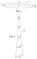
- FIG. 5 there is shown an aerofoil, generally designated 5, according to an embodiment of the present invention.
- the aerofoil 5 is symmetrical about a mid-chord line A thereof.
- mid-chord line A is meant a line extending height wise (or width wise) from substantially half way along a chord B of the aerofoil 5.
- the aerofoil 5 is also symmetrical about the chord B.
- the aerofoil 5 may therefore be said to be "bisymmetrical”.
- the aerofoil 5 comprises first and second leading edges 10, 15, each leading edge 10, 15 being part circular in shape.
- the chord B of the aerofoil 5 comprises a straight line.
- a camber of the aerofoil 5 is zero, and a camber line comprises a straight line.
- the mid-chord line A can be seen to be perpendicular to the chord B.
- a height of the aerofoil 5 is greatest at or around the mid-chord line A, reducing towards either end, that is, towards each leading edge 10,15.
- a ratio of mid- chord line height or thickness to chord length is typically around 5% to 25%, more typically between 12% and 20%, and in this embodiment around 15%.
- the position of maximum height or thickness of the aerofoil 5 is substantially at the mid-chord line A, i.e. around 50% of the way along the chord B.
- the present embodiment of the aerofoil 5 therefore provides a bisymmetrical aerofoil 5 with zero camber and maximum height or thickness at mid- chord.
- the shape of the aerofoil 5 in a preferred implementation of this embodiment comprises a NACA 67 series profile, particularly a NACA 67 1 -015, leading edge shape reflected about a mid-chord line.
- the blade 20 comprising at least one aerofoil 5.
- the blade 20 comprises a plurality of aerofoils (or longitudinal spaced design sections) 5a to 5e, for example, in the range of 3 to 9 design sections, and preferably as shown in Figure 2 , 5 design sections.
- a taper ratio, i.e. tip chord to hub chord ratio can be in the range of 0.2 to 0.8, and in this embodiment around 0.5.
- An aspect ratio, i.e. mean chord to blade height ratio can be in the range of 3 to 10, and in this embodiment around 5.
- a hub setting or stagger angle can be in the range of 30° to 60° from axial direction, and in this embodiment around 45° or 48°.
- a tip setting or stagger angle can be in the range of 70° to 85° from an axial direction, and in this embodiment around 79°. It will therefore be appreciated that between hub and tip the blade 20 is typically twisted.
- a blade chord length at mid-height can be in the range of 0.3 metres to 3 metres, and in this embodiment around 1 metre.
- a turbine generally designated 25, comprising at least one blade 20.
- the turbine 25 comprises a plurality of blades 20a to 20e, for example, in the range 2 to 9 blades and typically in the range 3 to 7 blades, and in this advantageous implementation, 5 blades - although in an alternative advantageous implementation, 7 blades may be provided.
- the turbine 25 comprises a hub structure 30 upon which is mounted a rotating hub 35 from which the blades 20a to 20e outwardly and radially extend.
- a ratio of hub diameter to tip diameter is in the range 0.1 to 0.5, and in this embodiment around 0.2.
- a tip diameter is in the range 5 metres to 30 metres, and in this embodiment around 15 metres.
- the turbine 25 is adapted to rotate in use at a rate of around 10 rpm to 50 rpm, and in this embodiment at around 25 rpm.
- the turbine unit 30 includes a housing or duct 35 having a liquid or fluid flow channel 40 therethrough and at least one turbine 25 mounted in the flow channel 40 for rotation in response to liquid/fluid (water) flow through the flow channel 40.
- the flow channel 40 defines a flow restriction which comprises a venturi comprising a convergent-divergent venturi, tapering from openings 45,50 at either end of the flow channel 40 towards an inner part 55 of the flow channel 40.
- the housing 35 is substantially symmetrical about a mid-point location 55 and the turbine 25 is located substantially at the mid-point location 55 within the flow channel 40.
- the turbine unit 30 also includes a support structure for supporting the turbine unit 30 upon a seabed, ocean floor, riverbed, or the like, which support structure is not shown in Figure 4 .
- the liquid for driving the turbine 25 is provided from a body of water within which the turbine unit 30 is submerged - e.g. sea water.
- the housing or duct 35 comprises a single sleeve.
- the housing or duct 35 has a narrowed or reduced waist on an outer surface thereof between ends thereof, and in this case, substantially mid-way between the ends thereof.
- the turbine housing 35 can comprise an outer housing sleeve and an inner housing sleeve which inner sleeve defines the flow channel 40.
- the housing 35 can be secured to an underwater surface by a support or mounting structure (not shown) and substantially aligned to a direction of predicted tidal or current flow.
- the angle between the actual direction of the housing 35 and the direction of tidal or current flow can be between 0° to 45°, and in this embodiment typically around 0°.
- An inlet and/or outlet diameter of the flow channel 40 can be in the range 7 metres to 40 metres, and in this embodiment typically around 20 metres.
- the length of the flow channel 40 or duct can be in the range 7 metres to 50 metres, and typically in this embodiment around 28 metres.
- the turbine unit 30 also includes support struts 41 for supporting the turbine 25 within the duct 35.
- the stationary hub 30 comprises a nose cone 42 and tail cone 43.
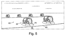
- a power generation apparatus comprising a plurality of turbine units 30 operatively linked or connected by electrical cable 65.
- Each of the turbine units 30 includes a supporting structure 70 for locating the respective turbine unit 30 on seabed 75.
- the power generation apparatus 60 comprises in the embodiment an electrical power generator.
- the power generation apparatus 60 comprises within each turbine unit 30: a pump means operatively coupled to the at least one turbine 25; a generator means (not shown) driven by the turbine 25 and optionally located separately from the at least one turbine unit 30; and a fluid supply means coupling the pump to the generator means for supplying fluid from the pump means to the generator means for generating power.
- the fluid optionally and advantageously comprises the liquid within which the turbine units 30 are submerged.
- the power generation apparatus 60 can be adapted to produce electrical power as alternating current (AC) or direct current (DC).
- the generation apparatus 60 is employed in a method of generating power.
- the method comprises the steps of:
- the at least one turbine unit 30 is located on a seabed, ocean floor, river bed or the like as can be seen from Figure 5 .
- the fluid flow comprises tidal flow or stream, e.g. ebb and/or flow tides or alternatively current flow.
- the at least one turbine 25 rotates in one direction in response to fluid flow in one direction and in another or counter direction in response to fluid flow in another direction.
- the one direction and another direction of fluid flow can be at least partly opposite in direction and may be substantially opposite in direction, e.g. one direction may be a direction of an ebb tide flow and the other direction may be the direction of a flood tide flow.
- the maximum thickness is located at the mid-point of the aerofoil 5 at 50% chord, which makes it a very unusual aerofoil 5 for low speed applications.
- the leading edge geometry is not arbitrary. Calculations using an Eppler aerofoil design and analysis program showed that a simple stretched ellipse would likely not be satisfactory, even when the leading edges were enlarged. Eppler R, "Aerofoil Design and Data" Springer, 1991.
- a standard aerofoil leading edge can be selected, but the choice is restricted because almost all previously published aerofoils have their maximum thickness ahead of mid-chord.
- the NACA 67-series aerofoils do, however, meet this requirement, using the basic thickness form designated NACA 67 1 -015. Such have a maximum thickness of 15% which offers a low overall drag together with reasonable spar depth.
- the aerofoil 5 is one of those designed to achieve a large region of laminar flow, which will not be relevant at the likely operating Reynolds numbers, but the smoothly developing flow which this design process achieves nevertheless ensures good boundary layer development together with tolerance of flow at incidence. As the bi-symmetrical aerofoil 5 has no camber, all the lift must be produced by operating at non-zero incidence.
- the disclosed embodiment of this novel aerofoil 5 is therefore based on the front half of NACA 67 1 -015, reflected about the 50% chord line. In the course of the analysis, it was found necessary to add extra definition points on the leading and trailing edge circles.
- the coordinates of the aerofoils shape are specified in Table 1 below: Table 1: Coordinates of the bi-symmetrical Aerofoil 5: x %c y u %c y l %c 0.000 0.000 0.000 0.100 0.559 -0.559 0.300 0.937 -0.937 0.500 1.167 -1.167 0.750 1.394 -1.394 1.250 1.764 -1.764 2.500 2.395 -2.395 5.000 3.245 -3.245 7.500 3.900 -3.900 10.000 4.433 -4.433 15.000 5.283 -5.283 20.000 5.940 -5.940 25.000 6.454 -6.454 30.000 6.854 -6.854 35.000 7.155 -7.155 40.000 7.359
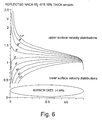
- the aerofoil 5 has been analysed using an Eppler program which calculates the velocity distribution and boundary layer development. At the Reynolds Number of interest, in the range 3 to 10 million, the program predicts no "bubble warnings" and no laminar or turbulent separation. The profile and its predicted velocity distributions at incidence angles from zero to 12 degrees are shown in Figure 6 .
- Figure 7 shows the results of the Eppler program.
- the drag coefficient lies below 0.010 at lift coefficients up to 0.5, which corresponds to about 4.5° incidence angle.
- the results for a 5 million Reynolds Number indicate a laminar flow "drag bucket" with the drag coefficient falling to 0.006 at zero incidence. This effect is stronger at even lower Reynolds Numbers.
- Model turbine tests have confirmed that a model ducted turbine using the aerofoil 5 achieved efficiencies of 80% to 85% in both directions, at Reynolds Numbers - based on blade chord - of round 300,000.
- the 15% thick aerofoil 5 described here provides a good compromise between structural and aerodynamic efficiency, but there are advantages to choosing other thicknesses in certain circumstances.
- the turbine blades will benefit from the increased rigidity of a 20% thickness-chord ratio at the root section and a thinner 12% thick form at the tip.
- the basic NACA 67 1 -015 thickness form can be scaled to any desired thickness before reflecting the profile about its mid-chord line.
- the performance of the resulting profile can then be checked using aerofoil and boundary layer analysis software or CFD.
- a more sophisticated approach is to use the Eppler program, for example, to design a novel but conventional symmetrical aerofoil having the desired thickness, with its maximum thickness at 50% chord, and then to reflect this profile about its mid-chord.
- the second method is more reliable because the original NACA profile was designed in a similar fashion and its aerodynamic properties are not necessarily retained when it is simply scaled.
- the design software ensures a favourable velocity distribution is achieved up to a certain prescribed value of incidence angle.
- the power generation apparatus 160 comprises a plurality of turbine units 130 and is similar to the power generation apparatus 60 of the first embodiment shown in Figure 5 , including blades (not shown) having the form of the aerofoil 5 of Figure 1 .
- the turbine units 130 of Figures 8 and 9 differ from the turbine units 30 of the power generation apparatus 60 of Figure 5 in that the turbine units 130 provide a part 165 releasably mountable in the turbine unit 130.
- the part 165 includes at least one of the turbine and the pump means (not shown).
- the part 165 includes at least part of the duct 135.
- the part 165 is releasable from the turbine unit 130 via an openably closeable part 170.
- the part 165 can be retrieved to surface by a vessel 175, or the like, for maintenance or replacement purposes and may thereafter be reinstalled or replaced in the turbine unit 130.
- the power generation apparatus 160 of Figures 8 and 9 therefore resembles the power generation apparatus disclosed in WO 03/029645 A1 (also by the present Applicant), but includes the novel and inventive aerofoil 5 of the present invention.
- the foregoing embodiments provide ducted turbines which do not need an underwater yawing mechanism but allow the tidal flow to power the turbine in either direction. This is achieved by the novel turbine blade design which provides a relatively high efficiency when operating with flow in either direction. As the turbine blade angle to the axial direction is relatively high, the direction of rotation of the turbine will be reversed when the tidal flow direction changes.
- turbine unit has one turbine
- a turbine unit may have more than one turbine, e.g. in series.
Landscapes
- Engineering & Computer Science (AREA)
- Mechanical Engineering (AREA)
- General Engineering & Computer Science (AREA)
- Chemical & Material Sciences (AREA)
- Combustion & Propulsion (AREA)
- Physics & Mathematics (AREA)
- Fluid Mechanics (AREA)
- General Life Sciences & Earth Sciences (AREA)
- Oceanography (AREA)
- Life Sciences & Earth Sciences (AREA)
- Power Engineering (AREA)
- Other Liquid Machine Or Engine Such As Wave Power Use (AREA)
- Hydraulic Turbines (AREA)
- Engine Equipment That Uses Special Cycles (AREA)
- Control Of Turbines (AREA)
Claims (44)
- Energieerzeugungsvorrichtung (60), die wenigstens eine Unterwasser-Turbineneinheit (30) umfasst, wobei die wenigstens eine Unterwasser-Turbineneinheit wenigstens eine Turbine (25) umfasst, wobei die wenigstens eine Turbine wenigstens eine Schaufel (20a-20e) umfasst, dadurch gekennzeichnet, dass die wenigstens eine Schaufel eine Vielzahl von Flügeln (5a-5e) umfasst, die mit Zwischenraum längs einer Länge der wenigstens einen Schaufel und zwischen einer Nabe und einer Spitze der wenigstens einen Schaufel angeordnet sind, wobei jeder Flügel eine Form hat, die symmetrisch um eine Sehnenmittellinie (A) desselben ist und die symmetrisch um eine Sehnenlinie (B) desselben ist, und wobei jeder Flügel eine erste und eine zweite Vorderkante (10, 15) umfasst und die erste und die zweite Vorderkante von benachbarten Flügeln so miteinander verbunden sind, dass sie jeweilige kontinuierliche erste und zweite Vorderkanten der wenigstens einen Schaufel bereitstellen, und wobei ferner ein Nabenanstellwinkel der wenigstens einen Schaufel in dem Bereich von 30° bis 60° von einer axialen Richtung liegt und ein Spitzenanstellwinkel der wenigstens einen Schaufel in dem Bereich von 70° bis 85° von einer axialen Richtung liegt.
- Energieerzeugungsvorrichtung nach Anspruch 1, wobei die wenigstens eine Turbineneinheit ein Gehäuse (35) einschließt, das einen Fluid-Durchflusskanal (40) durch dasselbe hat, wobei die wenigstens eine Turbine in dem Durchflusskanal angebracht ist, für eine Drehung als Reaktion auf einen Fluid-Durchfluss durch den Durchflusskanal.
- Energieerzeugungsvorrichtung nach einem der vorhergehenden Ansprüche, wobei jede Vorderkante von teilkreisförmiger Gestalt ist.
- Energieerzeugungsvorrichtung nach einem der vorhergehenden Ansprüche, wobei für jeden Flügel ein Verhältnis der Sehnenmittellinienhöhe oder -dicke zu der Sehnenlinienlänge 5% bis 25% beträgt.
- Energieerzeugungsvorrichtung nach einem der vorhergehenden Ansprüche, wobei für jeden Flügel ein Verhältnis der Sehnenmittellinienhöhe oder -dicke zu der Sehnenlinienlänge 12% bis 20% beträgt.
- Energieerzeugungsvorrichtung nach einem der vorhergehenden Ansprüche, wobei für jeden Flügel ein Verhältnis der Sehnenmittellinienhöhe oder -dicke zu der Sehnenlänge 15% beträgt.
- Energieerzeugungsvorrichtung nach einem der vorhergehenden Ansprüche, wobei jede Flügelform eine NACA-67-Vorderkantenform, die um die Sehnenmittellinie gespiegelt ist, umfasst.
- Energieerzeugungsvorrichtung nach einem der vorhergehenden Ansprüche, wobei jede Flügelform eine NACA-671-015-Vorderkantenform, die um die Sehnennittellinie gespiegelt ist, umfasst.
- Energieerzeugungsvorrichtung nach einem der vorhergehenden Ansprüche, wobei die wenigstens eine Schaufel 3 bis 9 Flügel umfasst.
- Energieerzeugungsvorrichtung nach einem der vorhergehenden Ansprüche, wobei die wenigstens eine Schaufel fünf Flügel umfasst.
- Energieerzeugungsvorrichtung nach einem der vorhergehenden Ansprüche, wobei ein Zuspitzungsverhältnis der wenigstens einen Schaufel in dem Bereich von 0,3 bis 0,8 liegt.
- Energieerzeugungsvorrichtung nach einem der vorhergehenden Ansprüche, wobei ein Zuspitzungsverhältnis 0,5 beträgt.
- Energieerzeugungsvorrichtung nach einem der vorhergehenden Ansprüche, wobei ein Zuschärfungsverhältnis der wenigstens einen Schaufel in dem Bereich von 3 bis 10 liegt.
- Energieerzeugungsvorrichtung nach einem der vorhergehenden Ansprüche, wobei ein Zuschärfungsverhältnis der wenigstens einen Schaufel rund 6 beträgt.
- Energieerzeugungsvorrichtung nach einem der vorhergehenden Ansprüche, wobei ein Nabenanstellwinkel der wenigstens einen Schaufel 45° oder 48° beträgt.
- Energieerzeugungsvorrichtung nach einem der vorhergehenden Ansprüche, wobei ein Spitzenanstellwinkel der wenigstens einen Schaufel 79° beträgt.
- Energieerzeugungsvorrichtung nach einem der vorhergehenden Ansprüche, wobei eine Sehnenlänge der wenigstens einen Schaufel bei der Mittelhöhe in dem Bereich von 0,3 m bis 3,0 m liegt.
- Energieerzeugungsvorrichtung nach einem der vorhergehenden Ansprüche, wobei eine Sehnenlänge der wenigstens einen Schaufel 1,0 m beträgt.
- Energieerzeugungsvorrichtung nach einem der vorhergehenden Ansprüche, wobei die wenigstens eine Schaufel eine Vielzahl von Schaufeln umfasst.
- Energieerzeugungsvorrichtung nach Anspruch 19, wobei die Vielzahl von Schaufeln 2 bis 9 Schaufeln umfasst.
- Energieerzeugungsvorrichtung nach einem der Ansprüche 19 oder 20, wobei die Vielzahl von Schaufeln 3 bis 7 Schaufeln umfasst.
- Energieerzeugungsvorrichtung nach einem der Ansprüche 19 bis 21, wobei die Vielzahl von Schaufeln 5 oder 7 Schaufeln umfasst.
- Energieerzeugungsvorrichtung nach einem der Ansprüche 19 bis 22, wobei ein Verhältnis des Nabendurchmessers zu dem Spitzendurchmesser der wenigstens einen Schaufel in dem Bereich von 0,1 bis 0,5 liegt.
- Energieerzeugungsvorrichtung nach einem der Ansprüche 19 bis 23, wobei ein Verhältnis des Nabendurchmessers zu dem Spitzendurchmesser der wenigstens einen Schaufel 0,2 beträgt.
- Energieerzeugungsvorrichtung nach einem der Ansprüche 19 bis 24, wobei ein Spitzendurchmesser in dem Bereich von 5 m bis 30 m liegt.
- Energieerzeugungsvorrichtung nach einem der Ansprüche 19 bis 25, wobei ein Spitzendurchmesser 15 m bis 20 m beträgt.
- Energieerzeugungsvorrichtung nach einem der Ansprüche 19 bis 26, wobei die Turbine dafür eingerichtet ist, sich bei Anwendung mit einer Geschwindigkeit von 10 bis 50 U/min zu drehen.
- Energieerzeugungsvorrichtung nach einem der Ansprüche 19 bis 27, wobei die Turbine dafür eingerichtet ist, sich bei Anwendung mit einer Geschwindigkeit von 25 U/min zu drehen.
- Energieerzeugungsvorrichtung nach Anspruch 2 oder einem der Ansprüche 3 bis 28, soweit abhängig von Anspruch 2, wobei der Durchflusskanal ein Venturi-Rohr umfasst, das ein konvergent-divergentes Venturi-Rohr umfasst, das sich von öffnungen an beiden Enden des Durchflusskanals zu einem inneren Teil des Durchflusskanals hin verjüngt.
- Energieerzeugungsvorrichtung nach Anspruch 2, wobei das Gehäuse im Wesentlichen symmetrisch um eine Mittelpunktsposition desselben ist und die/wenigstens eine der wenigsten einen Turbine(n) im Wesentlichen an derselben angeordnet ist.
- Energieerzeugungsvorrichtung nach einem der Ansprüche 29 bis 30, wobei das Turbinengehäuse eine äußere Gehäusehülse und eine innere Gehäusehülse umfasst, wobei die innere Hülse den Durchflusskanal definiert.
- Energieerzeugungsvorrichtung nach einem der Ansprüche 29 bis 31, wobei die Turbineneinheit einen Teil bereitstellt, der lösbar in der Turbineneinheit angebracht ist.
- Energieerzeugungsvorrichtung nach einem der Ansprüche 1 bis 32, wobei die Turbineneinheit bei Anwendung als Reaktion auf einen Fluid-durchfluss in beiden Richtungen durch den Durchflusskanal angetrieben wird.
- Energieerzeugungsvorrichtung nach Anspruch 2 oder einem der Ansprüche 3 bis 33, soweit abhängig von Anspruch 2, wobei ein Einlass- und/oder ein Auslassdurchmesser des Durchflusskanals oder der Durchführung ausgewählt ist von innerhalb des Bereichs von 7 m bis 40 m oder 20 m beträgt.
- Energieerzeugungsvorrichtung nach Anspruch 2 oder einem der Ansprüche 3 bis 34, soweit abhängig von Anspruch 2, wobei eine Länge des Durchflusskanals oder der Durchführung in dem Bereich von 7 m bis 50 m liegt.
- Energieerzeugungsvorrichtung nach einem der vorhergehenden Ansprüche, wobei die Energieerzeugungsvorrichtung einen Elektroenergie-Erzeuger umfasst.
- Energieerzeugungsvorrichtung nach Anspruch 36, wobei die Energieerzeugungsvorrichtung dafür eingerichtet ist, Elektroenergie als Wechselstrom/- spannung (WS) oder Gleichstrom/-spannung (GS) zu erzeugen.
- Verfahren zum Erzeugen von Energie, das die folgenden Schritte umfasst:das Bereitstellen einer Energieerzeugungsvorrichtung (60) nach einem der Ansprüche 1 bis 37,das Anordnen der wenigstens einen Turbineneinheit (30) der Energieerzeugungsvorrichtung unter Wasser,das Veranlassen, dass sich die wenigstens eine Turbine (25) der wenigstens einen Turbineneinheit als Reaktion auf einen Fluiddurchfluss in wenigstens einer Richtung dreht.
- Verfahren zum Erzeugen von Energie nach Anspruch 38, wobei die wenigstens eine Turbineneinheit auf, nahe oder über einem der folgenden angeordnet ist: einem Meeresgrund, einem Ozeanboden oder einer Fluss-Sohle.
- Verfahren zum Erzeugen von Energie nach Anspruch 38 oder 39, wobei der Fluiddurchfluss einen Gezeitendurchfluss oder einen Strömungsdurchfluss umfasst.
- Verfahren zum Erzeugen von Energie nach einem der Ansprüche 38 bis 40, wobei als Reaktion auf einen Fluiddurchfluss in einer Richtung sich die wenigstens eine Turbine in einer Richtung dreht und als Reaktion auf einen Fluiddurchfluss sich die wenigstens eine Turbine in einer anderen Richtung in einer anderen oder entgegengesetzten Richtung dreht.
- Verfahren zum Erzeugen von Energie nach Anspruch 38, wobei das Gehäuse durch eine Anbringungsstruktur an einer Unterwasserfläche befestigt ist und wahlweise im Wesentlichen mit einer Richtung eines Gezeiten- oder Strömungsdurchflusses ausgerichtet ist.
- Verfahren zum Erzeugen von Energie nach Anspruch 42, wobei ein Winkel zwischen einer axialen Richtung des Gehäuses und einer Richtung eines Gezeiten- oder Strömungsdurchflusses 0° bis 45° beträgt.
- Verfahren zum Erzeugen von Energie nach Anspruch 42, wobei ein Winkel zwischen einer axialen Richtung des Gehäuses und einer Richtung eines Gezeiten- oder Strömungsdurchflusses 0° beträgt.
Applications Claiming Priority (2)
| Application Number | Priority Date | Filing Date | Title |
|---|---|---|---|
| GBGB0510417.9A GB0510417D0 (en) | 2005-05-21 | 2005-05-21 | Improved turbine |
| PCT/GB2006/001843 WO2006125959A1 (en) | 2005-05-21 | 2006-05-18 | Water turbine with bi-symmetric airfoil |
Publications (2)
| Publication Number | Publication Date |
|---|---|
| EP1886015A1 EP1886015A1 (de) | 2008-02-13 |
| EP1886015B1 true EP1886015B1 (de) | 2011-12-21 |
Family
ID=34834443
Family Applications (1)
| Application Number | Title | Priority Date | Filing Date |
|---|---|---|---|
| EP06743936A Expired - Lifetime EP1886015B1 (de) | 2005-05-21 | 2006-05-18 | Vorrichtung zur energieerzeugung mit einer wasserturbine mit bisymmetrischer schaufel |
Country Status (13)
| Country | Link |
|---|---|
| US (1) | US8115329B2 (de) |
| EP (1) | EP1886015B1 (de) |
| JP (1) | JP2008540928A (de) |
| KR (1) | KR101333762B1 (de) |
| CN (1) | CN101223355A (de) |
| AT (1) | ATE538306T1 (de) |
| AU (1) | AU2006250972B2 (de) |
| CA (1) | CA2609014C (de) |
| GB (3) | GB0510417D0 (de) |
| NO (1) | NO20075941L (de) |
| NZ (1) | NZ564539A (de) |
| WO (1) | WO2006125959A1 (de) |
| ZA (1) | ZA200710394B (de) |
Families Citing this family (65)
| Publication number | Priority date | Publication date | Assignee | Title |
|---|---|---|---|---|
| GB0123802D0 (en) * | 2001-10-04 | 2001-11-21 | Rotech Holdings Ltd | Power generator and turbine unit |
| CN101248268B (zh) * | 2005-08-25 | 2011-05-25 | 株式会社能量应用技术研究所 | 发电装置及发电方法 |
| US20110049894A1 (en) * | 2006-10-06 | 2011-03-03 | Green William M | Electricity Generating Assembly |
| GB0704897D0 (en) * | 2007-03-14 | 2007-04-18 | Rotech Holdings Ltd | Power generator and turbine unit |
| US8026625B2 (en) * | 2007-06-20 | 2011-09-27 | California Institute Of Technology | Power generation systems and methods |
| US7605490B2 (en) * | 2007-12-10 | 2009-10-20 | Simon Srybnik | Transportable hydro-electric system |
| US7564144B1 (en) * | 2008-11-20 | 2009-07-21 | Simon Srybnik | Transportable hydro-electric generating system with improved water pressure enhancement feature activation systems |
| US7928594B2 (en) * | 2007-12-14 | 2011-04-19 | Vladimir Anatol Shreider | Apparatus for receiving and transferring kinetic energy from a flow and wave |
| DE102008007043A1 (de) * | 2008-01-31 | 2009-08-06 | Voith Patent Gmbh | Freistehende, tauchende Energieerzeugungsanlage mit einer Axialturbine |
| GB0806666D0 (en) * | 2008-04-11 | 2008-05-14 | Bond Philip C | Windfarm radar clutter mitigation |
| CN102066667B (zh) | 2008-04-14 | 2014-09-17 | 亚特兰蒂斯能源有限公司 | 中心轴线式水力涡轮机 |
| AU2009238206B2 (en) | 2008-04-14 | 2013-03-14 | Atlantis Resources Corporation Pte Limited | Blade for a water turbine |
| DE102008020965A1 (de) * | 2008-04-25 | 2009-10-29 | Voith Patent Gmbh | Vorrichtung und Verfahren für die Montage und den Service von Unterwasserkraftwerken |
| DE102008037896A1 (de) * | 2008-08-15 | 2010-02-18 | Ksb Aktiengesellschaft | Energierückgewinnungseinrichtung und Verfahren zur Auslegung |
| US8193653B2 (en) * | 2010-05-07 | 2012-06-05 | Israel Ortiz | Automatic pitch turbine |
| ITVE20090004A1 (it) * | 2009-01-22 | 2009-04-23 | Claudio Berti | Trasformatore di moto ondoso e/o flussi in modo rotativo:condotto saturatore con elica a flusso assiale a pale indipendenti auto orientabili |
| JP5290031B2 (ja) * | 2009-04-09 | 2013-09-18 | 株式会社クボタ | 攪拌機用羽根 |
| KR20120042746A (ko) | 2009-04-28 | 2012-05-03 | 아틀란티스 리소시스 코포레이션 피티이 리미티드 | 수중 동력 발생기 |
| KR20120024659A (ko) * | 2009-04-28 | 2012-03-14 | 아틀란티스 리소시스 코포레이션 피티이 리미티드 | 양방향 터빈 블레이드 |
| EP2494186A4 (de) | 2009-10-27 | 2013-05-15 | Atlantis Resources Corp Pte | Untersee-stromgenerator |
| DE102009051117B4 (de) | 2009-10-28 | 2014-12-11 | Voith Patent Gmbh | Horizontalläufer-Turbine mit passiver Gierwinkel-Einstellvorrichtung |
| DE102009057449B3 (de) | 2009-12-09 | 2011-04-21 | Voith Patent Gmbh | Turbinenblatt für eine bidirektional anströmbare Wasserturbine |
| ITMI20100160A1 (it) * | 2010-02-03 | 2011-08-04 | Tecnedil Srl | Apparecchiatura per la generazione di energia elettrica attraverso lo sfruttamento delle correnti marine e dei corsi d'acqua in generale. |
| US8573890B2 (en) * | 2010-07-27 | 2013-11-05 | Donald H Gehring | Marine power generator deployment and retrieval system |
| US20120027526A1 (en) * | 2010-07-29 | 2012-02-02 | Saint Louis University | Method and structure for reducing turbulence around and erosion of underwater structures |
| FR2965591B1 (fr) | 2010-09-30 | 2012-08-31 | Alstom Hydro France | Poutre de supportage d'un carenage d'hydrolienne et hydrolienne comportant une telle poutre |
| KR101127565B1 (ko) * | 2011-01-28 | 2012-03-23 | (주)레네테크 | 조류 발전 장치 |
| US20140037449A1 (en) * | 2011-03-28 | 2014-02-06 | Norman Perner | Power Plant for Obtaining Energy from a Flow of a Body of Water, and Method for the Operation Thereof |
| GB201105620D0 (en) * | 2011-04-04 | 2011-05-18 | Qed Naval Ltd | Submersible apparatus and methods of installing anchoring equipment |
| JP5629035B2 (ja) | 2011-05-10 | 2014-11-19 | アトランティス リソーセズ コーポレーション ピーティーイー リミテッド | 水中発電装置を配備する配備装置および方法 |
| US20130028729A1 (en) * | 2011-07-28 | 2013-01-31 | Jones Jack A | Power generation systems and methods |
| GB201113694D0 (en) * | 2011-08-09 | 2011-09-21 | Univ Southampton | Turbine generator |
| FR2980244B1 (fr) | 2011-09-19 | 2014-07-04 | Sabella | Pale d'hydrolienne |
| US20130221673A1 (en) * | 2012-02-23 | 2013-08-29 | Ping-Chih Liu | Power generating unit |
| NL2008948C2 (nl) * | 2012-06-06 | 2013-12-09 | G A M Manshanden Man B V | Scheepsschroef. |
| KR101331961B1 (ko) * | 2012-10-23 | 2013-11-22 | 한국에너지기술연구원 | 공력제어장치 삽입이 가능한 뒷전 형상을 갖는 풍력발전기의 블레이드 에어포일 |
| US20150204301A1 (en) * | 2014-01-22 | 2015-07-23 | Dayton Hydro Electric Ltd. | Systems and methods for hydroelectric systems |
| US20160003212A1 (en) * | 2014-07-07 | 2016-01-07 | Stephanie M. Holt | Underwater Multi-Turbine Generator |
| JP5995222B2 (ja) * | 2014-09-09 | 2016-09-21 | 悠一 桐生 | 潮流発電に用いる水力発電ユニット |
| JP6282203B2 (ja) * | 2014-09-12 | 2018-02-21 | 株式会社日立製作所 | 風力発電装置及び軸流タイプブレード |
| KR101711630B1 (ko) * | 2014-09-23 | 2017-03-03 | 한국생산기술연구원 | 역회전형 펌프 터빈의 최적화 설계 방법, 이에 의하여 설계된 역회전형 펌프 터빈 및 자가 발전 시스템 |
| US9845684B2 (en) * | 2014-11-25 | 2017-12-19 | Pratt & Whitney Canada Corp. | Airfoil with stepped spanwise thickness distribution |
| AU2016232976B2 (en) * | 2015-03-17 | 2017-12-07 | Altum Green Energy Limited | A rotor for an electricity generator |
| US10814948B2 (en) * | 2015-08-25 | 2020-10-27 | Fmc Technologies Do Brasil Ltda | Electric power generating submarine tool |
| US9759179B2 (en) * | 2015-09-18 | 2017-09-12 | Charles B. Culpepper | Hydroelectric generator system including helical longitudinal blades forming an open bore and aligned with a current direction |
| US10197038B2 (en) * | 2015-09-18 | 2019-02-05 | Charles B. Culpepper | Helical longitudinal blade turbine system including a funnel throat valve comprising a plurality of semi-circular valve plates |
| CN105484927B (zh) * | 2016-01-14 | 2018-10-02 | 杭州江河水电科技有限公司 | 海洋直流电源装置 |
| NO20160787A1 (en) * | 2016-05-10 | 2017-06-19 | Norwegian Tidal Solutions | Underwater electrical power plant |
| CN108361140A (zh) * | 2017-01-27 | 2018-08-03 | 巩志科 | 悬浮型立体过流水力发电系统 |
| US9784244B1 (en) * | 2017-03-29 | 2017-10-10 | Tarek O. Souryal | Energy collection pod |
| US20200049124A1 (en) * | 2018-08-09 | 2020-02-13 | Matthew Wayne Harker | Harker oceanic power station |
| US10947953B2 (en) * | 2018-08-20 | 2021-03-16 | Hydrospark, Inc. | Secondary electric power system and method |
| GB201818684D0 (en) | 2018-11-16 | 2019-01-02 | Rolls Royce Plc | Boundary layer ingestion fan system |
| GB201818686D0 (en) | 2018-11-16 | 2019-01-02 | Rolls Royce Plc | Boundary layer ingestion fan system |
| GB201818681D0 (en) | 2018-11-16 | 2019-01-02 | Rolls Royce Plc | Boundary layer ingestion fan system |
| GB201818683D0 (en) | 2018-11-16 | 2019-01-02 | Rolls Royce Plc | Boundary layer ingestion fan system |
| GB201818680D0 (en) | 2018-11-16 | 2019-01-02 | Rolls Royce Plc | Boundary layer ingestion fan system |
| GB201818682D0 (en) | 2018-11-16 | 2019-01-02 | Rolls Royce Plc | Boundary layer ingestion fan system |
| GB201818687D0 (en) | 2018-11-16 | 2019-01-02 | Rolls Royce Plc | Boundary layer ingestion fan system |
| CN109681462B (zh) * | 2019-01-08 | 2020-09-15 | 扬州大学 | 采用椭尖形组合翼型的可逆式轴流泵叶轮 |
| AU2020236379B2 (en) | 2019-03-08 | 2023-08-17 | Big Moon Power, Inc. | Systems and methods for hydro-based electric power generation |
| AU2020429933A1 (en) * | 2019-11-22 | 2022-05-12 | Gradiant Corporation | Turbines and associated components, systems and methods |
| BR102020007224B1 (pt) * | 2020-04-10 | 2021-10-26 | Mauricio Otaviano De Queiroz | Unidade coletora de energia de corrente |
| US11353001B1 (en) | 2021-04-30 | 2022-06-07 | Sitkana Inc. | Hydrokinetic generator |
| CN115081138B (zh) * | 2022-06-22 | 2024-05-31 | 武汉大学 | 改善水泵水轮机运行稳定性的导叶设计方法和水泵水轮机 |
Family Cites Families (29)
| Publication number | Priority date | Publication date | Assignee | Title |
|---|---|---|---|---|
| CH104164A (de) | 1923-05-17 | 1924-06-16 | Escher Wyss Maschf Ag | Leit- oder Laufschaufeln für Kreiselmaschinen, insbesondere Wasser-, Dampf- und Gasturbinen. |
| US1769767A (en) * | 1924-09-20 | 1930-07-01 | Hamilton Standard Propeller Co | Propeller |
| GB296717A (en) * | 1927-06-02 | 1928-09-03 | Stone J & Co Ltd | Improvements in screw propellers |
| GB375327A (en) * | 1930-01-23 | 1932-06-14 | Gerard Post Herrick | Improvements in or relating to aerofoils |
| GB379647A (en) * | 1932-04-05 | 1932-09-01 | Wilhelm Muhs | Improvements in and relating to propelling screws |
| GB435993A (en) * | 1934-01-06 | 1935-10-07 | Alexander Frederick Ainslie | Improvements in and relating to screw propellers |
| US2043736A (en) * | 1935-02-07 | 1936-06-09 | Hartzell Industries | Ventilating fan |
| US2160467A (en) * | 1937-09-22 | 1939-05-30 | Edgar T Ward | Propeller |
| GB626780A (en) * | 1947-04-25 | 1949-07-21 | Alan Arnold Griffith | Improvements relating to aerofoils and aerofoil blading |
| US2709052A (en) * | 1952-04-15 | 1955-05-24 | Charles J Fletcher | Spanwise flow control of fluid swept lifting surfaces |
| CH316900A (de) | 1953-04-15 | 1956-10-31 | Escher Wyss Ag | Hydroelektrische Maschinenanlage mit gegenläufigen Laufrädern |
| FR1353655A (fr) | 1963-01-19 | 1964-02-28 | Grenobloise Etude Appl | Hydroréacteur |
| JPS528244A (en) * | 1975-07-09 | 1977-01-21 | Mitsui Eng & Shipbuild Co Ltd | Floating wave power plant with propeller turbine |
| JPS5282244A (en) | 1975-12-27 | 1977-07-09 | Toyo Dengu Seisakushiyo Kk | Thermal print head |
| GB1574379A (en) | 1977-08-24 | 1980-09-03 | English Electric Co Ltd | Turbines and like rotary machines |
| GB2028929B (en) | 1978-08-29 | 1982-07-07 | English Electric Co Ltd | Turbines |
| GB2036870A (en) * | 1978-12-15 | 1980-07-02 | Utile Eng Co Ltd | Regenerative Turbo Machine |
| US4830574A (en) * | 1988-02-29 | 1989-05-16 | United Technologies Corporation | Airfoiled blade |
| US5088894A (en) * | 1990-05-02 | 1992-02-18 | Westinghouse Electric Corp. | Turbomachine blade fastening |
| US5112192A (en) * | 1990-07-26 | 1992-05-12 | General Signal Corporation | Mixing impellers and impeller systems for mixing and blending liquids and liquid suspensions having a wide range of viscosities |
| GB9022713D0 (en) | 1990-10-18 | 1990-11-28 | Wells Alan A | Wave power apparatus |
| IL105107A (en) * | 1992-03-18 | 1996-06-18 | Advanced Wind Turbines Inc | Wind turbines |
| AUPO361396A0 (en) | 1996-11-14 | 1996-12-12 | Energetech Australia Pty Limited | Parabolic wave focuser & double ended aerofoil turbine |
| US5791878A (en) * | 1997-03-10 | 1998-08-11 | United Technologies Corporation | Airfoiled blade for cargo transport aircraft |
| US6068446A (en) * | 1997-11-20 | 2000-05-30 | Midwest Research Institute | Airfoils for wind turbine |
| US6104097A (en) | 1999-03-04 | 2000-08-15 | Lehoczky; Kalman N. | Underwater hydro-turbine for hydrogen production |
| RU2301911C2 (ru) * | 2001-07-11 | 2007-06-27 | Хюдра Тидаль Энерджи Текнолоджи Ас | Электростанция, генератор и элемент пропеллера для получения энергии с использованием потока воды |
| GB0123802D0 (en) * | 2001-10-04 | 2001-11-21 | Rotech Holdings Ltd | Power generator and turbine unit |
| DK200300670A (da) * | 2003-05-05 | 2004-11-06 | Lm Glasfiber As | Vindmölleving med opdriftsregulerende organer |
-
2005
- 2005-05-21 GB GBGB0510417.9A patent/GB0510417D0/en not_active Ceased
-
2006
- 2006-05-18 KR KR1020077028627A patent/KR101333762B1/ko not_active Expired - Fee Related
- 2006-05-18 CA CA2609014A patent/CA2609014C/en not_active Expired - Fee Related
- 2006-05-18 NZ NZ564539A patent/NZ564539A/en not_active IP Right Cessation
- 2006-05-18 CN CNA2006800249268A patent/CN101223355A/zh active Pending
- 2006-05-18 AU AU2006250972A patent/AU2006250972B2/en not_active Ceased
- 2006-05-18 EP EP06743936A patent/EP1886015B1/de not_active Expired - Lifetime
- 2006-05-18 WO PCT/GB2006/001843 patent/WO2006125959A1/en not_active Ceased
- 2006-05-18 GB GB0609832A patent/GB2426295B/en not_active Expired - Fee Related
- 2006-05-18 AT AT06743936T patent/ATE538306T1/de active
- 2006-05-18 US US11/914,757 patent/US8115329B2/en not_active Expired - Fee Related
- 2006-05-18 GB GB1102602A patent/GB2475196B/en not_active Expired - Fee Related
- 2006-05-18 JP JP2008511792A patent/JP2008540928A/ja active Pending
-
2007
- 2007-11-20 NO NO20075941A patent/NO20075941L/no unknown
- 2007-11-29 ZA ZA200710394A patent/ZA200710394B/xx unknown
Also Published As
| Publication number | Publication date |
|---|---|
| CA2609014A1 (en) | 2006-11-30 |
| GB2426295B (en) | 2011-05-18 |
| GB0510417D0 (en) | 2005-06-29 |
| GB0609832D0 (en) | 2006-06-28 |
| NZ564539A (en) | 2011-04-29 |
| WO2006125959A1 (en) | 2006-11-30 |
| GB2475196A (en) | 2011-05-11 |
| GB2426295A (en) | 2006-11-22 |
| EP1886015A1 (de) | 2008-02-13 |
| GB2475196B (en) | 2011-07-13 |
| ZA200710394B (en) | 2008-10-29 |
| KR101333762B1 (ko) | 2013-11-28 |
| CA2609014C (en) | 2015-07-14 |
| CN101223355A (zh) | 2008-07-16 |
| ATE538306T1 (de) | 2012-01-15 |
| US20080265583A1 (en) | 2008-10-30 |
| GB201102602D0 (en) | 2011-03-30 |
| AU2006250972B2 (en) | 2012-03-29 |
| AU2006250972A1 (en) | 2006-11-30 |
| JP2008540928A (ja) | 2008-11-20 |
| KR20080018184A (ko) | 2008-02-27 |
| NO20075941L (no) | 2008-02-19 |
| US8115329B2 (en) | 2012-02-14 |
Similar Documents
| Publication | Publication Date | Title |
|---|---|---|
| US8115329B2 (en) | Water turbine with bi-symmetric airfoil | |
| US8376686B2 (en) | Water turbines with mixers and ejectors | |
| CA2725231C (en) | Water turbines with mixers and ejectors | |
| US20110148117A1 (en) | Underwater turbine with finned diffuser for flow enhancement | |
| US20140265335A1 (en) | Ultra high efficiency power generation system and water turbine | |
| CN107429656A (zh) | 水电/水力涡轮机及其制造和使用方法 | |
| CN107662693A (zh) | 一种带有导管的吊舱推进器 | |
| WO2020210166A1 (en) | Retractable hydrofoil on vessel | |
| JP5064853B2 (ja) | 螺旋翼推進、没水浮き双胴船 | |
| KR101292911B1 (ko) | 선속 향상 및 선미부의 유동 개선을 위한 선미 부가물 | |
| CN113464344B (zh) | 一种水平轴潮流能水轮机及使用方法 | |
| US20250341197A1 (en) | Horizontally-oriented conical-helical hydrokinetic turbine | |
| JP6158019B2 (ja) | 軸流水車発電装置 | |
| JP2009051283A (ja) | ダクト付きタービンフィン | |
| KR20130002144U (ko) | 선박용 프로펠러 | |
| KR100433598B1 (ko) | 저속 비대선용 연직형 전류고정날개 | |
| Pashias et al. | Design optimization of a bi-directional integrated thruster | |
| KR101292954B1 (ko) | 선속 및 프로펠러 효율 향상을 위한 선미 부가물 | |
| GB2532989A (en) | A tidal turbine blade | |
| WO2025235332A1 (en) | Horizontally-oriented conical-helical hydrokinetic turbine | |
| WO2023017470A1 (en) | Helical turbine | |
| CN119370303A (zh) | 一种轴流式喷水推进泵 | |
| CN120716907A (zh) | 一种基于海豚背鳍外形叶切面的仿生螺旋桨及桨叶 | |
| NZ734223B2 (en) | Hydroelectric/hydrokinetic turbine and methods for making and using same |
Legal Events
| Date | Code | Title | Description |
|---|---|---|---|
| PUAI | Public reference made under article 153(3) epc to a published international application that has entered the european phase |
Free format text: ORIGINAL CODE: 0009012 |
|
| 17P | Request for examination filed |
Effective date: 20071203 |
|
| AK | Designated contracting states |
Kind code of ref document: A1 Designated state(s): AT BE BG CH CY CZ DE DK EE ES FI FR GB GR HU IE IS IT LI LT LU LV MC NL PL PT RO SE SI SK TR |
|
| DAX | Request for extension of the european patent (deleted) | ||
| GRAP | Despatch of communication of intention to grant a patent |
Free format text: ORIGINAL CODE: EPIDOSNIGR1 |
|
| RTI1 | Title (correction) |
Free format text: POWER GENERATING APPARATUS WITH WATER TURBINE WITH BI-SYMMETRIC AIRFOIL |
|
| GRAS | Grant fee paid |
Free format text: ORIGINAL CODE: EPIDOSNIGR3 |
|
| GRAA | (expected) grant |
Free format text: ORIGINAL CODE: 0009210 |
|
| AK | Designated contracting states |
Kind code of ref document: B1 Designated state(s): AT BE BG CH CY CZ DE DK EE ES FI FR GB GR HU IE IS IT LI LT LU LV MC NL PL PT RO SE SI SK TR |
|
| REG | Reference to a national code |
Ref country code: GB Ref legal event code: FG4D |
|
| REG | Reference to a national code |
Ref country code: CH Ref legal event code: EP |
|
| REG | Reference to a national code |
Ref country code: AT Ref legal event code: REF Ref document number: 538306 Country of ref document: AT Kind code of ref document: T Effective date: 20120115 |
|
| REG | Reference to a national code |
Ref country code: IE Ref legal event code: FG4D |
|
| REG | Reference to a national code |
Ref country code: DE Ref legal event code: R096 Ref document number: 602006026537 Country of ref document: DE Effective date: 20120216 |
|
| REG | Reference to a national code |
Ref country code: NL Ref legal event code: VDEP Effective date: 20111221 |
|
| PG25 | Lapsed in a contracting state [announced via postgrant information from national office to epo] |
Ref country code: LT Free format text: LAPSE BECAUSE OF FAILURE TO SUBMIT A TRANSLATION OF THE DESCRIPTION OR TO PAY THE FEE WITHIN THE PRESCRIBED TIME-LIMIT Effective date: 20111221 |
|
| LTIE | Lt: invalidation of european patent or patent extension |
Effective date: 20111221 |
|
| PG25 | Lapsed in a contracting state [announced via postgrant information from national office to epo] |
Ref country code: SI Free format text: LAPSE BECAUSE OF FAILURE TO SUBMIT A TRANSLATION OF THE DESCRIPTION OR TO PAY THE FEE WITHIN THE PRESCRIBED TIME-LIMIT Effective date: 20111221 Ref country code: SE Free format text: LAPSE BECAUSE OF FAILURE TO SUBMIT A TRANSLATION OF THE DESCRIPTION OR TO PAY THE FEE WITHIN THE PRESCRIBED TIME-LIMIT Effective date: 20111221 Ref country code: GR Free format text: LAPSE BECAUSE OF FAILURE TO SUBMIT A TRANSLATION OF THE DESCRIPTION OR TO PAY THE FEE WITHIN THE PRESCRIBED TIME-LIMIT Effective date: 20120322 Ref country code: NL Free format text: LAPSE BECAUSE OF FAILURE TO SUBMIT A TRANSLATION OF THE DESCRIPTION OR TO PAY THE FEE WITHIN THE PRESCRIBED TIME-LIMIT Effective date: 20111221 Ref country code: LV Free format text: LAPSE BECAUSE OF FAILURE TO SUBMIT A TRANSLATION OF THE DESCRIPTION OR TO PAY THE FEE WITHIN THE PRESCRIBED TIME-LIMIT Effective date: 20111221 |
|
| PG25 | Lapsed in a contracting state [announced via postgrant information from national office to epo] |
Ref country code: BE Free format text: LAPSE BECAUSE OF FAILURE TO SUBMIT A TRANSLATION OF THE DESCRIPTION OR TO PAY THE FEE WITHIN THE PRESCRIBED TIME-LIMIT Effective date: 20111221 Ref country code: CY Free format text: LAPSE BECAUSE OF FAILURE TO SUBMIT A TRANSLATION OF THE DESCRIPTION OR TO PAY THE FEE WITHIN THE PRESCRIBED TIME-LIMIT Effective date: 20111221 |
|
| PG25 | Lapsed in a contracting state [announced via postgrant information from national office to epo] |
Ref country code: SK Free format text: LAPSE BECAUSE OF FAILURE TO SUBMIT A TRANSLATION OF THE DESCRIPTION OR TO PAY THE FEE WITHIN THE PRESCRIBED TIME-LIMIT Effective date: 20111221 Ref country code: EE Free format text: LAPSE BECAUSE OF FAILURE TO SUBMIT A TRANSLATION OF THE DESCRIPTION OR TO PAY THE FEE WITHIN THE PRESCRIBED TIME-LIMIT Effective date: 20111221 Ref country code: BG Free format text: LAPSE BECAUSE OF FAILURE TO SUBMIT A TRANSLATION OF THE DESCRIPTION OR TO PAY THE FEE WITHIN THE PRESCRIBED TIME-LIMIT Effective date: 20120321 Ref country code: IS Free format text: LAPSE BECAUSE OF FAILURE TO SUBMIT A TRANSLATION OF THE DESCRIPTION OR TO PAY THE FEE WITHIN THE PRESCRIBED TIME-LIMIT Effective date: 20120421 Ref country code: CZ Free format text: LAPSE BECAUSE OF FAILURE TO SUBMIT A TRANSLATION OF THE DESCRIPTION OR TO PAY THE FEE WITHIN THE PRESCRIBED TIME-LIMIT Effective date: 20111221 |
|
| PG25 | Lapsed in a contracting state [announced via postgrant information from national office to epo] |
Ref country code: PT Free format text: LAPSE BECAUSE OF FAILURE TO SUBMIT A TRANSLATION OF THE DESCRIPTION OR TO PAY THE FEE WITHIN THE PRESCRIBED TIME-LIMIT Effective date: 20120423 Ref country code: RO Free format text: LAPSE BECAUSE OF FAILURE TO SUBMIT A TRANSLATION OF THE DESCRIPTION OR TO PAY THE FEE WITHIN THE PRESCRIBED TIME-LIMIT Effective date: 20111221 Ref country code: PL Free format text: LAPSE BECAUSE OF FAILURE TO SUBMIT A TRANSLATION OF THE DESCRIPTION OR TO PAY THE FEE WITHIN THE PRESCRIBED TIME-LIMIT Effective date: 20111221 |
|
| REG | Reference to a national code |
Ref country code: AT Ref legal event code: MK05 Ref document number: 538306 Country of ref document: AT Kind code of ref document: T Effective date: 20111221 |
|
| PLBI | Opposition filed |
Free format text: ORIGINAL CODE: 0009260 |
|
| PLAX | Notice of opposition and request to file observation + time limit sent |
Free format text: ORIGINAL CODE: EPIDOSNOBS2 |
|
| 26 | Opposition filed |
Opponent name: VOITH HYDRO OCEAN CURRENT TECHNOLOGIES GMBH & CO. Effective date: 20120920 |
|
| PG25 | Lapsed in a contracting state [announced via postgrant information from national office to epo] |
Ref country code: DK Free format text: LAPSE BECAUSE OF FAILURE TO SUBMIT A TRANSLATION OF THE DESCRIPTION OR TO PAY THE FEE WITHIN THE PRESCRIBED TIME-LIMIT Effective date: 20111221 |
|
| PG25 | Lapsed in a contracting state [announced via postgrant information from national office to epo] |
Ref country code: IT Free format text: LAPSE BECAUSE OF FAILURE TO SUBMIT A TRANSLATION OF THE DESCRIPTION OR TO PAY THE FEE WITHIN THE PRESCRIBED TIME-LIMIT Effective date: 20111221 |
|
| REG | Reference to a national code |
Ref country code: DE Ref legal event code: R026 Ref document number: 602006026537 Country of ref document: DE Effective date: 20120920 |
|
| PG25 | Lapsed in a contracting state [announced via postgrant information from national office to epo] |
Ref country code: MC Free format text: LAPSE BECAUSE OF NON-PAYMENT OF DUE FEES Effective date: 20120531 |
|
| REG | Reference to a national code |
Ref country code: CH Ref legal event code: PL |
|
| PG25 | Lapsed in a contracting state [announced via postgrant information from national office to epo] |
Ref country code: CH Free format text: LAPSE BECAUSE OF NON-PAYMENT OF DUE FEES Effective date: 20120531 Ref country code: LI Free format text: LAPSE BECAUSE OF NON-PAYMENT OF DUE FEES Effective date: 20120531 Ref country code: AT Free format text: LAPSE BECAUSE OF FAILURE TO SUBMIT A TRANSLATION OF THE DESCRIPTION OR TO PAY THE FEE WITHIN THE PRESCRIBED TIME-LIMIT Effective date: 20111221 |
|
| PLBB | Reply of patent proprietor to notice(s) of opposition received |
Free format text: ORIGINAL CODE: EPIDOSNOBS3 |
|
| REG | Reference to a national code |
Ref country code: DE Ref legal event code: R119 Ref document number: 602006026537 Country of ref document: DE Effective date: 20121201 |
|
| PG25 | Lapsed in a contracting state [announced via postgrant information from national office to epo] |
Ref country code: ES Free format text: LAPSE BECAUSE OF FAILURE TO SUBMIT A TRANSLATION OF THE DESCRIPTION OR TO PAY THE FEE WITHIN THE PRESCRIBED TIME-LIMIT Effective date: 20120401 |
|
| PG25 | Lapsed in a contracting state [announced via postgrant information from national office to epo] |
Ref country code: DE Free format text: LAPSE BECAUSE OF NON-PAYMENT OF DUE FEES Effective date: 20121201 Ref country code: FI Free format text: LAPSE BECAUSE OF FAILURE TO SUBMIT A TRANSLATION OF THE DESCRIPTION OR TO PAY THE FEE WITHIN THE PRESCRIBED TIME-LIMIT Effective date: 20111221 |
|
| PG25 | Lapsed in a contracting state [announced via postgrant information from national office to epo] |
Ref country code: TR Free format text: LAPSE BECAUSE OF FAILURE TO SUBMIT A TRANSLATION OF THE DESCRIPTION OR TO PAY THE FEE WITHIN THE PRESCRIBED TIME-LIMIT Effective date: 20111221 |
|
| PG25 | Lapsed in a contracting state [announced via postgrant information from national office to epo] |
Ref country code: LU Free format text: LAPSE BECAUSE OF NON-PAYMENT OF DUE FEES Effective date: 20120518 |
|
| PG25 | Lapsed in a contracting state [announced via postgrant information from national office to epo] |
Ref country code: HU Free format text: LAPSE BECAUSE OF FAILURE TO SUBMIT A TRANSLATION OF THE DESCRIPTION OR TO PAY THE FEE WITHIN THE PRESCRIBED TIME-LIMIT Effective date: 20060518 |
|
| PLCK | Communication despatched that opposition was rejected |
Free format text: ORIGINAL CODE: EPIDOSNREJ1 |
|
| REG | Reference to a national code |
Ref country code: FR Ref legal event code: PLFP Year of fee payment: 10 |
|
| PGFP | Annual fee paid to national office [announced via postgrant information from national office to epo] |
Ref country code: GB Payment date: 20150513 Year of fee payment: 10 |
|
| PLBN | Opposition rejected |
Free format text: ORIGINAL CODE: 0009273 |
|
| STAA | Information on the status of an ep patent application or granted ep patent |
Free format text: STATUS: OPPOSITION REJECTED |
|
| PGFP | Annual fee paid to national office [announced via postgrant information from national office to epo] |
Ref country code: FR Payment date: 20150508 Year of fee payment: 10 Ref country code: IE Payment date: 20150512 Year of fee payment: 10 |
|
| 27O | Opposition rejected |
Effective date: 20150510 |
|
| GBPC | Gb: european patent ceased through non-payment of renewal fee |
Effective date: 20160518 |
|
| REG | Reference to a national code |
Ref country code: IE Ref legal event code: MM4A |
|
| REG | Reference to a national code |
Ref country code: FR Ref legal event code: ST Effective date: 20170131 |
|
| PG25 | Lapsed in a contracting state [announced via postgrant information from national office to epo] |
Ref country code: FR Free format text: LAPSE BECAUSE OF NON-PAYMENT OF DUE FEES Effective date: 20160531 |
|
| PG25 | Lapsed in a contracting state [announced via postgrant information from national office to epo] |
Ref country code: IE Free format text: LAPSE BECAUSE OF NON-PAYMENT OF DUE FEES Effective date: 20160518 Ref country code: GB Free format text: LAPSE BECAUSE OF NON-PAYMENT OF DUE FEES Effective date: 20160518 |