EP1886146B1 - Microdistributeur et procede correspondant pour l'utiliser - Google Patents
Microdistributeur et procede correspondant pour l'utiliser Download PDFInfo
- Publication number
- EP1886146B1 EP1886146B1 EP06753953A EP06753953A EP1886146B1 EP 1886146 B1 EP1886146 B1 EP 1886146B1 EP 06753953 A EP06753953 A EP 06753953A EP 06753953 A EP06753953 A EP 06753953A EP 1886146 B1 EP1886146 B1 EP 1886146B1
- Authority
- EP
- European Patent Office
- Prior art keywords
- microdispenser
- sample
- sample container
- nozzle
- dispensing
- Prior art date
- Legal status (The legal status is an assumption and is not a legal conclusion. Google has not performed a legal analysis and makes no representation as to the accuracy of the status listed.)
- Not-in-force
Links
- 238000011017 operating method Methods 0.000 title claims description 13
- 239000007788 liquid Substances 0.000 claims abstract description 40
- 238000003860 storage Methods 0.000 claims abstract description 29
- 239000011521 glass Substances 0.000 claims description 17
- 238000011049 filling Methods 0.000 claims description 16
- 238000000576 coating method Methods 0.000 claims description 8
- 239000011248 coating agent Substances 0.000 claims description 6
- 239000000463 material Substances 0.000 claims description 6
- 239000004033 plastic Substances 0.000 claims description 6
- 239000012530 fluid Substances 0.000 claims description 5
- 239000000853 adhesive Substances 0.000 claims description 2
- 230000001070 adhesive effect Effects 0.000 claims description 2
- 239000000919 ceramic Substances 0.000 claims description 2
- 230000015271 coagulation Effects 0.000 claims description 2
- 238000005345 coagulation Methods 0.000 claims description 2
- 230000003287 optical effect Effects 0.000 claims description 2
- 238000000746 purification Methods 0.000 claims description 2
- 238000001179 sorption measurement Methods 0.000 claims description 2
- 238000013022 venting Methods 0.000 claims description 2
- 238000007599 discharging Methods 0.000 claims 1
- 239000000523 sample Substances 0.000 description 144
- 230000032258 transport Effects 0.000 description 16
- 239000000126 substance Substances 0.000 description 12
- 238000011109 contamination Methods 0.000 description 10
- 238000013461 design Methods 0.000 description 10
- 238000000034 method Methods 0.000 description 10
- 238000004519 manufacturing process Methods 0.000 description 8
- 230000035939 shock Effects 0.000 description 6
- 239000011888 foil Substances 0.000 description 5
- 238000004458 analytical method Methods 0.000 description 4
- 239000012528 membrane Substances 0.000 description 4
- 238000007789 sealing Methods 0.000 description 4
- 238000002493 microarray Methods 0.000 description 3
- 238000012216 screening Methods 0.000 description 3
- 238000003491 array Methods 0.000 description 2
- 238000003556 assay Methods 0.000 description 2
- 239000012472 biological sample Substances 0.000 description 2
- 239000003153 chemical reaction reagent Substances 0.000 description 2
- 238000001816 cooling Methods 0.000 description 2
- 238000012864 cross contamination Methods 0.000 description 2
- 230000006735 deficit Effects 0.000 description 2
- 238000010790 dilution Methods 0.000 description 2
- 239000012895 dilution Substances 0.000 description 2
- 230000000694 effects Effects 0.000 description 2
- 238000010257 thawing Methods 0.000 description 2
- 238000009423 ventilation Methods 0.000 description 2
- 241000894006 Bacteria Species 0.000 description 1
- IAZDPXIOMUYVGZ-UHFFFAOYSA-N Dimethylsulphoxide Chemical compound CS(C)=O IAZDPXIOMUYVGZ-UHFFFAOYSA-N 0.000 description 1
- 241000233866 Fungi Species 0.000 description 1
- 240000004808 Saccharomyces cerevisiae Species 0.000 description 1
- 206010053648 Vascular occlusion Diseases 0.000 description 1
- 241000700605 Viruses Species 0.000 description 1
- 238000005273 aeration Methods 0.000 description 1
- 230000015572 biosynthetic process Effects 0.000 description 1
- 238000010241 blood sampling Methods 0.000 description 1
- 238000010276 construction Methods 0.000 description 1
- 239000000356 contaminant Substances 0.000 description 1
- 230000002950 deficient Effects 0.000 description 1
- 238000011161 development Methods 0.000 description 1
- 230000018109 developmental process Effects 0.000 description 1
- 238000011010 flushing procedure Methods 0.000 description 1
- 238000010353 genetic engineering Methods 0.000 description 1
- 238000010438 heat treatment Methods 0.000 description 1
- 238000013537 high throughput screening Methods 0.000 description 1
- 230000003100 immobilizing effect Effects 0.000 description 1
- 238000003780 insertion Methods 0.000 description 1
- 230000037431 insertion Effects 0.000 description 1
- 238000004853 microextraction Methods 0.000 description 1
- 239000000203 mixture Substances 0.000 description 1
- 238000002414 normal-phase solid-phase extraction Methods 0.000 description 1
- 235000016709 nutrition Nutrition 0.000 description 1
- 238000003825 pressing Methods 0.000 description 1
- 238000010561 standard procedure Methods 0.000 description 1
- XLYOFNOQVPJJNP-UHFFFAOYSA-N water Substances O XLYOFNOQVPJJNP-UHFFFAOYSA-N 0.000 description 1
Images


Classifications
-
- G—PHYSICS
- G01—MEASURING; TESTING
- G01N—INVESTIGATING OR ANALYSING MATERIALS BY DETERMINING THEIR CHEMICAL OR PHYSICAL PROPERTIES
- G01N35/00—Automatic analysis not limited to methods or materials provided for in any single one of groups G01N1/00 - G01N33/00; Handling materials therefor
- G01N35/10—Devices for transferring samples or any liquids to, in, or from, the analysis apparatus, e.g. suction devices, injection devices
- G01N2035/1027—General features of the devices
- G01N2035/1034—Transferring microquantities of liquid
- G01N2035/1039—Micropipettes, e.g. microcapillary tubes
Definitions
- the invention relates to a microdispenser for dispensing a liquid sample in a dispenser and an associated operating method according to the preamble of the independent claims.
- Microdispensers are off, for example WO 99/30168 are known and used inter alia for biotechnological or chemical technological tasks to deliver small volumes of liquid in the form of microdroplets controlled.
- An example of this is the production of miniaturized DNA arrays for genetic engineering applications, wherein a high drop density achieves a high clod density, for which piezoelectrically actuated microdispensers are particularly well suited.
- the known microdispensers consist of a glass capillary for receiving the sample liquid to be dispensed, wherein the glass capillary has a nozzle for dispensing the microdroplets and has a hose feed line for filling with the sample liquid.
- the ejection of the microdroplets from the glass capillary is effected in the known microdispensers by a piezoelectric actuator, which surrounds the glass capillary in the area of a bottleneck shell and the glass capillary expands or compresses in an electrical drive in the radial and / or longitudinal direction, whereby in the glass capillary a Shock wave is generated, which ejects after reflection at the bottleneck of the glass capillary microdroplets through the nozzle from the glass capillary.
- a disadvantage of the known Mikrodispensern described above is the fact that the filling and operation of the glass capillary via a hose can lead to contamination, since the plastic hoses typically used can form biofilms.
- the sterile handling of the interfaces between the plastic tubing and the glass capillary is problematic because there are corners and edges where contaminants (e.g., biofilms) may be deposited, in which bacteria, viruses, fungi, and yeasts may nest.
- This problem of contamination when filling the glass capillaries is particularly disadvantageous when the microdispensers are used in the field of diagnostics, since the contaminations can then lead to defective products and misdiagnosis.
- microdispensers In general, the handling of the known microdispensers has the problem that the microdispensers are subjected to work cycles consisting of sucking (filling), dispensing and subsequent rinsing. These work cycles are repeated with the same microdispenser for the next sample or for a number of samples and can lead to so-called cross-contaminations and are associated with a high expenditure of time.
- the substances to be investigated are usually stored in DMSO (dimethyl sulfoxide) dissolved in microtiter plates, wherein the microtiter plates are deep-frozen with a variety of samples. To remove a single sample, the entire microtiter plate with all the samples in it must then be thawed, whereby atmospheric moisture can condense into the samples, which leads to an impairment of the samples.
- DMSO dimethyl sulfoxide
- microdispenser which is filled via the nozzle, cleaned and emptied.
- the microdispenser in this case has an externally accessible sample channel and is therefore in the filled state neither storage nor transportable.
- microdispenser which is filled from the front via the nozzle and therefore has the same problems as the known microdispenser described above, in that the microdispenser is neither storable nor transportable in the filled state.
- US4162030 discloses a disposable dispenser with a flexible prefilled bag or package for sterile storage of a product in the nutritional or medical field, wherein dispensing is by druch.
- a microdispenser for biochemical reagents is known, the dispensing head of which is connected directly to a reservoir in which the liquid is held by capillary forces, the microdispenser being detachably coupled to a device for generating gas pulses and the dispensing process by overcoming the capillary forces by means of a gas pulse ,
- US6092 695 describes a cartridge pump with a flexible measuring chamber, which hangs on a storage bag, and from which a reagent is automatically dispensed by Druch.
- a microextraction and microdispensing apparatus which are either coupled or integrated with each other, with the micro-extractor serving for solid-phase extraction, and the dispensing operations being piezoelectric or electrospray nozzles.
- the GB 2216 259 describes a dispenser with an optically readable code for wet chemical analysis, which can be inserted into the cylinder housing of an analyzer.
- the invention is therefore based on the object to improve the known microdispenser so that no possible contamination or contamination occur.
- microdispenser according to the invention and an associated operating method according to the independent claims.
- the invention comprises the general technical teaching not only to use a microdispenser for dispensing, but also for storage and transport of the sample to be dispensed, so that it is possible to dispense with filling the microdispenser at the beginning of a dispensing operation, whereby those occurring in the prior art Contamination problems are bypassed. Furthermore, no time-consuming flushing operations are performed.
- the microdispenser according to the invention is therefore storable and / or transportable with the filled sample container independently and fluidly separated from the actual dispensing apparatus, without the sample liquid escaping from the sample container during storage or during transport.
- the known microdispensers described in the introduction are not suitable for this purpose, as will be explained below.
- the sample liquid could exit via the hose feed line during storage or during transport.
- the filling via the nozzles and the subsequent closing of the nozzles would be very time-consuming.
- the microdispenser according to the invention is preferably also characterized in that the sample container is filled with the sample liquid in a time-separated manner from the dispensing operation, whereas the filling in the known microdispensers takes place with a hose feed line immediately before or during dispensing.
- the sample container of the microdispenser according to the invention is usually filled in time before dispensing, whereas no refilling is provided during the subsequent dispensing process.
- the microdispenser is designed for disposable use, wherein the sample container (eg a glass capillary) can not be refilled.
- the disposable microdispenser is thus factory-filled with the desired sample liquid and then stored and delivered in the filled state, ie transported to the customer, with no sample liquid being able to escape from the microdispenser.
- contamination of the sample liquid contained in the microdispenser is completely prevented because the sample liquid in the Microdispenser is enclosed sterile.
- the sample container is completely closed except for the nozzle and apart from the nozzle, which is closed during storage or transport, has no other opening through which sample liquid could escape during storage or transport.
- the microdispenser has a valve for venting the sample container during dispensing and / or for filling the sample container, which allows reusable use of the microdispenser according to the invention.
- the microdispenser can be filled at the factory via the valve with the desired sample liquid, whereupon the valve is then closed during storage and transport. For actual dispensing, the valve is then opened for aeration of the sample container, so that the sample delivery is not hindered by the formation of an excessive vacuum in the sample container.
- the valve is preferably structurally integrated into the microdispenser and forms a unit with the microdispenser, whereby the dispenser according to the invention differs from the known Mikrodispensern described above, in which a supply line is connected to a separate pressure control.
- disposable use is understood to mean that the microdispenser is filled with the sample substance once, ie as a rule at the factory. After this filling has been dispensed, the dispenser is discarded.
- Reusable use as used herein means that the microdispenser can be used once or more times in the dispenser. Between the individual dispensing processes, the microdispenser with the contained sample is stored.
- the microdispenser according to the invention preferably has a marking which contains information about the microdispenser and / or the sample located in the sample container. This is particularly useful when the microdispenser is filled at the factory and then delivered in the filled state, since the end user can then identify the sample located in the sample container by means of the marking, whereby misuse is avoided.
- the mark for identifying the microdispenser or the sample can for example consist of an optical code, such as a one-dimensional or two-dimensional bar code, which is optically read out.
- the microdispenser according to the invention has an integrated transponder, which can be read out wirelessly, which allows a high degree of automation.
- the microdispenser is equipped with a transponder which has both a "read only” area and a "read and write” area.
- the sample tracking is solved particularly advantageous, since each storage process and each dispensing process, for example, with date stamp, number of dispensed drops or batch number of the produced array is stored directly on the microdispenser itself.
- the microdispenser it is possible for example by means of a sponge located in the sample container to prevent the sample liquid from exiting the sample container via the nozzle, in that the sponge exerts on the sample liquid a capillary force which is present in the sample container creates a holding vacuum.
- the holding negative pressure can be between 1 mbar and 100 mbar in the case of the microdispenser according to the invention, but the invention is not limited to this range of values with regard to the holding negative pressure.
- the nozzle for transport and / or storage by a plug, a film, by wax or by a closure cap is closed.
- the sample container (eg a glass capillary) in the microdispenser according to the invention has a cross-sectional jump, on which shock waves are reflected, which are generated by an actuator (eg a conventional piezoactuator).
- the jump in cross section consists of a cross-sectional constriction, as is known from the prior art.
- the cross-sectional jump consists of a cross-sectional widening, which likewise leads to a reflection of shock waves in the area of the cross-sectional jump.
- sample container and / or the nozzle may in the microdispenser according to the invention, for example, plastic, glass or ceramic, but the invention in terms of materials for the sample container or the nozzle not limited to the aforementioned materials, but in principle also feasible with other materials.
- the sample container and / or the nozzle in the microdispenser according to the invention consist of an inert material, such as glass.
- the microdispenser according to the invention preferably has an actuator for ejecting the sample located in the sample container, wherein the actuator is preferably structurally integrated into the microdispenser.
- the actuator it is alternatively also possible for the actuator to be structurally separate from the microdispenser and to be brought together with the actuator only for dispensing.
- the storage and transport of the microdispenser according to the invention can then take place without the actuator.
- the actuator may be materially connected, frictionally engaged and / or positively connected to the sample container.
- the actuator surrounds the sample container in a sleeve shape, as is known per se from the prior art.
- the sleeve-shaped actuator can be plugged onto the sample container, wherein the actuator can be fixed in the mounted state by a mounting sleeve.
- the mounting sleeve can be fixed for example by a screw or a locking ring on the sample container.
- the mounting sleeve has an axially extending spring slot, so that the mounting sleeve can easily expand in the radial direction.
- the nozzle and / or the sample container is provided with a coating which acts protein-immobilizing or DNA-immobilizing.
- a coating which acts protein-immobilizing or DNA-immobilizing.
- Such coatings are for example in EP 0 880 535 B1 . DE 44 470 15 A1 . US 6,852,851 . US 5 650 506 . US 5,705,628 . US 5,898,071 . US 5,447,864 . WO 97/21090 so that the content of these publications is fully within the scope of the present specification in terms of the structure and composition of the immobilizing coating.
- the nozzle and / or the sample container is provided with a coating which allows a specific adsorption of biomolecules, prevents coagulation of a sample filled in the microdispenser, and / or is suitable for a purification and / or concentration of the sample is.
- Suitable substances for such coatings are known per se from standard methods of biotechnology and biochemistry.
- the sample container preferably has a volume in the range from 1 ⁇ l to 1 ml
- the nozzle preferably has a nozzle diameter in the range from 10 ⁇ m to 100 ⁇ m.
- the invention is not limited to the above-mentioned value ranges in terms of the volume of the sample container and the nozzle diameter, but in principle can be realized with other values.
- the sample container preferably has both a sample reservoir and a working space.
- the working space serves to eject a single sample from the microdispenser.
- the working space can be compressed radially and / or longitudinally, for example by means of a piezoactuator, which is known per se.
- the sample reservoir On the other hand, it serves to receive a sufficient amount of sample in order to be able to deliver a plurality of samples in succession without a contamination-intensive refilling of the microdispenser.
- the sample reservoir therefore preferably has a larger volume than the working space of the sample container.
- the nozzle consists only of a correspondingly shaped nozzle opening of the sample container.
- the nozzle is formed by a separate nozzle foil, a nozzle cap or a nozzle plug, which close an opening in the sample container.
- the sample reservoir may permit a volume change on account of the material used or due to the design.
- the sample reservoir may have a compliant and preferably elastic wall so that the volume of the sample reservoir may be reduced by compressing the sample container in the region of the sample reservoir.
- the sample reservoir can also be formed, for example, by an elastic membrane or a flexible hose.
- the change in volume may in this case be effected, for example, by applying a fluidic pressure to the membrane or hose from the outside.
- a fluidic pressure to the membrane or hose from the outside.
- the volume of the sample reservoir is changed by pressing a punch against the membrane or onto the tube.
- Another way to reduce the volume of a tube is to roll up or fold the tube.
- the sample reservoir consists of a tube in which a punch is displaceable, so that the position of the punch in the tube determines the volume of the sample reservoir.
- the plunger may be an integral part of the sample container or moved by applying an external force (e.g., pressure, lever).
- the sample reservoir preferably has a resilient wall, so that the volume of the sample reservoir can be adapted in accordance with the dispensed sample volume when a sample is dispensed.
- the invention is not limited to the microdispenser according to the invention described above as a single part, but also includes a complete dispensing device with at least one microdispenser according to the invention.
- the dispensing device can be distinguished by the fact that no sample supply line is provided for the microdispenser, so that the microdispenser is fluidically separated from the dispensing device.
- the dispenser causes in this case only the control of the associated actuator for drop delivery and possibly also the spatial positioning and orientation of the microdispenser.
- the microdispenser according to the invention is particularly advantageous in the production of so-called working copies for the screening process, for example in the pharmaceutical industry. These are, for example, the production of so-called microarrays or the production of multiple assays.
- working copies for the screening process
- microarrays for example, the production of so-called microarrays or the production of multiple assays.
- aliquots of the substances which are generally in microtiter plates or other containers, are collected and distributed in microtiter plates.
- These so-called grandmother plates are replaced by a double aliquot and duplication step first mother and then daughter plates (copies) produced.
- the filled with the sample substances and frozen stored microtiter plates must first be thawed to allow removal of the liquid sample substances.
- thawing humidity can condense in the sample substances, resulting in an impairment of the sample substances, which has already been mentioned.
- the sample substances are then removed from the respective mother plate and transferred to a so-called daughter plate.
- daughter plate In the same way, another copy is then made by the daughter plate, which is called a screening plate or a microarray.
- This workflow which corresponds to the prior art, is complicated, complicated and consists of many individual steps, which can lead to contamination, cross contamination, carryover, dilution errors or dilution by condensing water. Also, a single sample can only be taken by working the entire microtiter plate.
- the microdispenser according to the invention is particularly well suited for the production of working copies in the screening process in the form of microarrays, multiple assays or for the production of so-called diagnostic chips.
- Herbei the sample substance is filled directly from the grandmother plate in the microdispenser and used for the production of, for example, the arrays. The otherwise necessary production of mother and daughter plates is eliminated. Individual samples can be dispensed without having to thaw a whole microtiter plate.
- the handling of the microdispenser according to the invention can be done manually by an operator in a conventional manner.
- the handling of the microdispenser according to the invention is performed by a robot. Therefore, the microdispenser according to the invention is preferably compatible with conventional microdispenser handling robots in terms of its dimensions and shape, so that the inventive microdispenser can also be handled by conventional robots without requiring structural adjustments to the robots.
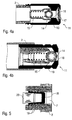
- FIG. 1 shows a microdispenser 1 according to the invention, which can be used in a dispenser (not shown) to deliver microdrops.
- the microdispenser 1 For receiving a sample liquid, the microdispenser 1 has a sample container 2 in the form of a glass capillary with a volume of 20 ⁇ l, the sample container 2 having a constriction 3 which separates the sample container 2 into a sample reservoir 4 and a working space 5.
- a sponge 6 is arranged, which exerts capillary forces on the sample liquid, which generate a holding negative pressure in the sample reservoir 4, thereby preventing the sample liquid from leaking out of the sample container 2.
- the sample container 2 has a nozzle 7 with a nozzle diameter of 70 ⁇ m, via which microdrops 8 can be dispensed.
- the delivery of the microdroplets 8 is effected by a piezoactuator 9, which surrounds the sample container 2 in the area of the constriction 3 in the manner of a shell and the sample container 2 with an electrical control in the radial and / or longitudinal direction expands or compresses.
- a shock wave is generated in the sample liquid contained in the sample container 2, which is reflected at the constriction 3 and leads to the ejection of the microdrops 8 from the nozzle 7.
- the sample container 2 is completely closed except for the nozzle 7 and is not refillable, so that the microdispenser 1 is designed for a disposable use.
- the microdispenser 1 is thus factory-filled with a given sample liquid and then delivered in the filled state, so that contamination by re-filling are completely closed.
- the nozzle 7 is additionally closed, for example by a stopper, a foil or by wax, to hermetically seal the sample container 2.
- An exemplary embodiment of a plug for closing the nozzle 7 is shown in FIG FIG. 5 and will be described in detail later.
- the microdispenser 1 has a bar code 10 which contains information about the microdispenser 1 (e.g., nozzle diameter, container volume) and the sample liquid contained in the sample container 2 in coded form.
- FIG. 2 illustrated alternative embodiment is largely consistent with the embodiment described above and shown in Figure 1, so to avoid repetition, reference is made largely to the above description, wherein the same reference numerals are used for corresponding components or elements.
- a special feature of this embodiment is that the sample container 2 is not hermetically sealed, but has a valve 11.
- the valve 11 allows for a ventilation of the sample container 2 during dispensing, so that the delivery of the microdrops 8 is not hindered by the build-up of a vacuum in the sample container 2.
- the valve 11 allows a refilling of the sample container 2, which allows a reusable use of the microdispenser 1.
- the valve 11 is structurally integrated into the microdispenser and can be closed, so that no sample liquid can escape from the filled sample container 2 during transport and storage of the microdispenser 1.
- FIGS. 4a and 4b Various embodiments of the valve 11 are shown, which will be described in detail later.
- FIG. 3 shows a further embodiment of a microdispenser 1 according to the invention, which in turn largely coincides with the embodiments described above, so that reference is largely made to avoid repetition of the above description, wherein the same reference numerals are used for corresponding components.
- sample container 2 instead of the bottleneck 3 has a cross-sectional widening 12, which also takes place a reflection of shock waves, as in the aforementioned thesis of Wolfgang Wehl: ,, acoustics and fluid mechanics in channels and nozzles of Ink typewriters "is explained.
- FIG. 4a shows a cross-sectional view of an embodiment of the valve 11 with a plastic valve housing 13, which is shrunk onto the sample container 2 and then firmly and gas-tightly connected to the sample container 2 is.
- the slightly undersized valve housing 13 is heated and then pushed onto the sample container 2 in the heated and thus expanded state.
- the valve housing 13 contracts again, which leads to a tight fit of the valve housing 13 on the sample container 2.
- valve housing 13 is connected by an adhesive bond with the sample container 2.
- valve housing 13 a valve ball 14 is pressed by a coil spring 15 against a valve seat 16.
- the valve 11 thus opens only in one direction, when the pressure acting from the outside differential pressure is sufficiently large to lift the valve ball 14 against the force of the coil spring 15 from the valve seat 16.
- the bias and the spring stiffness of the coil spring 15 are in this case selected so that the valve 11 slowly opens in a control of the piezoelectric actuator 9 and increasing emptying of the sample container 2 to ventilate the sample container 2.
- valve 11 in this embodiment a sieve 17 (or a membrane), which prevents the entry of foreign bodies in the sample container 2 when filling the sample container 2.
- FIG. 4b shows an alternative embodiment of the valve 11, which is largely consistent with the embodiment described above, so that to avoid repetition largely to the above description FIG. 4a is referenced, wherein the same reference numerals are used for corresponding components.
- sample container 2 is shrunk onto the valve housing 13 during assembly.
- the sample container 2 which is manufactured with a slight undersize, is heated and then pushed onto the valve housing 13 in the heated and thus expanded state. During the subsequent cooling to the ambient temperature, the sample container 2 then contracts again, which leads to a tight fit of the sample container 2 on the valve housing 13.
- FIG. 5 a cross-sectional view of a plug 18 which can be pressed into the nozzle 7 of the sample container 2 in order to prevent sample liquid from escaping from the sample container 2 during storage or transport.
- the plug 18 is made of plastic and is slightly tapered, which facilitates the insertion of the plug 18 in the nozzle 7.
- the plug 18 has a plurality of annular sealing ribs 19, whereby the surface pressure between the plug 18 and the inside of the nozzle 7 increases and thus the sealing effect is improved.
- the plug 18 is cup-shaped and open to the outside, so that the plug 18 can be pressed by means of a punch 20 into the nozzle 7 into it.
- FIG. 6 illustrated alternative embodiment is largely consistent with the embodiments described above FIG. 1 and FIG. 3 to avoid repetition, reference is made largely to the above description, wherein the same reference numerals are used for corresponding components or elements.
- This embodiment combines the closed structure according to the embodiment FIG. 1 with the cross-sectional widening in the embodiment according to FIG. 3.
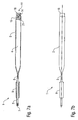
- FIGS. 7a and 7b show a further embodiment of a microdispenser 1 according to the invention, which in turn largely coincides with the embodiments described above, so that reference is largely made to avoid repetition of the above description, wherein the same reference numerals are used for corresponding components.
- sample reservoir 4 has a significantly larger diameter than the working space 5 of the sample container 2. Accordingly, the sample reservoir also has a larger volume than the working space 5. This offers the advantage that the microdispenser 1 successively a plurality of can deliver more than a million microdrops 8, without an interim refilling of the microdispenser is required.
- the nozzle 7 is formed by a nozzle plug, which is pressed into a corresponding opening in the working space 5.
- the geometry of the nozzle is thus not determined by the shape of the opening in the working space 5, which opens up a greater structural design freedom in the design of the nozzle geometry.
- microdispenser 1 in this embodiment a special construction of the valve 11 with the Valve ball 14, the valve seat 16 and a plug 21, wherein the coil spring 15 is internally supported on the plug 21 and the coil spring 15 presses into the valve seat 16.
- the piezoactuator 9 is disposed completely in the region of the working space 5, i. on the nozzle side of the bottleneck 3.
- FIGS. 8a to 8d show a further embodiment of a Mikrodispensers 1 according to the invention, which in turn largely with the above-described and in the FIGS. 7a and 7b illustrated embodiment, so to avoid repetition, reference is made largely to the above description, wherein the same reference numerals are used for corresponding components.
- a special feature of this embodiment is that the nozzle 7 is formed by a nozzle cap 22 which is plugged onto the front end of the working space 5 and has a nozzle opening in its end face.
- the geometry of the nozzle is thus not determined by the shape of the opening in the working space 5, which opens up a greater structural design freedom in the design of the nozzle geometry.
- FIGS. 9a to 9c show a further embodiment of a Mikrodispensers 1 according to the invention, which in turn largely with the above-described and in the FIGS. 7a and 7b illustrated embodiment, so to avoid repetition, reference is made largely to the above description, wherein the same reference numerals are used for corresponding components.
- the nozzle 7 is formed by a nozzle foil 23 which is glued or welded onto the front end of the working space 5 and has a nozzle opening in the center.
- the nozzle geometry is thus also not determined by the shape of the opening in the working space 5, which opens up a greater structural design freedom in the design of the nozzle geometry.
- FIGS. 10a to 10e show a further embodiment of a Mikrodispensers 1 according to the invention, which in turn largely with the above-described and in the FIGS. 7a and 7b illustrated embodiment, so to avoid repetition, reference is made largely to the above description, wherein the same reference numerals are used for corresponding components.
- a special feature of this embodiment is that the nozzle 7 is closed by a closure film 24, which prevents during storage and transport of the microdispenser that can escape through the nozzle 7 sample liquid from the sample container 2. Before dispensing, the closure film 24 is then simply removed from the nozzle 7, wherein the removal of the closure film 24 is facilitated by the nozzle 7 by laterally protruding grip tabs.
- FIGS. 11a and 11c show a further embodiment of a microdispenser 1 according to the invention, which in turn largely coincides with the embodiments described above, so that reference is largely made to avoid repetition of the above description, wherein the same reference numerals are used for corresponding components.
- a special feature of this embodiment is that the piezoelectric actuator 9 is axially attached to the sample container 2, wherein the piezoelectric actuator 9 abuts an annular circumferential stop.
- a mounting sleeve 25 is provided, which is mounted axially on the piezoelectric actuator 9 and on both sides each having an axially extending slot, which allows a slight radial expansion of the mounting sleeve 25, thereby facilitating the attachment of the mounting sleeve 25 becomes. After attaching the mounting sleeve 25, this is mechanically fixed by a securing ring 26.
Landscapes
- General Health & Medical Sciences (AREA)
- Health & Medical Sciences (AREA)
- Life Sciences & Earth Sciences (AREA)
- Chemical & Material Sciences (AREA)
- Analytical Chemistry (AREA)
- Biochemistry (AREA)
- Physics & Mathematics (AREA)
- General Physics & Mathematics (AREA)
- Immunology (AREA)
- Pathology (AREA)
- Sampling And Sample Adjustment (AREA)
- Automatic Analysis And Handling Materials Therefor (AREA)
- Preparation Of Compounds By Using Micro-Organisms (AREA)
Claims (39)
- Microdistributeur (1), pouvant s'insérer dans un appareil de distribution pour distribuer un échantillon liquide, comprenanta) un récipient pour échantillon (2) pour recevoir l'échantillon liquide, etb) une buse (7) pour délivrer sous forme de microgouttelettes l'échantillon qui se trouve dans le récipient pour échantillon (2),c) dans lequel le microdistributeur (1) peut être stocké avec le récipient pour échantillon (2) rempli, indépendamment et en étant fluidiquement séparé de l'appareil de distribution, sans que l'échantillon ne s'échappe du récipient pour échantillon (2) pendant le stockage,d) alors que le récipient pour échantillon (2) présente un réservoir d'échantillons (4) intégré afin de pouvoir délivrer plusieurs échantillons les uns après les autres sans recharge,
caractérisé en ce quee) le microdistributeur est complètement fermé pendant le transport et le stockage, de sorte qu'après une opération de distribution, le microdistributeur (1) peut être remis en stock sans que le liquide d'échantillon ne s'échappe du récipient pour échantillon (2) pendant le stockage. - Microdistributeur selon la revendication 1, caractérisé par une conception destinée à un usage unique, dans lequel le récipient pour échantillon (2) n'est pas rechargeable.
- Microdistributeur selon l'une quelconque des revendications précédentes, caractérisé en ce que le récipient pour échantillon (2) est complètement fermé à l'exception de la buse (7) et ne présente aucune ouverture excepté la buse (7).
- Microdistributeur selon l'une quelconque des revendications 1 ou 2, caractérisé par une vanne (11) pour aérer le récipient pour échantillon (2) lors de la distribution et/ou du remplissage du récipient pour échantillon (2).
- Microdistributeur selon la revendication 4, caractérisé en ce que la vanne (11) est reliée au récipient pour échantillon (2) par un assemblage par retrait ou par collage.
- Microdistributeur selon l'une quelconque des revendications précédentes, caractérisé par un marquage (10) contenant des informations concernant le microdistributeur (1) et/ou l'échantillon se trouvant dans le récipient pour échantillon (2).
- Microdistributeur selon la revendication 6, caractérisé en ce que le marquage (10) est un code optique, en particulier un code à barres unidimensionnel ou bidimensionnel, ou un transpondeur.
- Microdistributeur selon la revendication 7, caractérisé en ce que le transpondeur présente une première zone de mémoire et une deuxième zone de mémoire, dans lequel la première zone de mémoire peut être lue uniquement lorsque la deuxième zone de mémoire est également réinscriptible.
- Microdistributeur selon l'une quelconque des revendications précédentes, caractérisé en ce que dans le récipient pour échantillon (2) est disposée une éponge (6) générant une dépression de maintien dans le récipient pour échantillon (2) par l'intermédiaire des forces capillaires agissant sur l'échantillon liquide.
- Microdistributeur selon l'une quelconque des revendications précédentes, caractérisé en ce que le récipient pour échantillon (2) présente à l'intérieur un saut de section transversale (3, 12).
- Microdistributeur selon la revendication 10, caractérisé en ce que le saut de section transversale (3, 12) est soit un étranglement (3) soit un élargissement de section transversale (12).
- Microdistributeur selon l'une quelconque des revendications précédentes, caractérisé en ce que le récipient pour échantillon (2) et/ou la buse (7) se compose de matière plastique ou de verre ou de céramique.
- Microdistributeur selon l'une quelconque des revendications précédentes, caractérisé par un actionneur (9) pour expulser à travers la buse (7) l'échantillon se trouvant dans le récipient pour échantillon (2).
- Microdistributeur selon la revendication 13, caractérisé en ce que l'actionneur (9) est par construction intégré dans le microdistributeur (1).
- Microdistributeur selon la revendication 13, caractérisé en ce que l'actionneur (9) est par construction séparé du microdistributeur (1).
- Microdistributeur selon l'une quelconque des revendications précédentes, caractérisé en ce que l'actionneur (9) est relié au récipient pour échantillon (2) par contact de matière, par friction et/ou par complémentarité de forme.
- Microdistributeur selon l'une quelconque des revendications 13 à 16, caractérisé en ce que l'actionneur (9) est un actionneur piézoélectrique.
- Microdistributeur selon l'une quelconque des revendications précédentes, caractérisé en ce que l'actionneur (9) comprime et/ou dilate le récipient pour échantillon (2) à l'extérieur en forme de douille lors d'une excitation électrique de l'actionneur (9).
- Microdistributeur selon l'une quelconque des revendications précédentes, caractérisé en ce que l'actionneur (9) est fixé sur le récipient pour échantillon (2) par une douille de montage (25).
- Microdistributeur selon la revendication 19, caractérisé en ce que la douille de montage (25) présente une fente élastique s'étendant axialement.
- Microdistributeur selon la revendication 19 ou 20, caractérisé en ce que la douille de montage (25) est fixée sur le récipient pour échantillon (2) par un vissage ou par un circlip (26).
- Microdistributeur selon l'une quelconque des revendications précédentes, caractérisé en ce que la buse (7) et/ou le récipient pour échantillon (2) est muni(e) d'un revêtement, dans lequel le revêtement a de préférence un effet d'immobilisation des protéines et d'immobilisation de l'ADN, permet une adsorption spécifique de biomolécules, empêche une coagulation d'un échantillon versé et/ou convient à la purification et/ou la concentration de l'échantillon.
- Microdistributeur selon l'une quelconque des revendications précédentes, caractérisé en ce que la buse (7) est fermée en vue du stockage.
- Microdistributeur selon la revendication 23, caractérisé en ce qu'en vue du stockage, la buse (7) est fermée par un bouchon (18), un film de scellement (24), de la cire ou un capuchon.
- Microdistributeur selon l'une quelconque des revendications précédentes, caractérisé en ce que le récipient pour échantillon (2) présente un volume dans la plage de 1 nl à 1 ml.
- Microdistributeur selon l'une quelconque des revendications précédentes, caractérisé en ce que la buse (7) présente un diamètre de buse dans la plage de 10 µm à 100 µm.
- Microdistributeur selon l'une quelconque des revendications précédentes, caractérisé en ce que le récipient pour échantillon (2) présente en plus du réservoir d'échantillon (4) un espace utile (5) qui est séparé du réservoir d'échantillon (4) par un étranglement (3), dans lequel le réservoir d'échantillon (4) présente un plus grand volume que l'espace utile (5).
- Microdistributeur selon l'une quelconque des revendications précédentes, caractérisé en ce que la buse (7) est formée par un film de buse (23) ou un capuchon de buse (22) ou un bouchon de buse.
- Appareil de distribution avec au moins un microdistributeur (1) selon l'une quelconque des revendications 13 à 28, dans lequel l'appareil de distribution provoque l'excitation de l'actionneur (9) pour délivrer des gouttelettes.
- Appareil de distribution selon la revendication 29, caractérisé en ce qu'aucune amenée d'échantillon n'est prévue pour le microdistributeur (1).
- Procédé d'utilisation pour un microdistributeur (1) selon la revendication 1, présentant un récipient pour échantillon (2) pour recevoir un échantillon liquide et une buse (7) pour délivrer l'échantillon sous la forme de microgouttelettes, dans lequel le microdistributeur (1) avec le récipient pour échantillon (2) contenant l'échantillon liquide est stocké séparément d'un appareil de distribution, caractérisé en ce que le microdistributeur (1) est complètement fermé pendant le transport et le stockage de sorte que le microdistributeur (1) est remis en stock après une opération de distribution, dans lequel pendant le stockage, aucun liquide d'échantillon ne s'échappe du récipient pour échantillon (2).
- Procédé d'utilisation selon la revendication 31, caractérisé en ce que le récipient pour échantillon (2) n'est pas rechargé et le microdistributeur (1) est jeté après une ou plusieurs opérations de distribution.
- Procédé d'utilisation selon l'une quelconque des revendications 31 à 32, caractérisé en ce qu'à partir d'un marquage (10) appliqué sur le microdistributeur (1), des informations concernant le microdistributeur (1) et/ou l'échantillon se trouvant dans le récipient pour échantillon (2) sont lues.
- Procédé d'utilisation selon la revendication 33, caractérisé en ce que- les informations sont lues à partir du marquage (10) pendant le stockage du microdistributeur (1), et- le microdistributeur (1) est sorti du stock ou reste en stock en fonction des informations lues.
- Procédé d'utilisation selon l'une quelconque des revendications 31 à 34, caractérisé en ce que la buse (7) est fermée avant le stockage et ouverte après le stockage.
- Procédé d'utilisation selon l'une quelconque des revendications 31 à 35, caractérisé en ce que le récipient pour échantillon (2) est rempli avec l'échantillon liquide par l'intermédiaire de la buse (7) par un effet de capillarité.
- Procédé d'utilisation selon la revendication 31 ou 36, caractérisé en ce que le récipient pour échantillon (2) est aéré lors de la distribution au moyen d'une vanne (11).
- Procédé d'utilisation selon la revendication 37, caractérisé en ce que le récipient pour échantillon (2) est rempli avec l'échantillon liquide par l'intermédiaire de la vanne (11).
- Procédé d'utilisation selon l'une quelconque des revendications 31 à 38, caractérisé en ce qu'une purification et/ou concentration de l'échantillon est/sont prévue(s) à l'aide d'un revêtement spécifique de la buse (7) et/ou du récipient pour échantillon (2).
Applications Claiming Priority (2)
| Application Number | Priority Date | Filing Date | Title |
|---|---|---|---|
| DE102005025640A DE102005025640A1 (de) | 2005-06-03 | 2005-06-03 | Mikrodispenser und zugehöriges Betriebsverfahren |
| PCT/EP2006/005114 WO2006128662A1 (fr) | 2005-06-03 | 2006-05-29 | Microdistributeur et procede correspondant pour l'utiliser |
Publications (2)
| Publication Number | Publication Date |
|---|---|
| EP1886146A1 EP1886146A1 (fr) | 2008-02-13 |
| EP1886146B1 true EP1886146B1 (fr) | 2011-04-06 |
Family
ID=36763811
Family Applications (1)
| Application Number | Title | Priority Date | Filing Date |
|---|---|---|---|
| EP06753953A Not-in-force EP1886146B1 (fr) | 2005-06-03 | 2006-05-29 | Microdistributeur et procede correspondant pour l'utiliser |
Country Status (5)
| Country | Link |
|---|---|
| US (2) | US8273307B2 (fr) |
| EP (1) | EP1886146B1 (fr) |
| AT (1) | ATE504838T1 (fr) |
| DE (2) | DE102005025640A1 (fr) |
| WO (1) | WO2006128662A1 (fr) |
Families Citing this family (31)
| Publication number | Priority date | Publication date | Assignee | Title |
|---|---|---|---|---|
| EP1766417B1 (fr) | 2004-06-14 | 2013-04-03 | Parker-Hannifin Corporation | Systeme et procede de manipulation robotique a outils detachables fonctionnant separement |
| WO2006083695A2 (fr) | 2005-01-28 | 2006-08-10 | Parker-Hannifin Corporation | Sonde d'echantillonnage, dispositif de prehension et interface de systemes de gestion d'echantillons de laboratoire |
| US8192698B2 (en) | 2006-01-27 | 2012-06-05 | Parker-Hannifin Corporation | Sampling probe, gripper and interface for laboratory sample management systems |
| DE102008045423A1 (de) | 2008-09-02 | 2010-03-04 | Scienion Ag | Druckstellglied, insbesondere Belüftungsventil zur Belüftung eines Mikrodispensers |
| JP2012510065A (ja) * | 2008-11-28 | 2012-04-26 | ハミルトン・ボナドゥーツ・アーゲー | 極小の測定体積の測定に適した測定デバイス、及び測定方法 |
| EP2613889B1 (fr) * | 2010-09-07 | 2017-09-20 | University of Limerick | Distributeur de gouttelettes de liquide |
| EP2665557B1 (fr) * | 2011-01-21 | 2020-01-01 | Biodot, Inc. | Distributeur piézoélectrique à capteur longitudinal et tube capillaire remplaçable |
| FR2980535B1 (fr) * | 2011-09-22 | 2018-03-09 | Commissariat A L'energie Atomique Et Aux Energies Alternatives | Pompe d'injection d'un fluide, et notamment micropompe utilisable pour delivrer une dose determinee |
| US10180442B2 (en) * | 2014-03-12 | 2019-01-15 | Dna Medicine Institute, Inc. | Sample consumable and loader |
| CN113230021A (zh) * | 2015-01-12 | 2021-08-10 | 科达莱昂治疗公司 | 微滴递送设备和方法 |
| JP2018515153A (ja) | 2015-04-10 | 2018-06-14 | ケダリオン セラピューティックス,インコーポレイテッド | 交換式アンプルを備えた圧電式ディスペンサ |
| DE102015011970B4 (de) | 2015-09-09 | 2017-04-06 | Scienion Ag | Dispensiergerät und entsprechendes Dispensierverfahren |
| CN105032717B (zh) * | 2015-09-18 | 2017-10-17 | 京东方科技集团股份有限公司 | 一种封框胶涂布喷嘴及封框胶涂布装置 |
| KR102412086B1 (ko) | 2017-01-20 | 2022-06-22 | 켄달리온 테라퓨틱스 인코포레이티드 | 압전 유체 분배기 |
| CN110573880B (zh) | 2017-02-10 | 2023-05-16 | 奎多公司 | 具有受控流体流动通道的基底的横向流动测试 |
| EP3645167A4 (fr) | 2017-06-28 | 2021-02-24 | Bio-rad Laboratories, Inc. | Système et procédé de détection de gouttelette |
| US11045805B2 (en) | 2017-11-01 | 2021-06-29 | Bio-Rad Laboratories, Inc. | Microfluidic system and method for arranging objects |
| WO2019113483A1 (fr) | 2017-12-08 | 2019-06-13 | Kedalion Therapeutics, Inc. | Système d'alignement pour administration de fluide |
| US20190208890A1 (en) * | 2018-01-08 | 2019-07-11 | Ruth Bailey Schow | Eyelash washing device |
| US12350194B1 (en) | 2018-04-12 | 2025-07-08 | Bausch + Lomb Ireland Limited | Topical ocular delivery of fluids with controlled mass dosing and wireless communication |
| US20190314197A1 (en) | 2018-04-12 | 2019-10-17 | Kedalion Therapeutics, Inc. | Topical Ocular Delivery Methods and Devices for Use in the Same |
| CN112074458B (zh) * | 2018-04-27 | 2023-05-23 | 千禧制药公司 | 用于填充容器的系统和方法 |
| WO2020010116A1 (fr) | 2018-07-03 | 2020-01-09 | Kedalion Therapeutics, Inc. | Dispositifs d'administration oculaire topique et leurs procédés d'utilisation |
| US12097145B2 (en) | 2019-03-06 | 2024-09-24 | Bausch + Lomb Ireland Limited | Vented multi-dose ocular fluid delivery system |
| US11679028B2 (en) | 2019-03-06 | 2023-06-20 | Novartis Ag | Multi-dose ocular fluid delivery system |
| US12496218B1 (en) | 2019-11-12 | 2025-12-16 | Bausch + Lomb Ireland Limited | Fractionated topical ocular drug delivery methods and devices for use in the same |
| US12290472B2 (en) | 2020-04-17 | 2025-05-06 | Bausch + Lomb Ireland Limited | Hydrodynamically actuated preservative free dispensing system |
| US12090087B2 (en) | 2020-04-17 | 2024-09-17 | Bausch + Lomb Ireland Limited | Hydrodynamically actuated preservative free dispensing system having a collapsible liquid reservoir |
| US11938057B2 (en) | 2020-04-17 | 2024-03-26 | Bausch + Lomb Ireland Limited | Hydrodynamically actuated preservative free dispensing system |
| CN115768384A (zh) | 2020-04-17 | 2023-03-07 | 科达隆治疗公司 | 流体动力致动的不含防腐剂分配系统 |
| KR102572756B1 (ko) * | 2020-11-20 | 2023-08-30 | 바디텍메드(주) | 모세관 팁 결합용 소켓 |
Citations (4)
| Publication number | Priority date | Publication date | Assignee | Title |
|---|---|---|---|---|
| GB2216259A (en) * | 1988-03-31 | 1989-10-04 | Microvol Ltd | Dispenser for chemical analysis carrying a code |
| EP0900594A2 (fr) * | 1997-09-06 | 1999-03-10 | Schott Glas | Burette à piston pour système de burettage |
| US6092695A (en) * | 1992-05-11 | 2000-07-25 | Cytologix Corporation | Interchangeable liquid dispensing cartridge pump |
| WO2003054518A1 (fr) * | 2001-12-11 | 2003-07-03 | Astrazeneca Ab | Machine et procede de traitement de biomolecules |
Family Cites Families (48)
| Publication number | Priority date | Publication date | Assignee | Title |
|---|---|---|---|---|
| US2692503A (en) * | 1952-07-09 | 1954-10-26 | Owens Illinois Glass Co | Pipette |
| USRE30845E (en) * | 1972-02-29 | 1982-01-12 | Roussel-Uclaf | Apparatus for automatically measuring the light transmission factor or liquid test samples |
| DE2653051A1 (de) * | 1976-11-23 | 1978-05-24 | Werner Bauser | Pipette fuer medizinisch und oder industrielle anwendung |
| US4162030A (en) | 1977-04-20 | 1979-07-24 | J. Claybrook Lewis and Associates, Ltd. | Disposable package dispenser having a pressure release channel |
| NL8102227A (nl) * | 1981-05-07 | 1982-12-01 | Philips Nv | Werkwijze voor het vervaardigen van straalpijpkanalen en inktstraaldrukker met een volgens die werkwijze vervaardigd straalpijpkanaal. |
| FR2513376A1 (fr) * | 1981-09-23 | 1983-03-25 | Jean Bajard | Dispositif de pipetage automatique |
| IT1157118B (it) * | 1982-12-03 | 1987-02-11 | Olivetti & Co Spa | Dispositivo stampante a getto di inchiostro |
| IT1157119B (it) * | 1982-12-03 | 1987-02-11 | Olivetti & Co Spa | Dispositivo stampante a getto di inchiostro |
| DE4024545A1 (de) | 1990-08-02 | 1992-02-06 | Boehringer Mannheim Gmbh | Verfahren und vorrichtung zum dosierten zufuehren einer biochemischen analysefluessigkeit auf ein target |
| US5525302A (en) * | 1991-02-01 | 1996-06-11 | Astle; Thomas W. | Method and device for simultaneously transferring plural samples |
| EP0587951B1 (fr) | 1992-09-18 | 1997-12-17 | AMERSHAM INTERNATIONAL plc | Méthode pour capturer les noyaux cellulaires et dispositif utilisé pour cela |
| US5438127A (en) | 1993-09-27 | 1995-08-01 | Becton Dickinson And Company | DNA purification by solid phase extraction using a PCl3 modified glass fiber membrane |
| DE4447015C2 (de) | 1994-12-30 | 1997-09-11 | Invitek Gmbh | Verfahren zur schnellen Isolierung und ggf. Lagerung von Ribonukleinsäuren |
| US6037465A (en) | 1994-06-14 | 2000-03-14 | Invitek Gmbh | Universal process for isolating and purifying nucleic acids from extremely small amounts of highly contaminated various starting materials |
| US5705628A (en) | 1994-09-20 | 1998-01-06 | Whitehead Institute For Biomedical Research | DNA purification and isolation using magnetic particles |
| KR100306951B1 (ko) | 1995-12-05 | 2001-11-15 | 테칸 보스턴, 인코포레이티드 | 내장된정보과학에의해미세유체공학시스템내의유체유동을구동시키기위해구심가속도를이용하는장치및방법 |
| DE29601618U1 (de) | 1996-01-31 | 1996-07-04 | InViTek GmbH, 13125 Berlin | Vorrichtung zur gleichzeitigen multiplen Isolierung |
| CA2200030C (fr) * | 1996-03-15 | 2006-04-25 | Seiji Ohtani | Seringue |
| US6074609A (en) * | 1996-04-24 | 2000-06-13 | Glaxo Wellcome Inc. | Systems for arraying beads |
| US5958342A (en) * | 1996-05-17 | 1999-09-28 | Incyte Pharmaceuticals, Inc. | Jet droplet device |
| US6101946A (en) * | 1997-11-21 | 2000-08-15 | Telechem International Inc. | Microarray printing device including printing pins with flat tips and exterior channel and method of manufacture |
| DE19754000A1 (de) * | 1997-12-05 | 1999-06-17 | Max Planck Gesellschaft | Vorrichtung und Verfahren zur elektrisch ausgelösten Mikrotropfenabgabe mit einem Dispensierkopf |
| GB9800933D0 (en) * | 1998-01-17 | 1998-03-11 | Central Research Lab Ltd | A dispenser |
| DE19823719B4 (de) * | 1998-05-27 | 2011-12-15 | MAX-PLANCK-Gesellschaft zur Förderung der Wissenschaften e.V. | Verfahren zum Aufkonzentrieren von Substanzen |
| US6296811B1 (en) * | 1998-12-10 | 2001-10-02 | Aurora Biosciences Corporation | Fluid dispenser and dispensing methods |
| US6232129B1 (en) * | 1999-02-03 | 2001-05-15 | Peter Wiktor | Piezoelectric pipetting device |
| US6554792B2 (en) * | 1999-05-21 | 2003-04-29 | Mallinckrodt Inc. | Suspension device and method |
| GB2355717A (en) | 1999-10-28 | 2001-05-02 | Amersham Pharm Biotech Uk Ltd | DNA isolation method |
| DE50112157D1 (de) * | 2000-01-11 | 2007-04-19 | Roland Bodmeier | Kit zur implantation enthaltend eine trägerphase und ein lösungsmittel |
| US20020064482A1 (en) * | 2000-02-02 | 2002-05-30 | Tisone Thomas C. | Method and apparatus for developing DNA microarrays |
| US6537502B1 (en) * | 2000-07-25 | 2003-03-25 | Harvard Apparatus, Inc. | Surface coated housing for sample preparation |
| CH695544A5 (de) * | 2000-11-17 | 2006-06-30 | Tecan Trading Ag | Vorrichtung zur Abgabe bzw. Aufnahme/Abgabe von Flüssigkeitsproben. |
| US6343717B1 (en) | 2000-11-21 | 2002-02-05 | Jack Yongfeng Zhang | Pre-filled disposable pipettes |
| DE10106362B4 (de) * | 2001-02-12 | 2005-03-17 | Licht, Michael, Dipl.-Ing. (FH) | Vorrichtung und Verfahren zum Sammeln von wässrigen Flüssigkeitsproben |
| US6467888B2 (en) * | 2001-02-21 | 2002-10-22 | Illinois Tool Works Inc. | Intelligent fluid delivery system for a fluid jet printing system |
| US20020164808A1 (en) * | 2001-05-03 | 2002-11-07 | Hideki Itaya | Diagnostic pipette assembly including apparatus for automated aspiration |
| US20030007897A1 (en) * | 2001-07-06 | 2003-01-09 | Andrew Creasey | Pipette tips |
| US6579724B2 (en) * | 2001-09-13 | 2003-06-17 | First Ten Angstroms | Dispensing method and apparatus for dispensing very small quantities of fluid |
| US6457612B1 (en) | 2001-10-12 | 2002-10-01 | Amphastar Pharmaceuticals Inc. | Sealable and manipulable pre-filled disposable pipette |
| US6866825B2 (en) | 2001-11-05 | 2005-03-15 | Industrial Technology Research Institute | Micro-dispenser for biochemical analysis |
| WO2003048786A2 (fr) * | 2001-11-30 | 2003-06-12 | Bristol-Myers Squibb Company | Configurations de pipettes et jeux de pipettes pour mesurer des proprietes electriques cellulaires |
| US6780381B2 (en) * | 2002-04-08 | 2004-08-24 | Felix H. Yiu | Pipettor and externally sealed pipette tip |
| DE10309211A1 (de) * | 2003-02-28 | 2004-09-09 | Leica Mikrosysteme Gmbh | Vorrichtung und Verfahren zur immunologischen Markierung für Gewebedünnschnitte |
| EP1618060A4 (fr) * | 2003-04-30 | 2007-03-21 | Aurora Discovery Inc | Procede et systeme de distribution precise d'un liquide |
| US7695688B2 (en) * | 2003-09-19 | 2010-04-13 | Applied Biosystems, Llc | High density plate filler |
| EP1738179B1 (fr) * | 2004-04-20 | 2007-10-24 | Tecan Trading AG | Dispositif pour transporter ou examiner des liquides |
| US7955865B2 (en) * | 2004-06-09 | 2011-06-07 | The University Of British Columbia | Reagent delivery apparatus and methods |
| US7618576B2 (en) * | 2004-11-12 | 2009-11-17 | Phoenix S&T, Inc. | Microfluidic array devices and methods of manufacture thereof |
-
2005
- 2005-06-03 DE DE102005025640A patent/DE102005025640A1/de not_active Ceased
-
2006
- 2006-05-29 DE DE502006009256T patent/DE502006009256D1/de active Active
- 2006-05-29 AT AT06753953T patent/ATE504838T1/de active
- 2006-05-29 US US11/720,265 patent/US8273307B2/en not_active Expired - Fee Related
- 2006-05-29 EP EP06753953A patent/EP1886146B1/fr not_active Not-in-force
- 2006-05-29 WO PCT/EP2006/005114 patent/WO2006128662A1/fr not_active Ceased
-
2012
- 2012-08-22 US US13/591,917 patent/US20120312836A1/en not_active Abandoned
Patent Citations (4)
| Publication number | Priority date | Publication date | Assignee | Title |
|---|---|---|---|---|
| GB2216259A (en) * | 1988-03-31 | 1989-10-04 | Microvol Ltd | Dispenser for chemical analysis carrying a code |
| US6092695A (en) * | 1992-05-11 | 2000-07-25 | Cytologix Corporation | Interchangeable liquid dispensing cartridge pump |
| EP0900594A2 (fr) * | 1997-09-06 | 1999-03-10 | Schott Glas | Burette à piston pour système de burettage |
| WO2003054518A1 (fr) * | 2001-12-11 | 2003-07-03 | Astrazeneca Ab | Machine et procede de traitement de biomolecules |
Also Published As
| Publication number | Publication date |
|---|---|
| ATE504838T1 (de) | 2011-04-15 |
| DE102005025640A1 (de) | 2006-12-07 |
| EP1886146A1 (fr) | 2008-02-13 |
| DE502006009256D1 (de) | 2011-05-19 |
| US8273307B2 (en) | 2012-09-25 |
| WO2006128662A1 (fr) | 2006-12-07 |
| US20120312836A1 (en) | 2012-12-13 |
| US20090060793A1 (en) | 2009-03-05 |
Similar Documents
| Publication | Publication Date | Title |
|---|---|---|
| EP1886146B1 (fr) | Microdistributeur et procede correspondant pour l'utiliser | |
| DE69935262T2 (de) | Vorrichtung zum abgeben von Flüssigkeit und Abgabemethoden | |
| DE19933458B4 (de) | Einrichtungen und Systeme zum Handhaben von Flüssigkeitsproben | |
| DE60317305T2 (de) | Kontaktloses verfahren zur verteilung geringer flüssigkeitsmengen | |
| DE69931787T2 (de) | Vorrichtung und Verfahren zur Verabreichung von Tropfen | |
| DE69714269T2 (de) | Patrone und system zum speichern und verteilen von reagenzien | |
| DE102018111822B4 (de) | Fluidisches System zur Aufnahme, Abgabe und Bewegung von Flüssigkeiten, Verfahren zur Verarbeitung von Fluiden in einem fluidischen System | |
| DE69925210T2 (de) | Spitze für eine Saugvorrichtung | |
| DE60008863T2 (de) | Dispensiergerät mit hochdruck-puls-auslösemechanismus | |
| EP1333925A1 (fr) | Dispositif permettant de prelever et/ou de distribuer des echantillons de liquide | |
| EP1745851A1 (fr) | Procede, dispositif et programme pour la classification des liquides | |
| EP3120929A1 (fr) | Soupape d'admission pour systemes de chambres et recipients a echantillons ainsi que systemes de chambres dotes de recipients a echantillons dotes de telles soupapes d'admission | |
| EP1699560B1 (fr) | Pointe de pipette, systeme de pipette, dispositif d'actionnement de pipette et procede de pipettage dans la plage du nanolitre | |
| DE102011005957A1 (de) | System zu Behandlung von Flüssigkeiten | |
| DE102010030489A1 (de) | System zu Behandlung von Flüssigkeiten | |
| EP3189897B1 (fr) | Mécanisme d'éjection pour points de pipette | |
| EP1333926A1 (fr) | Dispositif et systeme de distribution ou d'absorption/distribution d'echantillons de liquide | |
| DE10135963B4 (de) | Vorrichtung zum Pipettieren einer Flüssigkeit | |
| EP1641564B1 (fr) | Utilisation d'un contenant a usage unique, dispositif microfluidique et procede de traitement de molecules | |
| DE202006019795U1 (de) | Mikrodispenser | |
| EP3624927B1 (fr) | Module de filtration à usage unique ou module de nettoyage à usage unique, pouvant être utilisés respectivement pour un système de filtration modulaire | |
| EP0187167A1 (fr) | Appareil doseur pour liquides | |
| EP3485974B1 (fr) | Dispositif de microdosage permettant le dosage de plus petits échantillons de fluide | |
| DE19742005A1 (de) | Vorrichtung und Verfahren zum genauen Dosieren und Umsetzen von kleinen Flüssigkeitsmengen | |
| WO2001059424A1 (fr) | Procede et dispositif pour collecter des fractions apres une separation de substances |
Legal Events
| Date | Code | Title | Description |
|---|---|---|---|
| PUAI | Public reference made under article 153(3) epc to a published international application that has entered the european phase |
Free format text: ORIGINAL CODE: 0009012 |
|
| 17P | Request for examination filed |
Effective date: 20071114 |
|
| AK | Designated contracting states |
Kind code of ref document: A1 Designated state(s): AT BE BG CH CY CZ DE DK EE ES FI FR GB GR HU IE IS IT LI LT LU LV MC NL PL PT RO SE SI SK TR |
|
| DAX | Request for extension of the european patent (deleted) | ||
| 17Q | First examination report despatched |
Effective date: 20080917 |
|
| GRAP | Despatch of communication of intention to grant a patent |
Free format text: ORIGINAL CODE: EPIDOSNIGR1 |
|
| GRAS | Grant fee paid |
Free format text: ORIGINAL CODE: EPIDOSNIGR3 |
|
| GRAA | (expected) grant |
Free format text: ORIGINAL CODE: 0009210 |
|
| AK | Designated contracting states |
Kind code of ref document: B1 Designated state(s): AT BE BG CH CY CZ DE DK EE ES FI FR GB GR HU IE IS IT LI LT LU LV MC NL PL PT RO SE SI SK TR |
|
| REG | Reference to a national code |
Ref country code: GB Ref legal event code: FG4D Free format text: NOT ENGLISH |
|
| REG | Reference to a national code |
Ref country code: CH Ref legal event code: EP |
|
| REG | Reference to a national code |
Ref country code: IE Ref legal event code: FG4D |
|
| REF | Corresponds to: |
Ref document number: 502006009256 Country of ref document: DE Date of ref document: 20110519 Kind code of ref document: P |
|
| REG | Reference to a national code |
Ref country code: DE Ref legal event code: R096 Ref document number: 502006009256 Country of ref document: DE Effective date: 20110519 |
|
| REG | Reference to a national code |
Ref country code: CH Ref legal event code: NV Representative=s name: RITSCHER & PARTNER AG |
|
| REG | Reference to a national code |
Ref country code: NL Ref legal event code: T3 |
|
| PG25 | Lapsed in a contracting state [announced via postgrant information from national office to epo] |
Ref country code: SI Free format text: LAPSE BECAUSE OF FAILURE TO SUBMIT A TRANSLATION OF THE DESCRIPTION OR TO PAY THE FEE WITHIN THE PRESCRIBED TIME-LIMIT Effective date: 20110406 |
|
| LTIE | Lt: invalidation of european patent or patent extension |
Effective date: 20110406 |
|
| REG | Reference to a national code |
Ref country code: IE Ref legal event code: FD4D |
|
| PG25 | Lapsed in a contracting state [announced via postgrant information from national office to epo] |
Ref country code: PT Free format text: LAPSE BECAUSE OF FAILURE TO SUBMIT A TRANSLATION OF THE DESCRIPTION OR TO PAY THE FEE WITHIN THE PRESCRIBED TIME-LIMIT Effective date: 20110808 Ref country code: SE Free format text: LAPSE BECAUSE OF FAILURE TO SUBMIT A TRANSLATION OF THE DESCRIPTION OR TO PAY THE FEE WITHIN THE PRESCRIBED TIME-LIMIT Effective date: 20110406 Ref country code: LT Free format text: LAPSE BECAUSE OF FAILURE TO SUBMIT A TRANSLATION OF THE DESCRIPTION OR TO PAY THE FEE WITHIN THE PRESCRIBED TIME-LIMIT Effective date: 20110406 |
|
| BERE | Be: lapsed |
Owner name: SCIENION A.G. Effective date: 20110531 |
|
| PG25 | Lapsed in a contracting state [announced via postgrant information from national office to epo] |
Ref country code: FI Free format text: LAPSE BECAUSE OF FAILURE TO SUBMIT A TRANSLATION OF THE DESCRIPTION OR TO PAY THE FEE WITHIN THE PRESCRIBED TIME-LIMIT Effective date: 20110406 Ref country code: GR Free format text: LAPSE BECAUSE OF FAILURE TO SUBMIT A TRANSLATION OF THE DESCRIPTION OR TO PAY THE FEE WITHIN THE PRESCRIBED TIME-LIMIT Effective date: 20110707 Ref country code: CY Free format text: LAPSE BECAUSE OF FAILURE TO SUBMIT A TRANSLATION OF THE DESCRIPTION OR TO PAY THE FEE WITHIN THE PRESCRIBED TIME-LIMIT Effective date: 20110406 Ref country code: ES Free format text: LAPSE BECAUSE OF FAILURE TO SUBMIT A TRANSLATION OF THE DESCRIPTION OR TO PAY THE FEE WITHIN THE PRESCRIBED TIME-LIMIT Effective date: 20110717 Ref country code: IS Free format text: LAPSE BECAUSE OF FAILURE TO SUBMIT A TRANSLATION OF THE DESCRIPTION OR TO PAY THE FEE WITHIN THE PRESCRIBED TIME-LIMIT Effective date: 20110806 Ref country code: LV Free format text: LAPSE BECAUSE OF FAILURE TO SUBMIT A TRANSLATION OF THE DESCRIPTION OR TO PAY THE FEE WITHIN THE PRESCRIBED TIME-LIMIT Effective date: 20110406 |
|
| PG25 | Lapsed in a contracting state [announced via postgrant information from national office to epo] |
Ref country code: MC Free format text: LAPSE BECAUSE OF NON-PAYMENT OF DUE FEES Effective date: 20110531 |
|
| PG25 | Lapsed in a contracting state [announced via postgrant information from national office to epo] |
Ref country code: IE Free format text: LAPSE BECAUSE OF FAILURE TO SUBMIT A TRANSLATION OF THE DESCRIPTION OR TO PAY THE FEE WITHIN THE PRESCRIBED TIME-LIMIT Effective date: 20110406 Ref country code: CZ Free format text: LAPSE BECAUSE OF FAILURE TO SUBMIT A TRANSLATION OF THE DESCRIPTION OR TO PAY THE FEE WITHIN THE PRESCRIBED TIME-LIMIT Effective date: 20110406 Ref country code: EE Free format text: LAPSE BECAUSE OF FAILURE TO SUBMIT A TRANSLATION OF THE DESCRIPTION OR TO PAY THE FEE WITHIN THE PRESCRIBED TIME-LIMIT Effective date: 20110406 |
|
| PLBE | No opposition filed within time limit |
Free format text: ORIGINAL CODE: 0009261 |
|
| STAA | Information on the status of an ep patent application or granted ep patent |
Free format text: STATUS: NO OPPOSITION FILED WITHIN TIME LIMIT |
|
| PG25 | Lapsed in a contracting state [announced via postgrant information from national office to epo] |
Ref country code: RO Free format text: LAPSE BECAUSE OF FAILURE TO SUBMIT A TRANSLATION OF THE DESCRIPTION OR TO PAY THE FEE WITHIN THE PRESCRIBED TIME-LIMIT Effective date: 20110406 Ref country code: SK Free format text: LAPSE BECAUSE OF FAILURE TO SUBMIT A TRANSLATION OF THE DESCRIPTION OR TO PAY THE FEE WITHIN THE PRESCRIBED TIME-LIMIT Effective date: 20110406 Ref country code: PL Free format text: LAPSE BECAUSE OF FAILURE TO SUBMIT A TRANSLATION OF THE DESCRIPTION OR TO PAY THE FEE WITHIN THE PRESCRIBED TIME-LIMIT Effective date: 20110406 Ref country code: DK Free format text: LAPSE BECAUSE OF FAILURE TO SUBMIT A TRANSLATION OF THE DESCRIPTION OR TO PAY THE FEE WITHIN THE PRESCRIBED TIME-LIMIT Effective date: 20110406 |
|
| 26N | No opposition filed |
Effective date: 20120110 |
|
| PG25 | Lapsed in a contracting state [announced via postgrant information from national office to epo] |
Ref country code: BE Free format text: LAPSE BECAUSE OF NON-PAYMENT OF DUE FEES Effective date: 20110531 |
|
| REG | Reference to a national code |
Ref country code: DE Ref legal event code: R097 Ref document number: 502006009256 Country of ref document: DE Effective date: 20120110 |
|
| REG | Reference to a national code |
Ref country code: AT Ref legal event code: MM01 Ref document number: 504838 Country of ref document: AT Kind code of ref document: T Effective date: 20110529 |
|
| PG25 | Lapsed in a contracting state [announced via postgrant information from national office to epo] |
Ref country code: AT Free format text: LAPSE BECAUSE OF NON-PAYMENT OF DUE FEES Effective date: 20110529 |
|
| PG25 | Lapsed in a contracting state [announced via postgrant information from national office to epo] |
Ref country code: LU Free format text: LAPSE BECAUSE OF NON-PAYMENT OF DUE FEES Effective date: 20110529 |
|
| PG25 | Lapsed in a contracting state [announced via postgrant information from national office to epo] |
Ref country code: BG Free format text: LAPSE BECAUSE OF FAILURE TO SUBMIT A TRANSLATION OF THE DESCRIPTION OR TO PAY THE FEE WITHIN THE PRESCRIBED TIME-LIMIT Effective date: 20110706 |
|
| PG25 | Lapsed in a contracting state [announced via postgrant information from national office to epo] |
Ref country code: TR Free format text: LAPSE BECAUSE OF FAILURE TO SUBMIT A TRANSLATION OF THE DESCRIPTION OR TO PAY THE FEE WITHIN THE PRESCRIBED TIME-LIMIT Effective date: 20110406 |
|
| PG25 | Lapsed in a contracting state [announced via postgrant information from national office to epo] |
Ref country code: HU Free format text: LAPSE BECAUSE OF FAILURE TO SUBMIT A TRANSLATION OF THE DESCRIPTION OR TO PAY THE FEE WITHIN THE PRESCRIBED TIME-LIMIT Effective date: 20110406 |
|
| REG | Reference to a national code |
Ref country code: CH Ref legal event code: PFA Owner name: SCIENION AG, DE Free format text: FORMER OWNER: SCIENION AG, DE |
|
| PG25 | Lapsed in a contracting state [announced via postgrant information from national office to epo] |
Ref country code: IT Free format text: LAPSE BECAUSE OF FAILURE TO SUBMIT A TRANSLATION OF THE DESCRIPTION OR TO PAY THE FEE WITHIN THE PRESCRIBED TIME-LIMIT Effective date: 20110406 |
|
| REG | Reference to a national code |
Ref country code: FR Ref legal event code: PLFP Year of fee payment: 11 |
|
| REG | Reference to a national code |
Ref country code: FR Ref legal event code: PLFP Year of fee payment: 12 |
|
| REG | Reference to a national code |
Ref country code: FR Ref legal event code: PLFP Year of fee payment: 13 |
|
| REG | Reference to a national code |
Ref country code: DE Ref legal event code: R082 Ref document number: 502006009256 Country of ref document: DE Representative=s name: V. BEZOLD & PARTNER PATENTANWAELTE - PARTG MBB, DE Ref country code: DE Ref legal event code: R081 Ref document number: 502006009256 Country of ref document: DE Owner name: SCIENION GMBH, DE Free format text: FORMER OWNER: SCIENION AG, 12489 BERLIN, DE |
|
| REG | Reference to a national code |
Ref country code: NL Ref legal event code: PD Owner name: SCIENION GMBH; DE Free format text: DETAILS ASSIGNMENT: CHANGE OF OWNER(S), CHANGE OF LEGAL ENTITY; FORMER OWNER NAME: SCIENION AG Effective date: 20210722 |
|
| PGFP | Annual fee paid to national office [announced via postgrant information from national office to epo] |
Ref country code: NL Payment date: 20220518 Year of fee payment: 17 |
|
| PGFP | Annual fee paid to national office [announced via postgrant information from national office to epo] |
Ref country code: GB Payment date: 20220523 Year of fee payment: 17 Ref country code: FR Payment date: 20220523 Year of fee payment: 17 Ref country code: DE Payment date: 20220610 Year of fee payment: 17 |
|
| PGFP | Annual fee paid to national office [announced via postgrant information from national office to epo] |
Ref country code: CH Payment date: 20220523 Year of fee payment: 17 |
|
| REG | Reference to a national code |
Ref country code: DE Ref legal event code: R119 Ref document number: 502006009256 Country of ref document: DE |
|
| REG | Reference to a national code |
Ref country code: CH Ref legal event code: PL |
|
| REG | Reference to a national code |
Ref country code: NL Ref legal event code: MM Effective date: 20230601 |
|
| GBPC | Gb: european patent ceased through non-payment of renewal fee |
Effective date: 20230529 |
|
| PG25 | Lapsed in a contracting state [announced via postgrant information from national office to epo] |
Ref country code: LI Free format text: LAPSE BECAUSE OF NON-PAYMENT OF DUE FEES Effective date: 20230531 Ref country code: CH Free format text: LAPSE BECAUSE OF NON-PAYMENT OF DUE FEES Effective date: 20230531 |
|
| PG25 | Lapsed in a contracting state [announced via postgrant information from national office to epo] |
Ref country code: NL Free format text: LAPSE BECAUSE OF NON-PAYMENT OF DUE FEES Effective date: 20230601 |
|
| PG25 | Lapsed in a contracting state [announced via postgrant information from national office to epo] |
Ref country code: DE Free format text: LAPSE BECAUSE OF NON-PAYMENT OF DUE FEES Effective date: 20231201 Ref country code: GB Free format text: LAPSE BECAUSE OF NON-PAYMENT OF DUE FEES Effective date: 20230529 |
|
| PG25 | Lapsed in a contracting state [announced via postgrant information from national office to epo] |
Ref country code: FR Free format text: LAPSE BECAUSE OF NON-PAYMENT OF DUE FEES Effective date: 20230531 |