EP1886148B1 - Appareil de detection de vitesse de rotation et son controleur de transmission automatique - Google Patents
Appareil de detection de vitesse de rotation et son controleur de transmission automatique Download PDFInfo
- Publication number
- EP1886148B1 EP1886148B1 EP06766435.9A EP06766435A EP1886148B1 EP 1886148 B1 EP1886148 B1 EP 1886148B1 EP 06766435 A EP06766435 A EP 06766435A EP 1886148 B1 EP1886148 B1 EP 1886148B1
- Authority
- EP
- European Patent Office
- Prior art keywords
- rotation speed
- rotating member
- sensor
- rotation
- time
- Prior art date
- Legal status (The legal status is an assumption and is not a legal conclusion. Google has not performed a legal analysis and makes no representation as to the accuracy of the status listed.)
- Expired - Lifetime
Links
Images





Classifications
-
- F—MECHANICAL ENGINEERING; LIGHTING; HEATING; WEAPONS; BLASTING
- F16—ENGINEERING ELEMENTS AND UNITS; GENERAL MEASURES FOR PRODUCING AND MAINTAINING EFFECTIVE FUNCTIONING OF MACHINES OR INSTALLATIONS; THERMAL INSULATION IN GENERAL
- F16H—GEARING
- F16H59/00—Control inputs to control units of change-speed- or reversing-gearings for conveying rotary motion
- F16H59/36—Inputs being a function of speed
-
- G—PHYSICS
- G01—MEASURING; TESTING
- G01P—MEASURING LINEAR OR ANGULAR SPEED, ACCELERATION, DECELERATION, OR SHOCK; INDICATING PRESENCE, ABSENCE, OR DIRECTION, OF MOVEMENT
- G01P3/00—Measuring linear or angular speed; Measuring differences of linear or angular speeds
- G01P3/42—Devices characterised by the use of electric or magnetic means
- G01P3/44—Devices characterised by the use of electric or magnetic means for measuring angular speed
-
- G—PHYSICS
- G01—MEASURING; TESTING
- G01P—MEASURING LINEAR OR ANGULAR SPEED, ACCELERATION, DECELERATION, OR SHOCK; INDICATING PRESENCE, ABSENCE, OR DIRECTION, OF MOVEMENT
- G01P3/00—Measuring linear or angular speed; Measuring differences of linear or angular speeds
- G01P3/42—Devices characterised by the use of electric or magnetic means
- G01P3/44—Devices characterised by the use of electric or magnetic means for measuring angular speed
- G01P3/48—Devices characterised by the use of electric or magnetic means for measuring angular speed by measuring frequency of generated current or voltage
-
- G—PHYSICS
- G01—MEASURING; TESTING
- G01P—MEASURING LINEAR OR ANGULAR SPEED, ACCELERATION, DECELERATION, OR SHOCK; INDICATING PRESENCE, ABSENCE, OR DIRECTION, OF MOVEMENT
- G01P3/00—Measuring linear or angular speed; Measuring differences of linear or angular speeds
- G01P3/42—Devices characterised by the use of electric or magnetic means
- G01P3/56—Devices characterised by the use of electric or magnetic means for comparing two speeds
Definitions
- the present invention relates to a rotation speed detecting apparatus for detecting rotation speeds of a first rotating member and a second rotating member, and also relates to an automatic transmission controller having the rotation speed detecting apparatus.
- Japanese Patent Laid-Open Publication No. Hei 7-306218 discloses that a rotation speed of a wheel is detected using a wheel speed sensor of an electromagnetic pickup type.
- Japanese Patent Laid-Open Publication No. 2004-77136 discloses detection of a rotation angle of a motor using a resolver.
- US 6,411,080 B1 discusses a method of measuring vehicle speed based on the output signal of a variable speed sensor.
- the sensitivity of a signal processing circus is adjusted in dependence on the mode of operation of the vehicle so as to reduce sensitivity to output signals produced by vibration.
- WO98/05544 A1 discloses a rotation speed detecting apparatus comprising already several features listed in the preamble of claim 1.
- JP H10 184874 A discloses a rotation speed detecting apparatus according to the preamble of claim 1.
- the rotation speed detected using the output signal from the sensor has a response delay relative to an actual rotation speed at the detection time. Further, when rotation speeds of a plurality of rotating members are detected using output signals from a plurality of sensors having different characteristics, the detected rotation speeds of the rotating members differ in length of response delay times due to different characteristics of the sensors.
- the length of response delay time in the detected rotation speed of each rotating member will change in accordance with an actual rotation speed (the time length of pulse intervals).
- the present invention advantageously provides a rotation speed detecting apparatus capable of detecting rotation speeds of a plurality of rotating members using output signals from different sensors, while maintaining consistent accuracy in the detection of rotation speeds of the rotating members. Further, the present invention provides an automatic transmission controller in which accuracy of speed change control can be improved.
- a rotation speed detecting apparatus for detecting rotation speeds of a first rotating member and a second rotating member using a first sensor which outputs a pulse signal for each predetermined angle of rotation of the first rotating member and a second sensor which outputs a signal corresponding to an angle of rotation of the second rotating member, comprises a first rotation speed detector which detects the rotation speed of the first rotating member based on a time length of pulse intervals in a plurality of pulse signals output from the first sensor; and a second rotation speed detector which detects the rotation speed of the second rotating member based on the output signal from the second sensor.
- a detection period of the pulse signals from the first sensor used for determining the rotation speed of the first rotating member is synchronized with a detection period of the output signals from the second sensor used for determining the rotation speed of the second rotating member, to detect the rotation speeds of the first rotating member and the second rotating member.
- the first rotation speed detector calculates the number of pulse signals output from the first sensor within the predetermined time period, to detect the rotation speed of the first rotating member based on the time length of pulse intervals in the calculated number of pulse signals.
- the first rotation speed detector calculates the number of pulse signals output from the first sensor during the second predetermined angle of rotation of the second rotating member, to detect the rotation speed of the first rotating member based on the time length of pulse intervals in the calculated number of pulse signals.
- the first rotation speed detector calculates the number of pulse signals output from the first sensor during the predetermined time period, to detect the rotation speed of the first rotating member based on the time length of pulse interval in the calculated number of pulse signals.
- the first rotation speed detector calculates the number of pulse signals output from the first sensor during the second predetermined angle of rotation of the second rotating member, to detect the rotation speed of the first rotating member based on the time length of pulse intervals in the calculated number of pulse signals.
- the rotation speed detecting apparatus for detecting rotation speeds of a first rotating member and a second rotating member using a first sensor which outputs a pulse signal for each first predetermined angle of rotation of the first rotating member and a second sensor which outputs a pulse signal for each second predetermined angle of rotation of the second rotating member comprises a first rotation speed detector which detects the rotation speed of the first rotating member based on a time length of pulse intervals in a predetermined number of pulse signals output from the first sensor, and a second rotation speed detector which detects the rotation speed of the second rotating member based on the time length of pulse intervals in a plurality of pulse signals output from the second sensor.
- the second rotation speed detector calculates the number of pulse signals output from the second sensor during output of the predetermined number of pulse signals from the first sensor, to detect the rotation speed of the second rotating member based on the time length of pulse intervals in the calculated number of pulse signals.
- the present invention provides an automatic transmission controller for performing, on an automatic transmission capable of switching a frictional engagement device to be engaged among a plurality of frictional engagement devices to thereby change a gear shift ratio of an input shaft to an output shaft, speed change control of disengaging an engaged one of the frictional engagement devices while engaging a released one of the frictional engagement devices which has not been engaged.
- the automatic transmission controller comprises the rotation speed detecting apparatus according to the present invention, in which a rotation speed of one of the input and output shafts is determined as the rotation speed of the first rotating member, and a rotation speed of the other one of the input and output shafts is determined as the rotation speed of the second rotating member, and the speed change control is performed based on the rotation speeds of the input and output shafts determined by the rotation speed detecting'apparatus.
- the detection period of the pulse signals from the first sensor used for determining the rotation speed of the first rotating member can be matched with the detection period of the output signals from the second sensor, to detect the rotation speeds of the first and second rotating members using the matched detection periods.
- consistent accuracy can be maintained between detections of the rotation speeds of the rotating members.
- speed change control of the automatic transmission is performed based on the rotation speeds of the input and output shafts having the consistent accuracy, accuracy in speed change control can be improved.
- Fig. 1 shows a schematic configuration of an automatic transmission controlling system having a rotation speed detecting apparatus according to an embodiment of the present invention.
- the automatic transmission controlling system according the present embodiment comprises a motor 10, a resolver 12, an automatic transmission 14, an electromagnetic pickup sensor 16, a motor controller 20, and an automatic transmission controller 22, which will be described in detail below.
- a rotor of the motor 10 is connected to an input shaft 14-1 of the automatic transmission 14.
- the automatic transmission 14 performs a speed change of drive power transferred from the motor 10 to the input.shaft 14-1 and transfers the speed changed drive power to an output shaft 14-2.
- the drive power transferred to the output shaft 14-2 of the automatic transmission 14 is further transferred to a load 18, and used for driving the load, such as a vehicle.
- the automatic transmission 14 comprises a planetary gear mechanism disposed between the input shaft 14-1 and the output shaft 14-2, and a plurality of frictional engagement devices for regulating degrees of freedom in rotation of the planetary gear mechanism.
- the frictional engagement device may be realized by a clutch or a brake. Engagement/disengagement of each frictional engagement device may be switched, for example, using an oil pressure, and an engaging force of each frictional engagement device can be adjusted by regulating an oil pressure supplied to each frictional engagement derive.
- a transmission gear ratio between input and output shafts (a ratio of a rotation speed Nin of the input shaft 14-1 to a rotation speed Nout of the output shaft 14-2) can be changed by switching a frictional engagement device to be engaged among a plurality of the frictional engagement devices.
- the resolver 12 To detect a rotation speed Nin of the rotor of the motor 10 (the rotation speed Nin of the input shaft 14-1), the resolver 12 is attached to the motor 10.
- the resolver 12 including an exciting coil and coils in sine and cosine phases outputs signals (sine-phase and cosine-phase signals) corresponding to a rotation angle ⁇ of the rotor of the motor 10 to the motor controller 20.
- the resolver 12 has a well-known configuration, the configuration of the resolver 12 is not specifically illustrated in Fig. 1 .
- the electromagnetic pickup sensor 16 is provided to the output shaft 14-2 of the automatic transmission 14. More specifically, the electromagnetic pickup sensor 16 positioned near an outer periphery of a tooth-shape rotor rotating integrally with the output shaft 14-2 and having saw teeth formed at predetermined angular intervals on the outer periphery. Because a magnetic flux changes when one of the saw teeth on the tooth-shaped rotor passes through close proximity of the electromagnetic pickup sensor 16 as the tooth-shape rotor rotates, the electromagnetic pickup sensor 16 senses the change in magnetic flux and converts the change in magnetic flux into a voltage signal which is then output from the electromagnetic pickup sensor 16.
- the electromagnetic pickup sensor 16 outputs a pulse signal to the automatic transmission controller 22 every time the load 18 (the output shaft 14-2 of the automatic transmission 14) rotates by a predetermined angle ⁇ 1.
- the configuration of the electromagnetic pickup sensor 16 is not specifically illustrated in Fig. 1 .
- the motor controller 20 which is configured as a microprocessor mainly including a CPU, comprises a ROM storing a processing program, a RAM for temporarily storing data, input and output ports, and a communication port.
- An output signal from the resolver 12 and the like are input via the input port into the motor controller 20.
- a motor control signal for controlling operation conditions of the motor 10 and the like are output via the output port from the motor controller 20.
- a signal representing the rotation speed Nin of the motor 10 detected based on the output signal from the resolver 12 and the like are output via the communication port from the motor controller 20 to the automatic transmission controller 22.
- the automatic transmission controller 22 which is configured as a microprocessor mainly including a CPU, comprises a ROM storing a processing program, a RAM for temporarily storing data, input and output ports, and a communication port.
- the automatic transmission controller 22 is supplied with pulse signals from the electromagnetic pickup sensor 16 and the like which are input via the input port, and also supplied with a signal representing the rotation speed Nin of the motor 10 from the motor controller 20 and the like which are input via the communication port.
- the automatic transmission controller 22, outputs from the output port a speed change control signal for controlling a transmission gear ratio of the automatic transmission 14 and the like.
- the motor controller 20 detects the rotation speed Nin of the input shaft 14-1 of the automatic transmission 14 based on the output signals (sine-phase and cosine-phase signals) from the resolver 12, while the automatic transmission controller 22 detects the rotation speed Nout of the output shaft 14-2 of the automatic transmission 14 based on pulse signals from the electromagnetic pickup sensor 16.
- the motor controller 20 detects the rotation speed Nin of the input shaft 14-1 of the automatic transmission 14 based on the output signals (sine-phase and cosine-phase signals) from the resolver 12, while the automatic transmission controller 22 detects the rotation speed Nout of the output shaft 14-2 of the automatic transmission 14 based on pulse signals from the electromagnetic pickup sensor 16.
- an RD converter 24 converts analogue signals (sine-phase and cosine-phase signals) from the resolver 12 into a digital signal representing a rotation angle ⁇ of the rotor of the motor 10 and outputs the converted digital signal. Further, the RD converter 24 generates a pulse signal from the output signals of the resolver 12 and outputs the generated pulse signal every time the rotor of the motor 10 rotates by a predetermined angle ⁇ 1 (for example, 180°).
- An input shaft rotating speed detector 26 is able to perform constant-time detection for determining the rotation speed Nin of the input shaft 14-1 based on a change of the output signal representing the rotation angle ⁇ within a predetermined time period ⁇ t1 obtained from the RD converter 24 (the output signal from the resolver 12). To detect the rotation speed Nin of the input shaft 14-1 in the constant-time detection, the input shaft rotating speed detector 26 calculates, as shown in Fig.
- the rotation speed Nin of the input shaft 14-1 is computed using a plurality of the rates of time-varying changes ⁇ / ⁇ t2's stored in the memory 28 for input shaft rotating speed detection (for example, by calculating an average value of the rates of time-varying changes ⁇ / ⁇ t2's).
- the obtained rotation speed Nin of the input shaft 14-1 is stored in the memory 28 for input shaft rotating speed detection, and output to the automatic transmission controller 22.
- the input shaft rotating speed detector 26 is also able to perform constant-angle detection in which a length of time required for the rotor of the motor 10 (the input shaft 14-1) to rotate by the predetermined angle ⁇ 1 is determined based on the pulse signal from the RD converter 24 (the output signal from the resolver 12), to thereby detect the rotation speed Nin of input shaft 14-1.
- the input shaft rotating speed detector 26 detects, as shown in Fig. 4 , a time length of pulse interval ⁇ t3 in the pulse signals output from the RD converter 24 every time the rotor of the motor 10 rotates by the predetermined angle ⁇ 1, to detect the rotation speed Nin of the input shaft 14-1.
- the detected time length of pulse interval ⁇ t3 is stored in the memory 28 for input shaft rotating speed detection, while the determined rotation speed Nin of the input shaft 14-1 is output to the automatic transmission controller 22.
- a length of either a time interval between rising edges of pulses or a time interval between falling edges of pulses may be used.
- an AD converter 34 converts an analogue signal (a pulse signal) from the electromagnetic pickup sensor 16 into a digital signal which is then output from the AD converter 34.
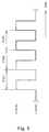
- An output shaft rotating speed detector 36 detects the rotation speed Nout of the output shaft 14-2 based on the time length of pulse intervals in a plurality of pulse signals output from the AD converter 34 (the electromagnetic pickup sensor 16). To detect the rotation speed Nout of the output shaft 14-2 based on, for example, the time lengths of pulse intervals ⁇ tp1, ⁇ tp2, and ⁇ tp3 in four pulse signals as shown in Fig. 5 , each time length of pulse interval ⁇ tp1, ⁇ tp2, and ⁇ tp3 is detected and temporarily stored in a memory 38 for output shaft rotating speed detection successively.
- the rotation speed Nout of the output shaft 14-2 is computed using the time lengths of pulse intervals ⁇ tp1, ⁇ tp2, and ⁇ tp3 stored in the memory 38 for output shaft rotating speed detection (by calculating an average value of the time lengths of pulse intervals ⁇ tp1, ⁇ tp2, and ⁇ tp3, for example).
- the determined rotation speed Nout of the output shaft 14-2 is stored in the memory 38 for output shaft rotating speed detection. It should be noted that the number of pulses used for determining the rotation speed Nout of the output shaft 14-2 is variable as described later. Further, in the detection of the time lengths of pulse interval ⁇ tp1, ⁇ tp2, and ⁇ tp3, the length of either a time interval between rising edges of pulses or a time interval between falling edges of pulses may be detected.
- a speed change controller 40 performs a clutch-to-clutch speed change control in which the transmission gear ratio of the automatic transmission 14 is changed by disengaging an engaged frictional engagement device while engaging a released frictional engagement device which has not been engaged.
- the speed change controller 40 controls engaging forces of the frictional engagement devices to be disengaged and to be engaged based on the rotation speed Nin of the input shaft 14-1 determined by the input shaft rotating speed detector 26 and the rotation speed Nout of the output shaft 14-2 determined by the output shaft rotating speed detector 36.
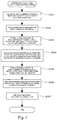
- FIG. 6 is a flowchart showing an example of a routine for calculating a motor rotating speed executed by the motor controller 20. This routine is repeated at intervals of predetermined control cycles.
- the input shaft rotating speed detector 26 reads out and obtains, from the memory 28 for input shaft rotating speed detection, the time length of pulse interval ⁇ t3 in the pulse signal from the RD converter 24 in step S101.
- the time length of pulse interval ⁇ t3 detected at a time closest to the time tn is obtained.
- the input shaft rotating speed detector 26 calculates the rotation speed Nin of the motor 10 (the rotation speed Nin of the input shaft 14-1) from the time length of pulse interval ⁇ t3 obtained in step S101.
- the rotation speed Nin of the motor 10 is calculated by the constant-angle detection.
- step S103 the input shaft rotating speed detector 26 judges whether or not the rotation speed Nin of the motor 10 calculated through the constant-angle detection in step S102 is greater than a predetermined rotation speed N1.
- the predetermined rotation speed N1 is specified as a threshold value at which accuracy of computing the rotation speed Nin of the motor 10 in the constant-angle detection can be ensured.
- step S103 when the rotation speed Nin of the motor 10 is greater than the predetermined rotation speed N1 (when YES is judged in step S103), the accuracy of computing the rotation speed Nin of the motor 10 using the constant-angle detection is determined to be securable, and operation moves to step S105.
- step S104 the input shaft rotating speed detector 26 calculates the rotation speed Nin of the motor 10 in the constant-time detection. More specifically, the input shaft rotating speed detector 26 reads out and obtains, from the memory 28 for input shaft rotating speed detection, the rate of time-varying changes ⁇ / ⁇ t2's of the rotation angle ⁇ of the motor 10 detected within a predetermined time period ⁇ t1 earlier than the time tn, and calculates the rotation speed Nin of the motor 10 from the obtained rate of time-varying changes ⁇ / ⁇ t2 of the rotation angle ⁇ . Then, operation of the present routine is finished. As described above, the input shaft rotating speed detector 26 selects, according to the calculated result of the rotation speed Nin of the motor 10 obtained in the constant-angle detection, which of the constant-time detection and the constant-angle detection is used for determining the rotation speed Nin of the motor 10.
- step S105 the input shaft rotating speed detector 26 performs synchronization with a routine for calculating an output shaft rotating speed, which will be described later. For example, when a time lag between calculation timings of the rotation speed Nin of the motor 10 and the rotation speed Nout of the output shaft 14-2 occurs due to delay of communication between the motor controller 20 and the automatic transmission controller 22 or the like, the calculation timings are synchronized with respect to a delayed one of the calculation timings.
- step S106 the input shaft rotating speed detector 26 performs low-pass filtering (smoothing) of the calculated rotation speed Nin of the motor 10. Noise components contained in the calculated rotation speed Nin of the motor 10 are suppressed through the low-pass filtering (smoothing). Then, operation of this routine is finished.
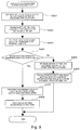
- Figs. 7 and 8 are flowcharts showing examples of a routine for calculating an output shaft rotating speed performed by the automatic transmission controller 22.
- the routine shown in Fig. 7 is executed when NO is judged in step S103, i.e. when the rotation speed Nin of the motor 10 is determined in the constant-time detection.
- the routine shown in Fig. 8 is executed when YES is judged in step S103, i.e. when the rotation speed Nin of the motor 10 is determined in the constant-angle detection.
- the output shaft rotating speed detector 36 calculates the number of pulse signals (an ideal number of pulses) np output from the AD converter 34 (the electromagnetic pickup sensor 16) within the predetermined time period ⁇ t1 which precedes the time tn.
- the ideal number of pulses (i.e. an average number of pulses) np may be estimated from the rotation speed Nout of the output shaft 14-2 which has been detected at a past point in time prior to the time tn, for example, estimated from the rotation speed Nout of the motor 10 detected in the previous detection (last detection).
- the ideal number of pulses np may be estimated from the rotation speed Nin of the motor 10 detected at a past point in time prior to the time tn, for example, that detected in the previous detection (last detection).
- the output shaft rotating speed detector 36 processes upper and lower limits of the ideal number of pulses np calculated in step S201. In this processing, the lower limit is restricted such that the ideal number of pulses np becomes 2 or greater, while the upper limit is restricted such that each time length of the pulse interval can be stored in the memory 38 for output shaft rotating speed detection.
- step S203 the output shaft rotating speed detector 36 reads out and obtains the time lengths of pulse intervals in the ideal np pulses from the memory 38 for output shaft rotating speed detection.
- step S204 the output shaft rotating speed detector 36 calculates the rotation speed Nout1 of the output shaft 14-2 using the time lengths of pulse intervals in the A pulse signals and calculates the rotation speed Nout2 of the output-shaft 14-2 using the time lengths of pulse intervals in the (A + 1) pulse signals.
- step S206 the output shaft rotating speed detector 36 performs synchronization with a routine for calculating a motor rotating speed. For example, when a time lag between calculation timings of the rotation speed Nin of the motor 10 and the rotation speed Nout of the output shaft 14-2 occurs due to delay of communication between the motor controller 20 and the automatic transmission controller 22 or the like, the calculation timings are synchronized with respect to a delayed one of the calculation timings.
- step S207 the output shaft rotating speed detector 36 performs low-pass filtering (smoothing) of the calculated rotation speed Nout of the output shaft 14-2. Noise components contained in the calculated rotation speed Nin of the motor 10 are suppressed through the low-pass filtering (smoothing). Then, operation of this routine is finished.
- the output shaft rotating speed detector 36 calculates the number of pulse signals (the ideal number of pulses) np output from the AD converter 34 (the electromagnetic pickup sensor 16) during the predetermined angle ⁇ 1 (for example, 180°) of rotation of the rotor for the motor 10 (the input shaft 14-1 of the automatic transmission 14) in step S301.
- the ideal number of pulses (the average number of pulses) np may be estimated using Equation 2 as follows.
- np Z / ⁇ ⁇ ⁇ 1 / 360
- Z is the total number of teeth on the tooth-shaped rotor
- ⁇ is the transmission gear ratio of the automatic transmission 14 which can be calculated from a ratio Nin/Nout of the rotation speed Nin of the motor 10 to the rotation speed Nout of the output shaft 14-2 detected at the past point in time prior to the time tn, for example, detected in the previous detection (last detection).
- Process steps from S302 to S307 in the routine for calculating an output shaft rotating speed of Fig. 8 are similar to those from S202 to S207 in the routine for calculating an output shaft rotating speed of Fig. 7 , and descriptions of the steps are not repeated.
- the rotation speed Nin of the motor 10 (the rotation speed Nin of the input shaft 14-1) is determined based on a change of the output signals from the resolver 12 in the predetermined time period ⁇ t1 (i.e. when the constant-time detection is performed)
- the number of pulse signals output from the electromagnetic pickup sensor 16 within the predetermined time period ⁇ t1 is calculated, and the rotation speed Nout of the output shaft 14-2 is obtained based on the time lengths of pulse intervals in the calculated number of pulse signals.
- the number of pulse signals from the electromagnetic pickup sensor 16 to be used for calculating the rotation speed Nout of the output shaft 14-2 may be changed, to synchronize (match) a detection period of the output signals from the resolver 12 to be used for calculating the rotation speed Nin of the motor 10 with a detection period of the pulse signals from the electromagnetic pickup sensor 16 to be used for calculating the rotation speed Nout of the output shaft 14-2.
- the response delays in the obtained rotation speed Nin of the motor 10 and rotation speed Nout of the output shaft 14-2 can be matched, which can provide consistent accuracy in detecting the rotation speed Nin of the motor 10 and the rotation speed Nout of the output shaft 14-2.
- the detection period of sensor signals used for calculating the rotation speed Nin of the input shaft 14-1 differs from the detection period of pulse signals used for calculating the rotation speed Nout of the output shaft 14-2, leading to an increased possibility of occurrence of a difference in detection accuracy between the rotation speeds of the input shaft 14-1 and the output shaft 14-2.
- the accuracy in detecting the rotation speed Nin of the input shaft 14-1 and that in detecting the rotation speed Nout of the output shaft 14-2 can be consistent even though time-varying changes of the rotation speeds Nin and Nout of the input and output shafts 14-1 and 14-2 are great.
- the time required for the predetermined angle ⁇ 1 of rotation of the rotor (the input shaft 14-1) in the motor 10 is determined based on the output signal from the resolver 12 to detect the rotation speed Nin of the motor 10 (i.e. when the constant-angle detection is performed)
- the number of pulse signals output from the electromagnetic pickup sensor 16 during the predetermined angle ⁇ 1 of rotation of the rotor in the motor 10 is calculated, and the rotation speed Nout of the output shaft 14-2 is determined based on the time lengths of pulse intervals in the calculated number of pulse signals.
- the number of pulse signals from the electromagnetic pickup sensor 16 to be used for calculating the rotation speed Nout of the output shaft 14-2 can be changed, to thereby synchronize (match) the detection period of the output signals from the resolver 12 used for calculating the rotation speed Nin of the motor 10 with the detection period of the pulse signals from the electromagnetic pickup sensor 16 used for calculating the rotation speed Nout of the output shaft 14-2. It is therefore possible to maintain consistent accuracy in detecting the rotation speed Nin of the motor 10 and detecting the rotation speed Nout of the output shaft 14-2.
- the constant-angle detection is performed to detect the rotation speed Nin of the motor 10, which can secure improved accuracy in detecting the rotation speed Nin of the motor 10 during high-speed rotation.
- the constant-time detection is performed to detect the rotation speed Nin of the motor 10, which can secure improved accuracy in detecting the rotation speed Nin of the motor 10 during low-speed rotation.
- detection accuracy of the rotation speed Nin of the motor 10 can be improved according to the present embodiment by selecting, based on the calculation result of the rotation speed Nin of the motor 10, either one of the constant-time detection and constant-angle detection performed for determining the rotation speed Nin of the motor 10.
- Fig. 9 is a flowchart showing another routine for calculating the motor rotating speed executed by the motor controller 20. This routine is repeatedly executed at intervals of predetermined control cycles.
- the input shaft rotating speed detector 26 calculates a rotation angle ⁇ of the rotor of the motor 10 (the input shaft 14-1 of the automatic transmission 14) while the predetermined np0 pulse signals are being output from the AD converter 34 (the electromagnetic pickup sensor 16).
- the rotation angle ⁇ of the rotor of the motor 10 may be estimated by Equation 3 described below.
- the transmission gear ratio ⁇ of the automatic transmission 14 can be calculated from the ratio Nin/Nout of the rotation speed Nin of the motor 10 and the rotation speed Nout of the output shaft 14-2 detected at a past point in time prior to the time tn, for example, the rotation speeds Nin, Nout detected in the previous detection (last detection).
- ⁇ np 0 ⁇ ⁇ ⁇ 360 / Z
- step S402 the input shaft rotating speed detector 26 obtains the length of time ⁇ t4 required for the rotor of the motor 10 to rotate by the angle ⁇ calculated in step S401.
- the length of required time ⁇ t4 may be detected from the output signals from the RD converter 24.
- step S403 the input shaft rotating speed detector 26 calculates the rotation speed Nin of the motor 10 from the length of required time ⁇ t4 obtained in step S402.
- step S404 the input shaft rotating speed detector 26 judges whether or not the rotation speed Nin of the motor 10 calculated in step S403 is greater than the predetermined rotation speed N1.
- the rotation speed Nin of the motor 10 is smaller than or equal to the predetermined rotation speed N1 (when NO is judged in step S404)
- the rotation speed Nin of the motor 10 is greater than the predetermined rotation speed N1 (when YES is judged in step S404)
- it is determined that the calculation accuracy of the rotation speed Nin of the motor 10 in step S403 can be secured, and operation moves to step S407.
- step S405 the input shaft rotating speed detector 26 calculates the length of time ⁇ t5 required for the output of the predetermined np0 pulse signals from the AD converter 34 (electromagnetic pickup sensor 16).
- the length of required time ⁇ t5 may be estimated from the rotation speed Nout of the output shaft 14-2 detected at a past point in time prior to the time tn, for example, that detected in the previous detection (last detection).
- the length of required time ⁇ t5 may be estimated from the rotation speed Nin of the motor 10 detected at a past point in time prior to the time tn, for example, that detected in the previous detection (last detection).
- step S406 the input shaft rotating speed detector 26 obtains the rate of time-varying change of the rotation angle ⁇ of the motor 10 within the calculated length of required time ⁇ t5, to.calculate the rotation speed Nin of the motor 10.
- the rate of change of the rotation angle ⁇ of the motor 10 with respect to time may be obtained from the output signals of the RD converter 24. Then, operation of this routine is finished.
- Process steps S407 and S408 in the routine for calculating the motor rotating speed of Fig. 9 are similar to process steps S105 and S106 in the routine for calculating the motor rotating speed of Fig. 6 , respectively, and description of the steps is not repeated.
- the length of time ⁇ t5 required for output of the predetermined np0 pulse signals from the electromagnetic pickup sensor 16 is calculated, and the rotation speed Nin of the motor 10 is calculated based on changes of the output signals from the resolver 12 within the calculated length of required time ⁇ t5.
- the detection period of the output signals from the resolver 12 used for calculating the rotation speed Nin of the motor 10 can be matched with that of the pulse signals from the electromagnetic pickup sensor 16 used for calculating the rotation speed Nout of the output shaft 14-2, consistent accuracy can be maintained between detections of the rotation speed Nin of the motor 10 and the rotation speed Nout of the output shaft 14-2.
- the angle ⁇ by which the rotor of the motor 10 rotates while the predetermined np0 pulse signals are being output from the electromagnetic pickup sensor 16 is calculated, and the length of time ⁇ t4 required for the rotor of the motor 10 to rotate by the calculated angle ⁇ is determined based on the output signals from the resolver 12 to detect the rotation speed Nin of the motor 10. Also with this configuration, the detection period of the output signals from the resolver 12 used for calculating the rotation speed Nin of the motor 10 can be matched with that of the pulse signals from the electromagnetic pickup sensor 16 used for calculating the rotation speed Nout of the output shaft 14-2, thereby making it possible to maintain consistent accuracy between detections of the rotation speed Nin of the motor 10 and the rotation speed Nout of the output shaft 14-2.
- the rotation speed Nin of the input shaft 14-1 is detected by the resolver 12 and the rotation speed Nout of the output shaft 14-2 is detected by the electromagnetic pickup sensor 16 in the automatic transmission 14, the rotation speed Nin of input shaft 14-1 may be detected by the electromagnetic pickup sensor, and the rotation speed Nout of output shaft 14-2 may be detected by the resolver depending on the overall configuration.of the system.
- the rotation speed Nout of the output shaft 14-2 may be determined using an output-shaft-side electromagnetic pickup sensor in which a pulse signal is output for each predetermined angle ⁇ 1 of rotation of the output shaft 14-2, while the rotation speed Nin of input shaft 14-1 may be determined using an input-shaft-side electromagnetic pickup sensor in which a pulse signal is output for each predetermined angle ⁇ 2 of rotation of the input shaft 14-1.
- the input shaft rotating speed detector 26 detects the rotation speed Nin of the input shaft 14-1 based on the time lengths of pulse interval in the predetermined np0 pulse signals output from the input-shaft-side electromagnetic pickup sensor.
- the output shaft rotating speed detector 36 detects the rotation speed Nout of the output shaft 14-2 based on the time lengths of pulse intervals in a plurality of pulse signals output from the output-shaft-side electromagnetic pickup sensor.
- the output shaft rotating speed detector 36 estimates the number of pulse signals (the ideal number of pulses) np which will be output from the electromagnetic pickup sensor on the output shaft side during the output of the predetermined np0 pulse signals from the electromagnetic pickup sensor on the input shaft side, and detects the rotation speed Nout of the output shaft 14-2 based on the time lengths of pulse intervals in the estimated ideal np pulses. Also with this configuration, because the detection period of the pulse signals used for calculating the rotation speed Nin of the input shaft 14-1 can be matched with that of the pulse signals used for calculating the rotation speed Nout of the output shaft 14-2, consistent accuracy can be maintained between detections of the rotation speed Nin of the input shaft 14-1 and the rotation speed Nout of the output shaft 14-2. It should be noted that the ideal number of pulses np may be calculated from the ratio Nin/Nout of the rotation speed Nin of the input shaft 14-1 to the rotation speed Nout of the output shaft 14-2 found in a previous detection (for example, the last detection).
- the output shaft rotating speed detector 36 is also capable of detecting the rotation speed Nout of the output shaft 14-2 based on the time lengths of pulse intervals in the predetermined np0 pulse signals output from the electromagnetic pickup sensor on the output shaft side.
- the input shaft rotating speed detector 26 estimates the number of pulse signals (the ideal number of pulses) np output from the electromagnetic pickup sensor on the input shaft side during the output of the predetermined np0 pulse signals from the electromagnetic pickup sensor on the output shaft side, and detects the rotation speed Nin of the input shaft 14-1 based on the time lengths of pulse intervals in the estimated ideal np pulses.
- FIG. 10 shows a schematic configuration of a driving system in a hybrid vehicle having the rotation speed detecting apparatus according to the present embodiment of this invention.
- the rotor of the motor 10 is connected to the input shaft 14-1 of the automatic transmission 14 which performs a speed change of drive power transferred from the motor 10 to the input shaft 14-1 and transfers the speed-changed drive power to the output shaft 14-2.
- the drive power transferred to the output shaft 14-2 of the automatic transmission 14 is further transferred via a differential gear 17 to drive wheels 19 for use in driving a load, such as a vehicle.
- An output shaft 50-1 of an engine 50 is coupled to a power transfer mechanism 52.
- the power transfer mechanism 52 is connected to the output shaft 14-2 of the automatic transmission 14 (the drive wheels 19) and a rotor of a generator 54 to distribute the drive power from the engine 50 among the drive wheels 19 and the generator 54.
- the power transfer mechanism 52 may be configured, for example, with a planetary gear mechanism having a ring gear, a carrier, and a sun gear. Operation conditions of the motor 10 and the generator 54 are controlled by the motor controller 20.
- the resolver 12 is provided to the motor 10. Further, to detect the rotation speed Nout of the drive wheels 19 (the rotation speed Nout of the output shaft 14-2 of the automatic transmission 14), the electromagnetic pickup sensor 16 is provided to the drive wheels 19.
- Other components are similar to those depicted in Figs. 1 and 2 , and description of the similar components is not repeated.
- the motor controller 20 and the automatic transmission controller 22 are configured as individual separate controllers, the two controllers may be integrally configured.
Landscapes
- Physics & Mathematics (AREA)
- General Physics & Mathematics (AREA)
- Engineering & Computer Science (AREA)
- General Engineering & Computer Science (AREA)
- Mechanical Engineering (AREA)
- Control Of Transmission Device (AREA)
Claims (8)
- Appareil de détection de vitesse de rotation (20, 22) destiné à détecter des vitesses de rotation (Nin, Nout) d'un premier élément rotatif (18, 14-2) et d'un deuxième élément rotatif (10, 14-1) en utilisant un premier capteur (16) qui délivre un signal d'impulsion pour chaque premier angle prédéterminé (δθ1) de rotation du premier élément rotatif (18, 14-2) et un deuxième capteur (12) qui délivre un signal correspondant à un angle de rotation (α) du deuxième élément rotatif (10, 14-1), comportant :un premier détecteur de vitesse de rotation (36) configuré pour détecter la vitesse de rotation (Nout) du premier élément rotatif (18, 14-2) sur la base d'une durée d'intervalles d'impulsion dans une pluralité de signaux d'impulsion délivrés par le premier capteur (16), etun deuxième détecteur de vitesse de rotation (26) configuré pour détecter la vitesse de rotation (Nin) du deuxième élément rotatif (10, 14-1) sur la base du signal de sortie du deuxième capteur (12), dans lequell'appareil de détection de vitesse de rotation est configuré pour synchroniser une période de détection du signal d'impulsion provenant du premier capteur (16) utilisé pour déterminer la vitesse de rotation (Nout) du premier élément rotatif (18, 14-2) avec une période de détection du signal de sortie provenant du deuxième capteur (12) utilisé pour déterminer la vitesse de rotation (Nin) du deuxième élément rotatif (10, 14-1) pour détecter les vitesses de rotation (Nin, Nout) des premier et deuxième éléments rotatifs, dans lequelledit deuxième détecteur de vitesse de rotation (26) est configuré pour réaliser de manière sélective une détection à temps constant dans laquelle la vitesse de rotation du deuxième élément rotatif (10, 14-1) est déterminée sur la base d'un changement du signal de sortie du deuxième capteur (12) dans une durée prédéterminée (δt1), et une détection à angle constant dans laquelle une durée (δt3) exigée pour un deuxième angle de rotation prédéterminé (δα1) du deuxième élément rotatif (10, 14-1) est déterminé sur la base du signal de sortie du deuxième capteur (12), pour détecter la vitesse de rotation du deuxième élément rotatif (10, 14-1), dans lequelquand le deuxième détecteur de vitesse de rotation (26) est configuré pour réaliser la détection à temps constant pour détecter la vitesse de rotation du deuxième élément rotatif (10, 14-1), le premier détecteur de vitesse de rotation (36) est configuré pour calculer le nombre (np) de signaux d'impulsion délivrés par le premier capteur (16) dans la durée prédéterminée (δt1), pour détecter la vitesse de rotation (Nout) du premier élément rotatif (18, 14-2) sur la base d'une durée des intervalles d'impulsion dans le nombre calculé (np) de signaux d'impulsion, etquand le deuxième détecteur de vitesse de rotation (26) est configuré pour réaliser la détection à angle constant pour détecter la vitesse de rotation du deuxième élément rotatif (10, 14-1), le premier détecteur de vitesse de rotation (36) est configuré pour calculer le nombre (np) de signaux d'impulsion délivrés par le premier capteur (16) pendant le deuxième angle de rotation prédéterminé (δα1) du deuxième élément rotatif (10, 14-1), pour détecter la vitesse de rotation du premier élément rotatif (18, 14-2) sur la base d'une durée des intervalles d'impulsion dans le nombre calculé de signaux d'impulsion,dans lequel le deuxième détecteur de vitesse de rotation (26) est configuré pour sélectionner, sur la base d'un résultat de détection à angle constant de la vitesse de rotation (Nin) du deuxième élément rotatif (10, 14-1), une de la détection à temps constant et de la détection à angle constant devant être utilisée pour détecter la vitesse de rotation du deuxième élément rotatif (10, 14-1), caractérisé en ce quele deuxième détecteur de vitesse de rotation (26) est configuré pour sélectionner l'utilisation de la détection à angle constant dans la détection de la vitesse de rotation du deuxième élément rotatif (10, 14-1) quand le résultat de détection à angle constant de la vitesse de rotation (Nin) du deuxième élément rotatif (10, 14-1) est supérieur à une vitesse de rotation prédéterminée (N1), et pour sélectionner l'utilisation de la détection à temps constant dans la détection de la vitesse de rotation (Nin) du deuxième élément rotatif (10, 14-1) quand le résultat de détection à angle constant de la vitesse de rotation du deuxième élément rotatif (10, 14-1) est inférieur ou égal à la vitesse de rotation prédéterminée (N1).
- Appareil de détection de vitesse de rotation (20, 22) selon la revendication 1, dans lequel
le premier détecteur de vitesse de rotation est configuré pour détecter la vitesse de rotation du premier élément rotatif (18, 14-2) sur la base des durées des intervalles d'impulsion dans n signaux d'impulsion et dans (n + 1) signaux d'impulsion où n est un nombre naturel supérieur ou égal à 2 quand le nombre calculé de signaux d'impulsion tombe entre n et n + 1. - Appareil de détection de vitesse de rotation (20, 22) destiné à détecter des vitesses de rotation (Nin, Nout) d'un premier élément rotatif (18, 14-2) et d'un deuxième élément rotatif (10, 14-1) en utilisant un premier capteur (16) qui délivre un signal d'impulsion pour chaque angle de rotation prédéterminé du premier élément rotatif (18, 14-2) et un deuxième capteur (12) qui délivre un signal correspondant à un angle de rotation du deuxième élément rotatif (10, 14-1), comportant :un premier détecteur de vitesse de rotation (36) configuré pour détecter la vitesse de rotation (Nout) du premier élément rotatif (18, 14-2) sur la base d'une durée d'intervalles d'impulsion dans un nombre prédéterminé (np0) de signaux d'impulsion délivrés par le premier capteur (16), etun deuxième détecteur de vitesse de rotation (26) configuré pour détecter la vitesse de rotation (Nin) du deuxième élément rotatif (10, 14-1) sur la base du signal de sortie du deuxième capteur (12), dans lequell'appareil de détection de vitesse de rotation est configuré pour synchroniser une période de détection du signal d'impulsion provenant du premier capteur (16) utilisé pour déterminer la vitesse de rotation (Nout) du premier élément rotatif (18, 14-2) avec une période de détection du signal de sortie provenant du deuxième capteur (12) utilisé pour déterminer la vitesse de rotation (Nin) du deuxième élément rotatif (10, 14-1), dans lequelledit deuxième détecteur de vitesse de rotation (26) est configuré pour sélectionner une détection à temps constant dans laquelle une durée (δt5) exigée pour la sortie du nombre prédéterminé (np0) de signaux d'impulsion du premier capteur (16) est calculée, pour détecter la vitesse de rotation du deuxième élément rotatif (10, 14-1) sur la base d'un changement du signal de sortie du deuxième capteur (12) dans la durée exigée calculée (δt5), ou pour sélectionner une détection à angle constant dans laquelle un angle de rotation (δα) du deuxième élément rotatif (10, 14-1) pendant la sortie du nombre prédéterminé (np0) de signaux d'impulsion du premier capteur est calculé et qui détermine une durée (δt4) exigée pour que le deuxième élément rotatif (10, 14-1) tourne de l'angle de rotation calculé (δα) sur la base du signal de sortie du deuxième capteur (12), pour détecter la vitesse de rotation du deuxième élément rotatif (10, 14-1), dans lequelle deuxième détecteur de vitesse de rotation (26) est configuré pour sélectionner, sur la base d'un résultat de détection à angle constant de la vitesse de rotation du deuxième élément rotatif (10, 14-1), une de la détection à temps constant et de la détection à angle constant devant être utilisée pour détecter la vitesse de rotation du deuxième élément rotatif (10, 14-1), caractérisé en ce quele deuxième capteur de vitesse de rotation est configuré pour sélectionner l'utilisation de la détection à angle constant dans la détection de la vitesse de rotation (Nin) du deuxième élément rotatif (10, 14-1) quand le résultat de détection à angle constant de la vitesse de rotation du deuxième élément rotatif (10, 14-1) est supérieur à une vitesse de rotation prédéterminée (N1), et pour sélectionner l'utilisation de la détection à temps constant dans la détection de la vitesse de rotation du deuxième élément rotatif (10, 14-1) quand le résultat de détection à angle constant de la vitesse de rotation du deuxième élément rotatif (10, 14-1) est inférieur ou égal à la vitesse de rotation prédéterminée (N1).
- Appareil de détection de vitesse de rotation (20, 22) selon la revendication 3, dans lequel
le deuxième détecteur de vitesse de rotation est configuré pour calculer la durée exigée sur la base d'une vitesse de rotation précédemment détectée du premier élément rotatif (18, 14-2). - Appareil de détection de vitesse de rotation (20, 22) selon la revendication 3, dans lequel
le deuxième détecteur de vitesse de rotation est configuré pour calculer l'angle de rotation du deuxième élément rotatif (10, 14-1) sur la base de vitesses de rotation précédemment détectées (Nin, Nout) des premier et deuxième éléments rotatifs (10, 14-1). - Appareil de détection de vitesse de rotation (20, 22) selon la revendication 1 ou 3 dans lequel
le premier capteur (16) est un capteur électromagnétique alors que le deuxième capteur (12) est un résolveur. - Appareil de détection de vitesse de rotation (20, 22) selon la revendication 3,
dans lequel le deuxième détecteur de vitesse de rotation est configuré pour détecter la vitesse de rotation du deuxième élément rotatif (10, 14-1) sur la base d'une durée d'intervalles d'impulsion dans une pluralité de signaux d'impulsion délivrés par le deuxième capteur (12), et dans lequel
le premier détecteur de vitesse de rotation est configuré pour calculer le nombre de signaux d'impulsion délivrés par le premier capteur (16) pendant une sortie du nombre prédéterminé de signaux d'impulsion du deuxième capteur (12), pour détecter la vitesse de rotation du premier élément rotatif (10, 14-1) sur la base d'une durée d'intervalles d'impulsion dans le nombre calculé de signaux d'impulsion. - Dispositif de commande de transmission automatique (22) destiné à réaliser, sur une transmission automatique capable de commuter un dispositif d'engagement à friction devant être engagé parmi une pluralité de dispositifs d'engagement à friction pour changer un rapport de transmission entre des arbres d'entrée et de sortie, une commande de changement de vitesse de désengagement d'un dispositif engagé des dispositifs d'engagement à friction tout en engageant un dispositif libéré des dispositifs d'engagement à friction qui n'a pas été engagé, le dispositif de commande de transmission automatique étant caractérisé en ce qu'il comporte :un appareil de détection de vitesse de rotation selon l'une quelconque des revendications 1 à 7, dans lequelune vitesse de rotation d'un des arbres d'entrée et de sortie est détectée comme la vitesse de rotation du premier élément rotatif (18, 14-2) alors qu'une vitesse de rotation de l'autre des arbres d'entrée et de sortie est détectée comme la vitesse de rotation du deuxième élément rotatif (10, 14-1), etla commande de changement de vitesse est réalisée sur la base des vitesses de rotation (Nin, Nout) des arbres d'entrée et de sortie détectées en utilisant l'appareil de détection de vitesse de rotation.
Applications Claiming Priority (2)
| Application Number | Priority Date | Filing Date | Title |
|---|---|---|---|
| JP2005164830A JP4725201B2 (ja) | 2005-06-03 | 2005-06-03 | 回転数検出装置及びそれを備えた自動変速機の制御装置 |
| PCT/JP2006/311136 WO2006129811A1 (fr) | 2005-06-03 | 2006-05-26 | Appareil de detection de vitesse de rotation et son controleur de transmission automatique |
Publications (2)
| Publication Number | Publication Date |
|---|---|
| EP1886148A1 EP1886148A1 (fr) | 2008-02-13 |
| EP1886148B1 true EP1886148B1 (fr) | 2016-06-22 |
Family
ID=36785212
Family Applications (1)
| Application Number | Title | Priority Date | Filing Date |
|---|---|---|---|
| EP06766435.9A Expired - Lifetime EP1886148B1 (fr) | 2005-06-03 | 2006-05-26 | Appareil de detection de vitesse de rotation et son controleur de transmission automatique |
Country Status (5)
| Country | Link |
|---|---|
| US (1) | US7626382B2 (fr) |
| EP (1) | EP1886148B1 (fr) |
| JP (1) | JP4725201B2 (fr) |
| CN (1) | CN101107530B (fr) |
| WO (1) | WO2006129811A1 (fr) |
Families Citing this family (21)
| Publication number | Priority date | Publication date | Assignee | Title |
|---|---|---|---|---|
| US8405384B1 (en) * | 2007-02-20 | 2013-03-26 | Zulia Technologies Inc. | Non-contact tachometer and sensor |
| DE102007032139A1 (de) | 2007-06-30 | 2009-01-02 | Robert Bosch Gmbh | Steuervorrichtung mit Positionssensor |
| US8027771B2 (en) * | 2007-09-13 | 2011-09-27 | GM Global Technology Operations LLC | Method and apparatus to monitor an output speed sensor during operation of an electro-mechanical transmission |
| JP5182571B2 (ja) * | 2008-06-26 | 2013-04-17 | アイシン精機株式会社 | センサ信号処理装置 |
| US8185359B2 (en) | 2008-07-03 | 2012-05-22 | Caterpillar Inc. | System and method for transforming data between the time domain and the combustion pulse domain |
| US8333450B2 (en) * | 2008-12-16 | 2012-12-18 | Fuji Xerox Co., Ltd. | Speed calculation device, speed estimation device, image forming device, and storage medium |
| US8143822B2 (en) * | 2008-12-19 | 2012-03-27 | Tai-Her Yang | Bidirectional unequal speed electric motor driven bidirectional output system |
| US20100156210A1 (en) * | 2008-12-19 | 2010-06-24 | Tai-Her Yang | Bidirectional unequal speed electric motor driven constant directional output system |
| US8143823B2 (en) * | 2008-12-19 | 2012-03-27 | Tai-Her Yang | Bidirectional different speed ratio electric motor driving device with bidirectional input |
| CN101789755B (zh) * | 2008-12-19 | 2015-05-20 | 杨泰和 | 双向不等速电马达恒向输出驱动系统 |
| JP5005054B2 (ja) * | 2010-02-23 | 2012-08-22 | 本田技研工業株式会社 | 発進クラッチ制御装置 |
| US8437884B2 (en) * | 2010-07-28 | 2013-05-07 | GM Global Technology Operations LLC | System and method for detecting vehicle motion |
| CN102590542A (zh) * | 2011-01-07 | 2012-07-18 | 江西华电电力有限责任公司 | 螺杆膨胀动力机的测速装置及测速方法 |
| CN102680727B (zh) * | 2012-05-24 | 2014-07-30 | 柳州职业技术学院 | 实时两轴转角差检测仪 |
| CN104019049B (zh) * | 2013-03-01 | 2016-08-10 | 鸿富锦精密电子(天津)有限公司 | 风扇转速测试装置 |
| CN104730277B (zh) * | 2015-04-01 | 2017-10-03 | 武汉理工通宇新源动力有限公司 | 一种变速箱转速测量方法 |
| US10351729B2 (en) * | 2016-03-03 | 2019-07-16 | Motorola Mobility Llc | Polysiloxane films and methods of making polysiloxane films |
| DE102017221876A1 (de) * | 2017-12-05 | 2019-06-06 | Zf Friedrichshafen Ag | Gradientenbestimmung |
| CN110045139B (zh) * | 2019-03-26 | 2021-02-09 | 天津鼎成高新技术产业有限公司 | 一种基于脉冲时间的转速测量系统 |
| CN114719015B (zh) * | 2022-03-07 | 2023-12-15 | 潍柴动力股份有限公司 | 变速箱输出轴周期采集时间获取方法及盲区转速估算方法 |
| CN115071726B (zh) * | 2022-06-13 | 2026-01-23 | 经纬恒润(天津)研究开发有限公司 | 一种轮速测量方法、装置和设备 |
Citations (2)
| Publication number | Priority date | Publication date | Assignee | Title |
|---|---|---|---|---|
| WO1998005544A1 (fr) * | 1996-08-07 | 1998-02-12 | Trw Lucas Varity Electric Steering Ltd. | Perfectionnements relatifs aux boites de vitesse |
| JPH10184874A (ja) * | 1996-12-24 | 1998-07-14 | Toyota Motor Corp | 変速機の回転数検出装置 |
Family Cites Families (11)
| Publication number | Priority date | Publication date | Assignee | Title |
|---|---|---|---|---|
| US3922910A (en) | 1971-12-07 | 1975-12-02 | Ferranti Ltd | Means for determining the relative speeds of the input and output shafts of a gearbox |
| US4258324A (en) * | 1977-08-29 | 1981-03-24 | The Bendix Corporation | Signal conditioning circuit for magnetic sensing means |
| JPS60161520A (ja) * | 1984-01-31 | 1985-08-23 | Nippon Denso Co Ltd | 回転角検出装置 |
| JPS63220788A (ja) | 1987-03-06 | 1988-09-14 | Daikin Ind Ltd | 空気調和機の送風機制御装置 |
| US5425284A (en) * | 1993-09-07 | 1995-06-20 | Eaton Corporation | Automated mechanical transmission control system/method |
| JPH07306218A (ja) | 1994-05-16 | 1995-11-21 | Mazda Motor Corp | 車輪速度検出装置および車輪のスリップ制御装置 |
| CN1091416C (zh) * | 1997-01-29 | 2002-09-25 | 倪高松 | 汽车自动变速方法及装置 |
| JP2002112580A (ja) | 2000-09-29 | 2002-04-12 | Nissan Motor Co Ltd | 回転体の位相検出装置 |
| US6411080B1 (en) * | 2001-04-02 | 2002-06-25 | Delphi Technologies, Inc. | Signal processing method for a variable reluctance vehicle speed sensing mechanism |
| JP2004077136A (ja) | 2002-08-09 | 2004-03-11 | Toyota Motor Corp | モータの回転角検出装置及び検出方法 |
| JP4214799B2 (ja) * | 2003-02-27 | 2009-01-28 | アイシン精機株式会社 | 回転検出装置 |
-
2005
- 2005-06-03 JP JP2005164830A patent/JP4725201B2/ja not_active Expired - Fee Related
-
2006
- 2006-05-26 WO PCT/JP2006/311136 patent/WO2006129811A1/fr not_active Ceased
- 2006-05-26 CN CN2006800031268A patent/CN101107530B/zh not_active Expired - Lifetime
- 2006-05-26 EP EP06766435.9A patent/EP1886148B1/fr not_active Expired - Lifetime
- 2006-05-26 US US11/791,123 patent/US7626382B2/en active Active
Patent Citations (2)
| Publication number | Priority date | Publication date | Assignee | Title |
|---|---|---|---|---|
| WO1998005544A1 (fr) * | 1996-08-07 | 1998-02-12 | Trw Lucas Varity Electric Steering Ltd. | Perfectionnements relatifs aux boites de vitesse |
| JPH10184874A (ja) * | 1996-12-24 | 1998-07-14 | Toyota Motor Corp | 変速機の回転数検出装置 |
Also Published As
| Publication number | Publication date |
|---|---|
| JP2006337287A (ja) | 2006-12-14 |
| JP4725201B2 (ja) | 2011-07-13 |
| EP1886148A1 (fr) | 2008-02-13 |
| CN101107530A (zh) | 2008-01-16 |
| US20080012551A1 (en) | 2008-01-17 |
| WO2006129811A1 (fr) | 2006-12-07 |
| CN101107530B (zh) | 2011-08-31 |
| US7626382B2 (en) | 2009-12-01 |
Similar Documents
| Publication | Publication Date | Title |
|---|---|---|
| US7626382B2 (en) | Rotation speed detecting apparatus and automatic transmission controller having the apparatus | |
| JP5005586B2 (ja) | エンジン回転数表示装置 | |
| EP1195542B1 (fr) | Transmission hydro-mécanique | |
| EP1363801B1 (fr) | Controleur de transmission de vehicule | |
| US9440636B2 (en) | Vibration damping control apparatus | |
| CN104048037B (zh) | 车辆动力传动系统和用于控制车辆的方法 | |
| US5107430A (en) | Method and a system for controlling traction in motor vehicles with mechanical gearboxes | |
| US6411080B1 (en) | Signal processing method for a variable reluctance vehicle speed sensing mechanism | |
| US7360458B2 (en) | Method and device for determining the torque on gear shafts | |
| EP1621789B1 (fr) | Dispositif de commande d'un embrayage de démarrage | |
| JPH0469448A (ja) | 変速機の入力回転速度検出装置 | |
| JP2010520980A (ja) | マニュアルトランスミッションの出力回転数を求める方法 | |
| JP3484043B2 (ja) | 加速度計算装置 | |
| JPS603555A (ja) | パルス性信号の入力処理方式 | |
| KR100196802B1 (ko) | 자동 변속 차량의 토크 측정장치와 이를 이용한 토크 측정방법 | |
| JPH0520621B2 (fr) | ||
| CN111033091B (zh) | 车辆的控制装置及车辆的控制方法 | |
| JP3637546B2 (ja) | 無段変速機 | |
| GB2330888A (en) | Clutch control method wherein two signals are synchronized | |
| SU1377343A2 (ru) | Устройство дл регулировани рабочего режима землеройно-транспортной машины | |
| EP2017505B1 (fr) | Système de suggestion d'un changement de vitesses pour un véhicule à moteur fourni avec un moteur et boîte de vitesses avec des rapports discrets | |
| KR20050060911A (ko) | 자동 변속 차량의 n→r 변속 제어방법 | |
| KR20030077338A (ko) | 차량의 차속 검출방법 | |
| JPH0415364A (ja) | 作業車の車速制御装置 | |
| JPH0314961A (ja) | 変速機におけるトルク検出装置 |
Legal Events
| Date | Code | Title | Description |
|---|---|---|---|
| PUAI | Public reference made under article 153(3) epc to a published international application that has entered the european phase |
Free format text: ORIGINAL CODE: 0009012 |
|
| 17P | Request for examination filed |
Effective date: 20070531 |
|
| AK | Designated contracting states |
Kind code of ref document: A1 Designated state(s): DE FR GB |
|
| 17Q | First examination report despatched |
Effective date: 20080312 |
|
| RBV | Designated contracting states (corrected) |
Designated state(s): DE FR GB |
|
| DAX | Request for extension of the european patent (deleted) | ||
| R17C | First examination report despatched (corrected) |
Effective date: 20080312 |
|
| RAP1 | Party data changed (applicant data changed or rights of an application transferred) |
Owner name: TOYOTA JIDOSHA KABUSHIKI KAISHA |
|
| REG | Reference to a national code |
Ref country code: DE Ref legal event code: R079 Ref document number: 602006049394 Country of ref document: DE Free format text: PREVIOUS MAIN CLASS: G01P0003440000 Ipc: G01P0003560000 |
|
| GRAP | Despatch of communication of intention to grant a patent |
Free format text: ORIGINAL CODE: EPIDOSNIGR1 |
|
| RIC1 | Information provided on ipc code assigned before grant |
Ipc: G01P 3/56 20060101AFI20151130BHEP Ipc: G01P 3/48 20060101ALI20151130BHEP Ipc: G01P 3/44 20060101ALI20151130BHEP Ipc: F16H 59/36 20060101ALI20151130BHEP |
|
| INTG | Intention to grant announced |
Effective date: 20151222 |
|
| GRAS | Grant fee paid |
Free format text: ORIGINAL CODE: EPIDOSNIGR3 |
|
| GRAA | (expected) grant |
Free format text: ORIGINAL CODE: 0009210 |
|
| RIN1 | Information on inventor provided before grant (corrected) |
Inventor name: ENDO, HIROATSU, Inventor name: KAKUSE, KENTARO, |
|
| AK | Designated contracting states |
Kind code of ref document: B1 Designated state(s): DE FR GB |
|
| REG | Reference to a national code |
Ref country code: GB Ref legal event code: FG4D |
|
| REG | Reference to a national code |
Ref country code: DE Ref legal event code: R096 Ref document number: 602006049394 Country of ref document: DE |
|
| REG | Reference to a national code |
Ref country code: DE Ref legal event code: R084 Ref document number: 602006049394 Country of ref document: DE |
|
| REG | Reference to a national code |
Ref country code: DE Ref legal event code: R097 Ref document number: 602006049394 Country of ref document: DE |
|
| PLBE | No opposition filed within time limit |
Free format text: ORIGINAL CODE: 0009261 |
|
| STAA | Information on the status of an ep patent application or granted ep patent |
Free format text: STATUS: NO OPPOSITION FILED WITHIN TIME LIMIT |
|
| 26N | No opposition filed |
Effective date: 20170323 |
|
| GBPC | Gb: european patent ceased through non-payment of renewal fee |
Effective date: 20170526 |
|
| REG | Reference to a national code |
Ref country code: FR Ref legal event code: ST Effective date: 20180131 |
|
| PG25 | Lapsed in a contracting state [announced via postgrant information from national office to epo] |
Ref country code: GB Free format text: LAPSE BECAUSE OF NON-PAYMENT OF DUE FEES Effective date: 20170526 |
|
| PG25 | Lapsed in a contracting state [announced via postgrant information from national office to epo] |
Ref country code: FR Free format text: LAPSE BECAUSE OF NON-PAYMENT OF DUE FEES Effective date: 20170531 |
|
| P01 | Opt-out of the competence of the unified patent court (upc) registered |
Effective date: 20230427 |
|
| PGFP | Annual fee paid to national office [announced via postgrant information from national office to epo] |
Ref country code: DE Payment date: 20250402 Year of fee payment: 20 |
|
| REG | Reference to a national code |
Ref country code: DE Ref legal event code: R071 Ref document number: 602006049394 Country of ref document: DE |