EP1886151B1 - Dispositif de detection et de traitement d'une pluralite de valeurs de mesure d'une installation hgu - Google Patents
Dispositif de detection et de traitement d'une pluralite de valeurs de mesure d'une installation hgu Download PDFInfo
- Publication number
- EP1886151B1 EP1886151B1 EP05753537.9A EP05753537A EP1886151B1 EP 1886151 B1 EP1886151 B1 EP 1886151B1 EP 05753537 A EP05753537 A EP 05753537A EP 1886151 B1 EP1886151 B1 EP 1886151B1
- Authority
- EP
- European Patent Office
- Prior art keywords
- preprocessing
- loop control
- unit
- optical
- measured values
- Prior art date
- Legal status (The legal status is an assumption and is not a legal conclusion. Google has not performed a legal analysis and makes no representation as to the accuracy of the status listed.)
- Expired - Lifetime
Links
Images

Classifications
-
- G—PHYSICS
- G01—MEASURING; TESTING
- G01R—MEASURING ELECTRIC VARIABLES; MEASURING MAGNETIC VARIABLES
- G01R19/00—Arrangements for measuring currents or voltages or for indicating presence or sign thereof
- G01R19/25—Arrangements for measuring currents or voltages or for indicating presence or sign thereof using digital measurement techniques
- G01R19/2513—Arrangements for monitoring electric power systems, e.g. power lines or loads; Logging
-
- G—PHYSICS
- G01—MEASURING; TESTING
- G01R—MEASURING ELECTRIC VARIABLES; MEASURING MAGNETIC VARIABLES
- G01R25/00—Arrangements for measuring phase angle between a voltage and a current or between voltages or currents
- G01R25/02—Arrangements for measuring phase angle between a voltage and a current or between voltages or currents in circuits having distributed constants
Definitions
- the invention relates to a device for detecting and processing a plurality of measured values in an HVDC system with measuring units for detecting measured variables of the HVDC system with the acquisition of measured values and with preprocessing units.
- a DC voltage is generated in a first converter station from a polyphase AC voltage.
- the first converter station is connected on the DC voltage side to a second converter station, which converts the DC voltage back into a multi-phase AC voltage.
- the safe operation of such an HVDC system requires monitoring of the current flow and voltage on both the AC side and the DC side.
- a large number of measuring units therefore provide measured values of said currents and voltages to a control, regulation and monitoring system.
- the control, regulation and monitoring system the entire system is monitored on the one hand, so that in case of failure, a fast and safe shutdown of the HVDC system can take place.
- the control, regulation and monitoring system for the control of the converter stations is set up.
- the inverter stations include a plurality of power electronic switching elements, such as thyristors.
- the thyristors must be fired very precisely depending on the phase position of the AC voltage.
- the mains frequency therefore becomes the multiphase AC signal provided by the measuring units determined and calculated in a phase locked loop, the ignition timing of the thyristors in dependence of the mains frequency. Since a plurality of control units are required for the plurality of thyristors, the hardware complexity of such a control system is very high.
- each control unit must include inputs for a multiphase AC signal and the signal processing logic of that AC signal.
- the individual measuring units are to be connected directly to the respective control units. This leads to a very high cabling effort, whereby a high sensitivity to electromagnetic interference is given by the use of conventional transmission lines.
- Object of the present invention is to provide a device of the type mentioned in such a way that with reduced hardware and cabling the transmission reliability and thus the availability of the entire system is improved.
- the preprocessing units each have at least one optical input and at least two optical outputs, connected in series by means of optical waveguides and are each connected to at least one measuring unit and the means a last preprocessing unit, which is connected downstream of the remaining preprocessing units, is connected by means of optical waveguides to a control, regulation and monitoring system, wherein each preprocessing unit is adapted to receive and preprocess the measured values with means for obtaining optical data from the preprocessed measured values and both for the transmission of the generated by it as well as that of upstream preprocessing received optical data via the optical waveguide to a downstream preprocessing unit or to the control, regulation and monitoring system is set up, so that the last preprocessing unit is designed to provide all measured values for the control, regulation and monitoring system.
- the cabling effort of the entire system is significantly reduced, since the individual measuring units only have to be connected to preprocessing units assigned to them, and the individual preprocessing units transmit their data via an optical bus system to the control, regulation and monitoring system. This achieves a reduction in sensitivity to electromagnetic interference.
- the hardware complexity in the control, regulation and monitoring system is significantly reduced by designing the preprocessing unit for detecting and preprocessing the measured values assigned to it.
- each preprocessing unit has means for frequency and phase measurement with preprocessing of measured values of a multiphase AC voltage signal.
- the measurement of frequency and phase is carried out by one of the preprocessing units, so that all measured values can be transmitted to the control, regulation and monitoring system in phase synchronization as a function of the phase position of the alternating voltage.
- a phase tracking for each subunit of the control, regulation and monitoring system is omitted in the context of this invention.
- Each pre-processing unit can be configured as a master unit or as a slave unit. This is advantageous as a configurable preprocessing unit is independent of their later function produced, whereby the manufacturing cost can be reduced.
- each preprocessing unit has a plurality of analog and digital inputs for detecting the measured values assigned to it.
- the formation of an optical data bus for transmitting the measured values is possible, and on the other hand the measured values can be transmitted to independently operating control, regulation and monitoring systems by means of optical waveguides.
- optical waveguides ensures a cost-effective and secure transmission of the preprocessed measured values, which in particular is insensitive to electromagnetic interference.
- a first preprocessing unit which is not preceded by a preprocessing unit, is configured as a master unit, and the preprocessing units connected downstream of the first preprocessing unit are configured as slave units.
- the master unit for example, performs the measurement of frequency and phase of the polyphase AC voltage signal.
- the master unit is designed to generate a synchronization signal for the slave units and the control, regulation and monitoring system.
- the master unit from the measured frequency of the multi-phase AC voltage signal by means of a Frequency multiplication generate a system clock, which is used for the slave units as a clock for the preprocessing of their assigned measured values and simultaneously enables a synchronized transmission of the preprocessed measured values.
- the master unit is designed to generate an input signal for a phase locked loop arranged in the control, regulation and monitoring system.
- each preprocessing unit includes, in addition to the plurality of inputs for the measurements, configuration means for selecting a function as a master unit or slave unit, means for preprocessing the measurements, and electro-optical converters for converting the preprocessed measurements into optical data and transmitting and receiving means wherein the means for preprocessing comprise an input circuit for acquiring and converting analog measurements into digital values, as well as a programmable gate array and a digital signal processing unit.
- the device is suitable for flexible use, as by the use of electronic components such as a programmable gate array and a digital signal processing unit, such as a digital signal processor, a versatile use, for example as a master or slave unit, by simple Changing the programming of the programmable gate array or the digital signal processing unit is possible.
- the input circuitry includes operational amplifiers, low pass filters, analog / digital converters, and sampling means.
- operational amplifiers low pass filters
- analog / digital converters analog / digital converters
- sampling means sampling means
- the digital signal processing unit is designed to determine the frequency of the multiphase AC voltage signal. This is particularly advantageous because with a digital signal processing unit, such as a digital signal processor, such determination from digital values is easy to implement, and the frequency can be used to generate the master synchronization signal.
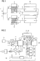
- FIG. 1 shows an embodiment of the device according to the invention as part of a high voltage direct current transmission system (HVDC system).
- the device has a plurality of measuring units 2a to 2n for current and voltage measurement both on the AC voltage as well as on the DC side of the HVDC system, of which in Fig. 1 only a redundantly designed current transformer is illustrated, the secondary currents are proportional to the alternating current through the AC busbar 1 flow.
- Preprocessing units 3a to 3i are connected to the measuring units 2a to 2n via lines. It goes without saying that a preprocessing unit can also be connected to a plurality of measuring units.
- the preprocessing units 3a to 3i have an input interface 4 for connection to the respective measuring units, as well as optical inputs 5 and outputs 6 and 7.
- the optical output 6 of a preprocessing unit is connected to the optical input 5 of a respective next preprocessing unit via an optical waveguide 8.
- the last preprocessing unit 3i is connected at its optical output 6 via an optical waveguide 9 to the control, regulation and monitoring system 10.
- the second optical output 7 of the preprocessing unit 3i can be connected to a second independent control, regulation and monitoring system 11 via a further optical waveguide 12.
- the same measured value sets are output at the two optical outputs 6 and 7 of the last preprocessing unit 3i.
- the connection of the optical output 7 with a second control, regulation and monitoring system 11 provides for this the same measured value set as for the control, regulation and monitoring system 10.
- the measuring units 2a to 2n are connected to a second arrangement of preprocessing units 3a 'to 3i'.
- the serially connected preprocessing units 3a to 3i and the likewise serially connected preprocessing units 3a 'to 3i' thus provide two independent measuring systems 3 and 3 '.
- the optical output 6 of the preprocessing unit 3i of the first measuring system 3 is connected to the optical input of the control, regulation and monitoring system 10, the optical output 7 of the preprocessing unit 3i with a second control, regulation and monitoring system 11.
- the optical output 6 'of the preprocessing unit 3i' of the second measuring system 3 ' is connected to the optical input of the control, regulation and monitoring system 11.
- the optical output 7 'of the preprocessing unit 3' is connected to a second optical input of the control, regulation and monitoring system 10.
- a preprocessing unit according to the invention leads to a significantly reduced wiring complexity and thus to a significantly reduced sensitivity to electromagnetic interference, since in this arrangement the preprocessing units are connected via an optical data bus to the control, regulation and monitoring systems.
- each of the measuring units 2a to 2n would have to be connected to the respective control, regulation and monitoring systems 10 and 11, which in addition to the increased cabling effort would also enormously increase the hardware complexity for the control, regulation and monitoring systems because the control, regulation and monitoring systems are a multiple of inputs would need for the individual measuring unit signals.
- the control, regulation and monitoring systems 10 and 11 are connected via a line arrangement, not shown, with controllable components of the HVDC system.
- the preprocessing unit 14 comprises a configuration means 15 with which the function of the preprocessing unit as master unit or slave unit can be set, as well as an input interface 4 with analog inputs and an input circuit with an operational amplifier 16, a low-pass filter 17, sampling means 18 and an analog / digital converter 19 ,
- a programmable gate array 20 connected to the input circuitry is connected via data lines 21 to a digital signal processing unit 22, such as a digital signal processor 22, as well as further lines 23 to optoelectronic transducers 25 and electro-optical transducers 26 for transmitting and receiving optical data.
- the preprocessing unit 14 further comprises a number of diagnostic means 27 to 30 with communication lines 31, 32. Via the communication lines 31, 32 of the diagnostic means may be a new programming of the programmable gate array 20 or the digital signal processing unit 22 or in case of failure, a troubleshooting or Error diagnosis.
- the input circuit with operational amplifier 16, sampling means 18, low-pass filter 17 and analog / digital converter 19 serves to convert the data received in analog form into digital measured values, which are processed in the programmable gate array 20 and in the digital signal processor 22. Via the programmable gate array 20, the digital measured values are displayed the digital signal processor 22 forwarded, in which an evaluation and preprocessing takes place.
- the digital signal processor 22 determines from the measured values the frequency of the measured alternating voltage as well as current and voltage values and returns them via the data lines 21 to the programmable gate array 20.
- the programmable gate array 20 can receive and buffer data from other preprocessing units via the optical bus connection 24 and an optoelectronic converter 26.
- the measured values obtained by the digital signal processor 22 are combined together with the measured values received from other preprocessing units to form a measured value set and transmitted via an electro-optical converter 25 to the optical bus connection 24 for further data transmission to a next preprocessing unit or the control, regulation and Surveillance system sent.
- FIG. 3 shows a schematic representation of the preprocessing of the measured values by the preprocessing units 3a ... 3i and the data transmission to the control, regulation and monitoring system.
- the measured values transmitted by the measuring units are converted into workable voltages by transducers, not shown, and fed to an antialiasing filter 33, which is connected to an A / D converter 34 for sampling and digitizing the measured values.
- the data are processed by means of low-pass filter 35 for suppressing interfering high-frequency components.
- the digital data is preprocessed by calculating the phase position 38 of the signals as well as further values such as amplitudes and magnitudes of the signals by a transformation 36 of the three-phase signal into a two-phase signal and further filtering 37.
- the data preprocessed in this way are available as measured values 39 for transmission to the control, regulation and supervisory system.
- the first preprocessing unit 3a is configured as a master unit, the further preprocessing units 3b to 3i as slave units.
- additional processing steps are performed in the digital signal processing unit 22.
- a frequency measurement 40 of the alternating voltage signal takes place in the master unit 3a, followed by frequency multiplication by a frequency multiplier 41.
- the measured frequency of the AC signal is multiplied by a factor of 128. This multiplied frequency serves as a clock frequency for the digital signal processing in the individual slave units 3b ... 3i and for data transmission to the control, regulation and monitoring system and the local processing there.
- the multiplication by a factor of 128 thus allows a sampling of the AC signal with 128 values per period of the AC signal.
- the master unit 3a generates a master synchronization signal 42 on the basis of the multiplied frequency calculated system clock, which is transmitted to the other slave units 3b to 3i, so that they are clocked by the master synchronization signal 42.
- the digital signal processing takes place as described above in the individual slave units 3b ... 3i.
- the master synchronization signal 42 serves to synchronize the data transmission of the individual preprocessing units 3a... 3i via the optical data bus 43 to the control, regulation and monitoring system 10.
- the optical measurement data 39 is converted into digital electronic signals.
- the control for the power electronic switching elements is calculated in a phase locked loop 45.
- the deviation between the measured phase of the alternating voltage signal and the phase of a controllable oscillator is determined in the phase locked loop 45 and the oscillator is adjusted according to the deviation, so that at the output 46 of the phase locked loop 45 is applied to the measured frequency signal with which a precise Control of the power electronic switching elements of the HVDC system can be done.
- further processing, control and regulating elements which are designated here schematically by reference numbers 47, 48, 49, are arranged in the control, regulation and monitoring system.
Landscapes
- Engineering & Computer Science (AREA)
- Power Engineering (AREA)
- Physics & Mathematics (AREA)
- General Physics & Mathematics (AREA)
- Arrangements For Transmission Of Measured Signals (AREA)
- Remote Monitoring And Control Of Power-Distribution Networks (AREA)
- Optical Communication System (AREA)
Claims (7)
- Dispositif de détection et de traitement d'une pluralité de valeurs de mesure dans une installation de courant continu à haute tension, ayant des unités (2a...2n) de mesure pour détecter des grandeurs de mesure de l'installation de courant continu à haute tension, en obtenant des valeurs de mesure et des unités de traitement préalable, dans lequel chaque unité (3a...3i) de traitement préalable à des moyens (20, 22) de mesure de la fréquence et de la phase d'un signal de tension alternative polyphasée, la mesure de la fréquence et de la phase étant effectuée par l'une des unités (3a...3i) de traitement préalable, de manière à ce que l'ensemble des valeurs de mesure puisse être transmis, en fonction de la position en phase de la tension alternative, donc en synchronisme de phase, au système (10, 11) de commande de réglage et de contrôle, chaque unité (3a...3i) de traitement préalable pouvant être configurée en unité (3a) maître ou en unité (3b...3i) esclave, les unités (3a...3i) de traitement préalable ayant chacune une pluralité d'entrées analogiques (4) et numériques pour détecter et traiter au préalable les valeurs de mesure qui leur sont associées, avec au moins une entrée (5) optique, et au moins deux sorties (6, 7) optiques de transmission des valeurs de mesure sont reliées entre elles en série au moyen de guides (8, 9) d'ondes lumineuses et sont reliées respectivement à au moins une unité (2a...2n) de mesure et qui, au moyen d'une dernière unité (31) de traitement préalable, qui est montée en aval du reste des unités de traitement préalable, est reliée au moyen de guides (8, 9) d'ondes lumineuses à un système (10, 11) de commande, de réglage et de contrôle, chaque unité (3a...3i) de traitement préalable étant conçue pour la réception et le traitement préalable des valeurs de mesure, en obtenant des valeurs de mesure optique, et tant pour la transmission des valeurs de mesure optique qu'elle produit qu'également elle reçoit des unités de traitement préalable en amont, par l'intermédiaire des guides d'ondes lumineuses à une unité de traitement préalable en aval ou au système (10, 11) de commande, de réglage et de contrôle, de manière à ce que la dernière unité de traitement préalable soit constituée pour la mise à disposition de l'ensemble des valeurs de mesure pour le système (10, 11) de commande, de réglage et de contrôle, la dernière unité (3i) de traitement préalable étant, sur sa sortie (6) optique par l'intermédiaire d'un guide (9) d'ondes lumineuses, reliée au système (10) de commande, de réglage et de contrôle et la deuxième sortie (7) optique de l'unité (3i) de traitement préalable pouvant être reliée à un deuxième système (11) indépendant de commande, de réglage et de contrôle par l'intermédiaire d'un autre guide (12) d'ondes lumineuses.
- Dispositif suivant la revendication 1,
caractérisé en ce que
une première unité (3a) de traitement préalable, en amont de laquelle une unité de traitement préalable n'est pas montée, est configurée en unité maître et les unités (3a...3i) de traitement préalable montées en aval de la première unité de traitement préalable sont configurées en unités esclaves. - Dispositif suivant la revendication 2,
caractérisé en ce que
l'unité (3a) maître est configurée pour produire un signal de synchronisation des unités (3b...3i) esclaves et du système (10) de commande, de réglage et de contrôle. - Dispositif suivant la revendication 3,
caractérisé en ce que
l'unité (3a) maître est constituée pour produire un signal d'entrée pour un circuit (45) de réglage de phase monté dans le système (10) de commande, de réglage et de contrôle. - Dispositif suivant l'une des revendications précédentes,
caractérisé en ce que
chaque unité (3a...3i) de traitement préalable a des moyens (15) de configuration pour choisir une fonction comme unité maître ou unité esclave, des moyens (16, 17, 18, 19, 20, 21 22) de traitement préalable des valeurs de mesure et un transducteur (25) électro-optique pour transformer les valeurs de mesure traitées au préalable en des données optiques et des moyens d'émission et de réception, les moyens de traitement préalable (16, 17, 18, 19, 20, 21, 22) comprenant un circuit (16, 17, 18, 19) d'entrée pour détecter et transformer des valeurs de mesure analogiques en des valeurs numériques, ainsi qu'un circuit (20) prédiffusé programmable et une unité (22) de traitement du signal numérique. - Dispositif suivant la revendication 5, caractérisé en ce que le circuit d'entrée comprend des amplificateurs (16) opérationnels, des filtres passe-bas, des moyens (18) d'échantillonnage et un convertisseur (19) analogique/ numérique.
- Dispositif suivant l'une des revendications 1 à 6,
caractérisé en ce que
aux deux sorties (6, 7) optiques de la dernière unité (3i) de traitement préalable sont émis les mêmes jeux de valeurs de mesure, la liaison de la sortie (7) optique au deuxième système (11) de commande, de réglage et de contrôle mettant à disposition de celui-ci le même jeu de valeurs de mesure que pour le système (10) de commande, de réglage et de contrôle, dans lequel, pour procurer la redondance, les unités (2a...2n) de mesure sont reliées à un deuxième dispositif d'unités (3a'...3i') de traitement préalable et, par les unités (3a...3i) de traitement préalable, montées entre elles en série, ainsi que par les unités (3a'...3i') de traitement préalable montées entre elles également en série, il est mis ainsi à disposition deux systèmes (3...3') de mesure indépendants l'un de l'autre.
Applications Claiming Priority (1)
| Application Number | Priority Date | Filing Date | Title |
|---|---|---|---|
| PCT/DE2005/001027 WO2006128399A1 (fr) | 2005-06-02 | 2005-06-02 | Dispositif de detection et de traitement d'une pluralite de valeurs de mesure d'une installation hgu |
Publications (2)
| Publication Number | Publication Date |
|---|---|
| EP1886151A1 EP1886151A1 (fr) | 2008-02-13 |
| EP1886151B1 true EP1886151B1 (fr) | 2019-07-24 |
Family
ID=35511256
Family Applications (1)
| Application Number | Title | Priority Date | Filing Date |
|---|---|---|---|
| EP05753537.9A Expired - Lifetime EP1886151B1 (fr) | 2005-06-02 | 2005-06-02 | Dispositif de detection et de traitement d'une pluralite de valeurs de mesure d'une installation hgu |
Country Status (5)
| Country | Link |
|---|---|
| US (1) | US7756650B2 (fr) |
| EP (1) | EP1886151B1 (fr) |
| CN (1) | CN101194171B (fr) |
| DE (1) | DE112005003661A5 (fr) |
| WO (1) | WO2006128399A1 (fr) |
Families Citing this family (11)
| Publication number | Priority date | Publication date | Assignee | Title |
|---|---|---|---|---|
| EP1990929A1 (fr) * | 2007-05-08 | 2008-11-12 | Feelux Co., Ltd. | Appareil de communication de ligne d'alimentation et procédé et appareil pour contrôler des dispositifs électriques |
| CN102175907A (zh) * | 2011-03-10 | 2011-09-07 | 华北电力大学(保定) | 灵活的广域电网相量测量系统 |
| CN102566623B (zh) * | 2012-01-04 | 2014-08-20 | 广州高澜节能技术股份有限公司 | 直流输电换流阀纯水冷却装置控制系统 |
| DE102013002114A1 (de) * | 2013-02-08 | 2014-08-14 | B2 Electronic Gmbh | Mobiles Hochspannungsprüfgerät |
| KR101878403B1 (ko) * | 2014-03-17 | 2018-08-17 | 엘에스산전 주식회사 | 이중화 시스템 |
| US9625558B2 (en) * | 2014-03-17 | 2017-04-18 | Lsis Co., Ltd. | Duplex system |
| KR101878393B1 (ko) * | 2014-03-17 | 2018-07-13 | 엘에스산전 주식회사 | 이중화 시스템 |
| KR101596139B1 (ko) * | 2014-05-14 | 2016-02-19 | 엘에스산전 주식회사 | 고전압 직류 송전 시스템의 데이터 처리 장치 및 그 방법 |
| DE102014112729A1 (de) | 2014-09-04 | 2016-03-10 | Oliver Sieke | Vorrichtung zum Erfassen und Ausgeben von Messwerten |
| KR101769664B1 (ko) | 2015-03-10 | 2017-08-18 | 엘에스산전 주식회사 | 고전압 직류 송전 시스템의 이중화 제어 장치 |
| CN113343456A (zh) * | 2021-05-31 | 2021-09-03 | 南方电网科学研究院有限责任公司 | Hvdc系统高精度闭环动态相量仿真计算、验证方法及装置 |
Citations (3)
| Publication number | Priority date | Publication date | Assignee | Title |
|---|---|---|---|---|
| US6414958B1 (en) * | 1998-11-30 | 2002-07-02 | Electronic Data Systems Corporation | Four-port secure ethernet VLAN switch supporting SNMP and RMON |
| US20030135601A1 (en) * | 2002-01-02 | 2003-07-17 | Pozzuoli Marzio Paride | Environmentally hardened ethernet switch |
| WO2004072662A2 (fr) * | 2003-02-12 | 2004-08-26 | IAD Gesellschaft für Informatik, Automatisierung und Datenverarbeitung mbH | Systeme de mesure a tete de detection intelligente et a consommation d'energie reduite pour installations moyenne et haute tension ou dans l'exploitation de mines et procede correspondant |
Family Cites Families (8)
| Publication number | Priority date | Publication date | Assignee | Title |
|---|---|---|---|---|
| DE2901263C2 (de) * | 1979-01-13 | 1985-05-23 | Brown, Boveri & Cie Ag, 6800 Mannheim | Regelung einer HGÜ-(Hochspannungs-Gleichstrom- Übertragungs-)-Kurzkupplung |
| FR2630566A1 (fr) | 1988-04-26 | 1989-10-27 | Cortaillod Cables Sa | Procede et dispositif pour transmettre des informations de commande a une installation a stations multiples |
| CA1313219C (fr) * | 1988-10-07 | 1993-01-26 | Boon-Teck Ooi | Systeme de transmission a courant continu haute tension a modulation d'impulsions en duree et convertisseur |
| SE9403486L (sv) | 1994-10-13 | 1996-04-14 | Asea Brown Boveri | Förfarande och anordning för styrning av en anläggning för överföring av högspänd likström |
| SE505746C2 (sv) | 1995-04-07 | 1997-10-06 | Asea Brown Boveri | Skyddsutrustning vid en bipolär strömriktarstation |
| US6204493B1 (en) * | 1998-08-21 | 2001-03-20 | Drexel University | Fault tolerant electric current regulator |
| US6636893B1 (en) | 1998-09-24 | 2003-10-21 | Itron, Inc. | Web bridged energy management system and method |
| US6519509B1 (en) | 2000-06-22 | 2003-02-11 | Stonewater Software, Inc. | System and method for monitoring and controlling energy distribution |
-
2005
- 2005-06-02 DE DE112005003661T patent/DE112005003661A5/de not_active Withdrawn
- 2005-06-02 US US11/916,376 patent/US7756650B2/en not_active Expired - Lifetime
- 2005-06-02 WO PCT/DE2005/001027 patent/WO2006128399A1/fr not_active Ceased
- 2005-06-02 EP EP05753537.9A patent/EP1886151B1/fr not_active Expired - Lifetime
- 2005-06-02 CN CN2005800499837A patent/CN101194171B/zh not_active Expired - Lifetime
Patent Citations (3)
| Publication number | Priority date | Publication date | Assignee | Title |
|---|---|---|---|---|
| US6414958B1 (en) * | 1998-11-30 | 2002-07-02 | Electronic Data Systems Corporation | Four-port secure ethernet VLAN switch supporting SNMP and RMON |
| US20030135601A1 (en) * | 2002-01-02 | 2003-07-17 | Pozzuoli Marzio Paride | Environmentally hardened ethernet switch |
| WO2004072662A2 (fr) * | 2003-02-12 | 2004-08-26 | IAD Gesellschaft für Informatik, Automatisierung und Datenverarbeitung mbH | Systeme de mesure a tete de detection intelligente et a consommation d'energie reduite pour installations moyenne et haute tension ou dans l'exploitation de mines et procede correspondant |
Non-Patent Citations (3)
| Title |
|---|
| JOHN C. EDSON , KANG LEE: "Sharing a common sense of time", IEE INSTRUMENTATION MAGAZINE, 1 March 2003 (2003-03-01), New York, pages 26 - 32, XP055524569, Retrieved from the Internet <URL:https://www.researchgate.net/publication/3420774_Sharing_a_common_sense_of_time> [retrieved on 20181116] * |
| KURI J: "STRIPPENZIEHER MEDIENKONVERTER BRINGEN DIVERSE NETZWERKKABELTYPEN UNTER EINEN HUT", CT MAGAZIN FUER COMPUTER TECHNIK, HEISE ZEITSCHRIFTEN VERLAG, HANNOVER, DE, no. 21, 11 October 1999 (1999-10-11), pages 268 - 270, XP000853139, ISSN: 0724-8679 * |
| NN: "Network switch Contents", 3 April 2018 (2018-04-03), XP055470345, Retrieved from the Internet <URL:https://en.wikipedia.org/wiki/Network_switch> [retrieved on 20180425] * |
Also Published As
| Publication number | Publication date |
|---|---|
| EP1886151A1 (fr) | 2008-02-13 |
| WO2006128399A1 (fr) | 2006-12-07 |
| DE112005003661A5 (de) | 2008-05-21 |
| CN101194171B (zh) | 2012-03-21 |
| US7756650B2 (en) | 2010-07-13 |
| CN101194171A (zh) | 2008-06-04 |
| US20090024337A1 (en) | 2009-01-22 |
Similar Documents
| Publication | Publication Date | Title |
|---|---|---|
| EP1886151B1 (fr) | Dispositif de detection et de traitement d'une pluralite de valeurs de mesure d'une installation hgu | |
| EP1427086B1 (fr) | Appareil électrique et methode pour le faire fonctionner | |
| DE212013000286U1 (de) | Messsystem | |
| EP1010015A2 (fr) | Systme de mesure pour mesurer la puissance et/ou le facteur de puissance en au moins un point de mesure d'une reseau de tension alternative | |
| EP1340988B1 (fr) | Méthode et appareil pour mesurer l'impedance dans un réseau d'alimentation électrique | |
| EP3220527B1 (fr) | Convertisseur multi-etage modulaire | |
| EP2071693A2 (fr) | Procédé et circuit destinés à la commande de l'alimentation en énergie de plusieurs onduleurs monophasés dans un réseau multiphases | |
| DE102009041632A1 (de) | Schaltungsanordnung mit einem Umrichterteil umfassend eine zentrale Steuereinheit | |
| EP3527996B1 (fr) | Dispositif de mesure et procédé de mesure de signaux électriques | |
| DE3132730A1 (de) | Netzschutzeinrichtung | |
| DE102015014820A1 (de) | Gerätesystem zur Regelung und/oder Überwachung eines Stromversorgungsnetzes | |
| EP1886448B1 (fr) | Dispositif de mesure ou de protection universel | |
| DE10216330B4 (de) | Messeinrichtung für die Prozesstechnik mit Zentralstromversorgung | |
| DE102012221929A1 (de) | Zählergerät und Verfahren zum Betreiben eines Zählergerätes | |
| EP4033646A1 (fr) | Procédé et dispositif de réduction d'harmoniques de courant | |
| EP0656696A2 (fr) | Dispositif de couplage d'énergie en courant continu à un bus à deux fils pour la transmission d'énergie et de données | |
| DE19959793A1 (de) | Differentialschutzverfahren | |
| EP3208621A1 (fr) | Rupture de cable dans des systemes modulaires | |
| DE102008027887A1 (de) | Verfahren und Schaltungsanordnung zum Steuern der Energieeinspeisung von mehreren einphasigen Wechselrichtern in ein Mehrphasennetz | |
| DE102017201734B4 (de) | Ladegerät und Verfahren zur Reduzierung der Schieflast eines zweiphasigen Ladegeräts | |
| BE1032235B1 (de) | Digitaleingabemodul zur Leistungsmessung in einem stationären Energienetz | |
| EP3696625B1 (fr) | Module d'entrée analogique | |
| EP3930130B1 (fr) | Procédé de paramétrage d'un agencement de protection, agencement de protection et produit de programme informatique | |
| DE102019203519B4 (de) | Verfahren zur Energieversorgung von Verbrauchern eines Bordnetzes für ein Fahrzeug sowie Bordnetz für ein Fahrzeug | |
| EP0197445B1 (fr) | Procédé et dispositif pour déterminer la position de phase d'un système de valeurs de mesure triphasé |
Legal Events
| Date | Code | Title | Description |
|---|---|---|---|
| PUAI | Public reference made under article 153(3) epc to a published international application that has entered the european phase |
Free format text: ORIGINAL CODE: 0009012 |
|
| 17P | Request for examination filed |
Effective date: 20071120 |
|
| AK | Designated contracting states |
Kind code of ref document: A1 Designated state(s): CH DE FR GB LI SE |
|
| RIN1 | Information on inventor provided before grant (corrected) |
Inventor name: UENZELMANN, GUENTER Inventor name: STRAUSS, JOHN Inventor name: ACKERMANN, ANJA Inventor name: GERNER, ANDREAS Inventor name: HUEGELSCHAEFER, LUDWIG Inventor name: MESSNER, JOHANN |
|
| RBV | Designated contracting states (corrected) |
Designated state(s): CH DE FR GB LI SE |
|
| DAX | Request for extension of the european patent (deleted) | ||
| 17Q | First examination report despatched |
Effective date: 20090728 |
|
| RAP1 | Party data changed (applicant data changed or rights of an application transferred) |
Owner name: SIEMENS AKTIENGESELLSCHAFT |
|
| RAP1 | Party data changed (applicant data changed or rights of an application transferred) |
Owner name: SIEMENS AKTIENGESELLSCHAFT |
|
| RAP1 | Party data changed (applicant data changed or rights of an application transferred) |
Owner name: SIEMENS AKTIENGESELLSCHAFT |
|
| REG | Reference to a national code |
Ref country code: DE Ref legal event code: R079 Ref document number: 502005016062 Country of ref document: DE Free format text: PREVIOUS MAIN CLASS: G01R0019250000 Ipc: G01R0025020000 |
|
| RIC1 | Information provided on ipc code assigned before grant |
Ipc: G01R 25/02 20060101AFI20181128BHEP Ipc: G01R 19/25 20060101ALI20181128BHEP |
|
| GRAP | Despatch of communication of intention to grant a patent |
Free format text: ORIGINAL CODE: EPIDOSNIGR1 |
|
| INTG | Intention to grant announced |
Effective date: 20190121 |
|
| GRAS | Grant fee paid |
Free format text: ORIGINAL CODE: EPIDOSNIGR3 |
|
| GRAA | (expected) grant |
Free format text: ORIGINAL CODE: 0009210 |
|
| AK | Designated contracting states |
Kind code of ref document: B1 Designated state(s): CH DE FR GB LI SE |
|
| REG | Reference to a national code |
Ref country code: GB Ref legal event code: FG4D Free format text: NOT ENGLISH |
|
| REG | Reference to a national code |
Ref country code: CH Ref legal event code: EP |
|
| REG | Reference to a national code |
Ref country code: DE Ref legal event code: R096 Ref document number: 502005016062 Country of ref document: DE |
|
| PG25 | Lapsed in a contracting state [announced via postgrant information from national office to epo] |
Ref country code: SE Free format text: LAPSE BECAUSE OF FAILURE TO SUBMIT A TRANSLATION OF THE DESCRIPTION OR TO PAY THE FEE WITHIN THE PRESCRIBED TIME-LIMIT Effective date: 20190724 |
|
| REG | Reference to a national code |
Ref country code: DE Ref legal event code: R097 Ref document number: 502005016062 Country of ref document: DE |
|
| PLBE | No opposition filed within time limit |
Free format text: ORIGINAL CODE: 0009261 |
|
| STAA | Information on the status of an ep patent application or granted ep patent |
Free format text: STATUS: NO OPPOSITION FILED WITHIN TIME LIMIT |
|
| 26N | No opposition filed |
Effective date: 20200603 |
|
| REG | Reference to a national code |
Ref country code: DE Ref legal event code: R081 Ref document number: 502005016062 Country of ref document: DE Owner name: SIEMENS ENERGY GLOBAL GMBH & CO. KG, DE Free format text: FORMER OWNER: SIEMENS AKTIENGESELLSCHAFT, 80333 MUENCHEN, DE |
|
| REG | Reference to a national code |
Ref country code: CH Ref legal event code: PL |
|
| PG25 | Lapsed in a contracting state [announced via postgrant information from national office to epo] |
Ref country code: CH Free format text: LAPSE BECAUSE OF NON-PAYMENT OF DUE FEES Effective date: 20200630 Ref country code: LI Free format text: LAPSE BECAUSE OF NON-PAYMENT OF DUE FEES Effective date: 20200630 |
|
| REG | Reference to a national code |
Ref country code: GB Ref legal event code: 732E Free format text: REGISTERED BETWEEN 20220908 AND 20220914 |
|
| PGFP | Annual fee paid to national office [announced via postgrant information from national office to epo] |
Ref country code: GB Payment date: 20240618 Year of fee payment: 20 |
|
| PGFP | Annual fee paid to national office [announced via postgrant information from national office to epo] |
Ref country code: DE Payment date: 20240627 Year of fee payment: 20 |
|
| PGFP | Annual fee paid to national office [announced via postgrant information from national office to epo] |
Ref country code: FR Payment date: 20240625 Year of fee payment: 20 |
|
| REG | Reference to a national code |
Ref country code: DE Ref legal event code: R071 Ref document number: 502005016062 Country of ref document: DE |
|
| REG | Reference to a national code |
Ref country code: GB Ref legal event code: PE20 Expiry date: 20250601 |
|
| PG25 | Lapsed in a contracting state [announced via postgrant information from national office to epo] |
Ref country code: GB Free format text: LAPSE BECAUSE OF EXPIRATION OF PROTECTION Effective date: 20250601 |