EP1886643B1 - Appareil de durcissement à la lumière - Google Patents
Appareil de durcissement à la lumière Download PDFInfo
- Publication number
- EP1886643B1 EP1886643B1 EP07009726.6A EP07009726A EP1886643B1 EP 1886643 B1 EP1886643 B1 EP 1886643B1 EP 07009726 A EP07009726 A EP 07009726A EP 1886643 B1 EP1886643 B1 EP 1886643B1
- Authority
- EP
- European Patent Office
- Prior art keywords
- light
- cooling
- curing apparatus
- cooling air
- heat
- Prior art date
- Legal status (The legal status is an assumption and is not a legal conclusion. Google has not performed a legal analysis and makes no representation as to the accuracy of the status listed.)
- Not-in-force
Links
- 238000001816 cooling Methods 0.000 claims description 137
- RYGMFSIKBFXOCR-UHFFFAOYSA-N Copper Chemical group [Cu] RYGMFSIKBFXOCR-UHFFFAOYSA-N 0.000 claims description 10
- 229910052751 metal Inorganic materials 0.000 claims description 7
- 239000002184 metal Substances 0.000 claims description 7
- 229910052802 copper Inorganic materials 0.000 claims description 5
- 239000010949 copper Substances 0.000 claims description 5
- 238000004891 communication Methods 0.000 claims description 4
- 239000007787 solid Substances 0.000 claims description 4
- 229910000838 Al alloy Inorganic materials 0.000 claims description 2
- 229910052782 aluminium Inorganic materials 0.000 claims description 2
- XAGFODPZIPBFFR-UHFFFAOYSA-N aluminium Chemical compound [Al] XAGFODPZIPBFFR-UHFFFAOYSA-N 0.000 claims description 2
- 239000004020 conductor Substances 0.000 description 7
- 239000000758 substrate Substances 0.000 description 4
- 230000002349 favourable effect Effects 0.000 description 3
- 239000004065 semiconductor Substances 0.000 description 2
- 230000002411 adverse Effects 0.000 description 1
- 238000007664 blowing Methods 0.000 description 1
- 238000010276 construction Methods 0.000 description 1
- 230000007423 decrease Effects 0.000 description 1
- 238000011161 development Methods 0.000 description 1
- 230000018109 developmental process Effects 0.000 description 1
- 230000009977 dual effect Effects 0.000 description 1
- 230000000694 effects Effects 0.000 description 1
- 230000017525 heat dissipation Effects 0.000 description 1
- 230000003287 optical effect Effects 0.000 description 1
- 238000006116 polymerization reaction Methods 0.000 description 1
- 239000002470 thermal conductor Substances 0.000 description 1
Images


Classifications
-
- A—HUMAN NECESSITIES
- A61—MEDICAL OR VETERINARY SCIENCE; HYGIENE
- A61C—DENTISTRY; APPARATUS OR METHODS FOR ORAL OR DENTAL HYGIENE
- A61C19/00—Dental auxiliary appliances
- A61C19/003—Apparatus for curing resins by radiation
- A61C19/004—Hand-held apparatus, e.g. guns
Definitions
- the invention relates to a light curing apparatus, according to the preamble of claim 1.
- DE-GM 81 35 468 shows a dental photopolymerization device in which a heat sink there is expected to dissipate heat.
- the heat sink is located in the cooling air flow of a cooling fan.
- the power is generated either by LEDs or by laser diodes and is used for the polymerization of the dental restoration part, in handheld devices typically in the mouth of the patient.
- Light curing devices - especially as handheld devices - have to be particularly compact. Therefore, heatsinks acted upon by a cooling air flow generated by a blower are often used to dissipate the heat generated by the light source. On the other hand, the cooling air flow must not blow out in the region of the light source, ie on the front side of the light curing device, since otherwise the patient and the treatment site would be adversely affected by the exiting cooling air flow.
- the blower would have to be arranged in the front region of the light curing device if it is to operate in the printing mode. On the other hand, this is incompatible with the realization of the light source at this point.
- the heat generated by the light source is removed immediately from the light source.
- a heat conductor rod which may have, for example, a copper core, is coupled with low heat resistance to the light source and extends backwards from the light source.
- the heat conductor bar then carries the heat from the light source to the rear, ie away from the patient.
- the cooling can then take place via attached to the rear end of the heat conductor rod cooling fins. According to the invention, it can be achieved that almost the entire barrel of the essentially pistol-shaped light curing device is utilized for the cooling.
- the blower can then be flanged directly to the rear heat sink part to the local cooling fins.
- the cooling takes place via a good heat conductor, which is preferably designed as a metallic heat conductor.
- a good heat conductor which is preferably designed as a metallic heat conductor.
- This is position-independent and is able to safely divert the heat introduced by the light source in all states to the rear.
- a solid metal rod can be exploited its heat capacity, so that initially exploited by the switched light source, the heat capacity of the copper core and this is heated.
- About a known per se tracking control of the blower can then dissipate the introduced heat safely and distributed over time.
- the combination of heat dissipation quite far back in conjunction with the buffer capacity is particularly favorable, because when running after disturbing the blower regularly, since the light curing device is then already turned off.
- the additional components do not interfere or almost do not disturb the heat sink as the main resistance. Nevertheless, they can also be cooled particularly well, which is especially relevant for power semiconductors for the control of the light source.
- the output power can well be in the range of 30 W or higher, the control for EMC reasons expediently undacted, so that correspondingly large power losses incurred by the power semiconductors.
- the components that are in the cooling air flow, cooled Almost automatically, the components that are in the cooling air flow, cooled.
- the printed circuit board for receiving the components also fulfills a dual function, because there is not only the contacting and assembly of the components but also at the same time the guiding of the air flow which forms the cooling air flow. This ensures that the cooling air flow for his leadership does not require a separate plastic insert, so that in a surprisingly simple Way the extra weight required for this can be omitted.
- the printed circuit board can then be used practically as an additional cooling surface. Due to the copper layers typically realized on the printed circuit board, the heat is distributed over the printed circuit board by current-carrying resistors, etc., and after the printed circuit board extends to guide the cooling air flow, the cooling air flow thus sweeps along it, so that it is co-cooled.
- the printed circuit board is used to guide the cooling air flow.
- the printed circuit board may be formed in any suitable manner surface, so that the cooling air flow on one side, namely preferably on the, on which it is mainly equipped with components, sweeps along.
- Preference is given in this context to the realization of at least two, more preferably of 4 printed circuit boards, which are attached to each other at an angle, so that they form practically a kind of parallelepiped, in which the cooling air flow flows.
- the arrangement of the components in the cooling air flow can be realized particularly easily.
- they are arranged radially to the side of thenacleitstabs and protrude in the flow direction behind the main cooling fins into the cooling air flow.
- the printed circuit board assembly which may be formed for example as a cuboid but can also have any other cross-section, for example, a triangular, pentagonal or other cross-section.
- the light curing device comprises components which are in particular in addition to the thermal conductivity of metal on at least one printed circuit board.
- At least the components are located at a cooling rib free point.
- the components and / or the printed circuit board the heat sink (12) are arranged at least partially surrounding.
- the components and / or the printed circuit board are received in radial clearances, which are bounded by the cooling fins of the heat sink and a core of the heat sink.
- At least one printed circuit board is at least partially mounted on the heat sink and in particular laterally extends along the heat sink.
- At least one printed circuit board is movably mounted relative to a further printed circuit board, in particular is mounted pivotably.
- the printed circuit board in particular all components, on its side facing the heat sink or its side facing away from the heat sink side carries.
- At least one printed circuit board is applied to the heat conduction made of metal of the heat sink and rests there insulated and in particular is in thermal conduction connection with the tillleitstab.
- the sauceleitstab made of metal substantially is formed as a cuboid and is surrounded in particular on all four sides of printed circuit boards.
- the components are in thermal communication with the printed circuit board and the printed circuit board is designed as a cooling element, via which the output from the components and introduced into the printed circuit heat via the cooling air flow can be delivered.
- a first cooling air channel to extend between at least one printed circuit board and the heat-conducting rod and / or heat sink.
- a second cooling air channel extends between the printed circuit boards and a housing of the light curing device or between two housing parts of the light curing device.
- the light source adjacent between two housing parts or between at least one printed circuit board and the housing, a deflection for the cooling air flow is provided, via which the cooling air flow by at least 90 °, in particular by more than 150 °, is deflected.
- the cooling air flow is generated by a fan and the cool air acts on the cooling fins and in particular also the components.
- the fan is arranged on the end face of the heat sink facing away from the light source.
- the cooling air flow first passes through the first cooling air channel and after the deflection the first cooling air channel or vice versa.
- the cooling air flow leaves the housing in an end region of a handle of the light curing device after passing through the two cooling air channels.
- two opposing printed circuit boards protrude to the light source and there contact terminal lugs a Stirnprintplatte, which extends substantially perpendicular to the printed circuit boards and through which the light source is connected.
- the heat-conducting rod consists in particular of copper, and the heat sink, in particular of aluminum or an aluminum alloy.
- the components as seen over the longitudinal extension of the heat sink, in the height of the shallleitstabs with low thermal resistance or a heat pipe are arranged.
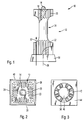
- Exposed light curing device 10 has a heat sink 12 which is arranged in the course of the gun-shaped light curing device.
- a battery pack and a release button is mounted in the handle of the light curing device, and on the upper side in addition a display device for displaying the operating state of the trained as a hand-held light curing device.
- the heat sink 12 carries according to the invention a light source 14 at its front end.
- the light source 14 is designed as an LED or as a multiple arrangement of LEDs and emits both light and heat.
- the emitted light output is conducted via a light guide - possibly with the aid of reflectors - in the mouth of the patient when the dentist performs the light curing of the dental restoration part.
- the heat sink 12 has a centrally extending heat conductor bar 18 as the copper core, so that the heat is dissipated particularly well in the axial direction of the elongate heat sink 12.
- the heat sink 12 has a substantially dumbbell-like construction.
- cooling ribs 20 extend in a star-shaped manner.
- star-shaped cooling ribs 22 extend, while between the front and the rear cooling ribs 20 and 22 a recess 24 is provided which extends extends circularly and offers a free space.
- All cooling fins 20 and 22 extend parallel to an axis 26 of the heat sink 12, which coincides with the optical axis of the light source 14.
- the cooling fins 22 are substantially longer in the axial direction than the cooling fins 20. While each cooling fin 20 is about as long as it is high, the cooling fins 22 occupy at least about one third of the total length of the heat sink 12.
- a fan 30 is flanged, which passes a cooling air flow 32 through the heat sink 12.
- the cooling air flow sweeps along the cooling fins 20 and 22 and also passes through the recess 24. It is as Compressed air flow formed, as explained in detail below.
- the heat sink 12 has in the front of the Fig. 2 apparent cooling fins 20. Through the longitudinally extending cooling fins 20 and 22 through the blower 30 is visible with its flow outlet.
- the light curing device has the heat sink 12 surrounding printed circuit boards 34, 36, 38 and 40, which extend in so far substantially cuboid.
- the printed circuit boards completely surround the heat sink 12 and to this extent form a flow channel for the provision of the cooling air flow through the heat sink.
- the fan 30 has two opposing air inlet slots 42, which are left in a rear wall 44 of the blower housing. In known manner, the blower 30 is driven by an electric motor 46.
- FIG. 4 can be seen in which way the structure of heat sink and PCB can be mounted.
- a front printed circuit board 50 surrounds the light source 14, which is connected via a substrate 52 with the heat conduction bar 18, not shown.
- the substantially axially parallel extending printed circuit boards are hinged.
- one joint is provided, in Fig. 4 the joints 54 and 56 are shown by way of example.
- the printed circuit board 34 is shown in the pivoted state, while the printed circuit boards 36 and 38 are shown in the assembled state.
- the printed circuit boards each carry components, wherein for the printed circuit board 34 by way of example a plurality of components 60 is shown.
- the components 60 extend into the recess 24 and are so far in the cooling air flow 32 of the blower 30.
- they are connected in good heat conduction with the printed circuit board 34, on the large area also sweeps along cooling air.
- copper conductor also results in a good cooling of the components 60th
- the printed circuit boards 34 to 40 do not extend exactly cuboid, but slightly tapered forward. As a result, the flow cross-section in the region of the rear cooling ribs 22 is greater and lower in the region of the front cooling ribs 20. Accordingly, the flow velocity is greater in the front, hot region, while more time remains in the rear region for the cooling air to absorb the heat.
- FIG. 5 it can be seen how the cooling air flow 32 is deflected.
- the cooling air is first introduced into the heat sink via the fan 64 and flows forward, that is to say in the direction of the light source 14.
- a deflection 70 for the cooling air flow is provided in the front corners of the substantially cuboidal printed circuit board arrangement. Accordingly, in the front corners, the printed circuit board arrangement has practically relatively large and wide slots, which allow a deflection of the cooling air flow to the rear.
- the cooling air flow accordingly extends to the rear, corresponding to the arrows 72.
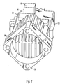
- the heat sink 12 has a heat conducting rod 80, which extends substantially parallelepipedally from solid, good heat-conducting metal along and is provided for receiving the light source on its front end face 82.
- the light source adjacent no additional cooling fin arrangement is provided.
- the Fig. 6 is not apparent and has at its rear region on the cooling ribs 22, which are so far with extremely low thermal resistance associated with the light source.
- the blower 30 is mounted, whose outer circumference substantially corresponds to the extent of the cooling fins, so that a compact unit of the heat sink 12 and the blower 30 is formed. It is particularly advantageous that the substantially square housing of the blower 30 is arranged at an angle of approximately 45 ° to the transverse extent of the furnishedleitstab 80, so that via a flange 84, the fan 30 is well fastened and still the cooling fins 22 on practically the entire effective area of the blower 30 extend.
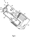
- Fig. 7 Furthermore, it is provided that it is provided that it is provided that it is provided that the heat-conducting rod 80 are provided over a large area printed circuit boards, of which the printed circuit boards 34, 36 and 38 from FIG. 7 can be seen, wherein the components 60 extend in this embodiment, on the side remote from the heat sink side of the printed circuit boards 34 to 38. This allows a large-area heat conduction connection between the printed circuit boards 34 to 38 and the nuclearleitstab 80, so that a solid state cooling for the components 60 can be realized.
- the components 60 are also in this embodiment in the cooling air flow, and it is preferable to arrange the particularly heat-sensitive devices 60 on the printed circuit board 36 and the printed circuit board 40, which are fully in the cooling air flow, while the cooling air flow for the components on the printed circuit boards 34 and 38th is provided only as a secondary air flow.
- the light source 14 can be applied to the end face 82 of the heat conducting rod 80.
- the light source 14 has five cross-shaped LED chips mounted on a common substrate 90, which is in large contact with the end face 82, so that the heat generated by the light source 14 with very low thermal resistance in the Thermal Conductor 80 is initiated.
- the printed circuit boards 36 and 40 are pulled over the substrate 90 to the front so that they provide terminal lugs 92, which are available for contacting the front printed circuit board, not shown, on the substrate 90 for the supply of the light source.
- the front-printed circuit board then extends between the terminal lugs 92 of the opposing printed circuit boards 36 and 40th
- the introduced heat is additionally passed via these tracks in the rear area, where by the intense cooling air flow, which is generated by the blower 30, the cooling for the printed circuit boards 36 and 40 is realized areally.
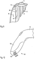
- the cooling air flow is preferably deflected in order to achieve the desired cooling, in particular also of the components 60.
- the cooling air flow is deflected in the region of a deflection 94, which is adjacent to the light source 14, to a second cooling air channel 96.
- the air flows along the inside of the housing and enters - as it is Fig. 10 can be seen - at the rear end 98 of cooling air slots 100 from a handle 102 of the prismatic light curing device 10 from.
Landscapes
- Health & Medical Sciences (AREA)
- Oral & Maxillofacial Surgery (AREA)
- Dentistry (AREA)
- Epidemiology (AREA)
- Life Sciences & Earth Sciences (AREA)
- Animal Behavior & Ethology (AREA)
- General Health & Medical Sciences (AREA)
- Public Health (AREA)
- Veterinary Medicine (AREA)
- Cooling Or The Like Of Electrical Apparatus (AREA)
- Polymerisation Methods In General (AREA)
Claims (18)
- Dispositif de photopolymérisation en forme de pistolet, avec un dissipateur thermique allongé (12), qui est disposé dans le canon du dispositif de photopolymérisation en forme de pistolet et porte une source de lumière LED sur sa face avant, qui est connecté indirectement ou directement, avec une tige métallique conductrice de chaleur (18 ; 80), qui s'étend centralement à l'intérieur du dissipateur thermique (12) et possède un noyau de cuivre, où la tige conductrice de chaleur (18 ; 80) est mise en liaison de conduction thermique au moins avec sa zone d'extrémité détournée de la source de lumière (14) avec des ailettes de refroidissement (20, 22) du dissipateur thermique (12), afin que la chaleur produite par la source de lumière (14) puisse être dissipée dans le sens axial du dissipateur thermique allongé (12), où une déviation pour un flux d'air de refroidissement (32) est fournie avoisinant la source de lumière (14) entre deux parties du boîtier ou entre au moins une carte de circuit imprimé (34, 36, 38, 40) et un boitier, à travers de laquelle le flux d'air de refroidissement (32) sera dévié au moins 90°, et où le flux d'air de refroidissement (32) passe d'abord un premier conduit d'air de refroidissement (92) et après la déviation (70, 94) un deuxième conduit d'air de refroidissement (96) ou vice versa, et où une soufflerie (30) est disposée sur la face avant du dissipateur thermique (12) éloigné de la source de lumière (14).
- Dispositif de photopolymérisation selon la revendication 1, caractérisé en ce que l'unité de photopolymérisation (60) présente des composants, qui se trouvent en particulier à côté de la tige conductrice de chaleur sur au moins une carte de circuit imprimé.
- Dispositif de photopolymérisation selon la revendication 2, caractérisé en ce qu'au moins les composants (60) se trouvent à une position libre d'ailettes de refroidissement, où le dissipateur thermique (12) est réalisé de telle sorte que, dans sa partie avant, avoisinant la source de lumière (14) et dans sa partie arrière des ailettes de refroidissement (20, 22) s'étendent en forme d'étoile. où entre les ailettes de refroidissement (20, 22) un évidement (24) à peu près circulaire définit l'endroit libre d'ailettes de refroidissement.
- Dispositif de photopolymérisation selon l'une des revendications 1 ou 2, caractérisé en ce qu'au moins une carte de circuit imprimé (34, 36, 38, 40) est apposée sur la tige métallique conductrice de chaleur (80) du dissipateur thermique (12), qui est constitué de métal solide, conductrice de chaleur, et y est isolé et en particulier est en liaison de conduction thermique avec celui-ci.
- Dispositif de photopolymérisation selon la revendication 4, caractérisé en ce que la tige métallique conductrice de chaleur (80), est essentiellement formée comme parallélépipède et en particulier est entourée sur les quatre côtés par des cartes de circuits imprimés (34, 36, 38, 40) et sur sa zone arrière présente les ailettes de refroidissement (22).
- Dispositif de photopolymérisation selon l'une des revendications 2 à 5, caractérisé en ce que les composants (60) et/ou les cartes de circuits imprimés (34, 36, 38, 40) sont disposés entourant au moins partiellement le dissipateur thermique (12).
- Dispositif de photopolymérisation selon l'une des revendications 2 à 5, caractérisé en ce que les composants (60) et/ou les cartes des circuits Imprimés sont accueillis dans des espaces radiaux libres, qui sont limitées par les ailettes de refroidissement (20, 22) du dissipateur thermique (12) et un noyau du dissipateur thermique (12).
- Dispositif de photopolymérisation selon l'une des revendications précédentes, caractérisé en ce qu'au moins une carte de circuit Imprimé est au moins partiellement montée sur le dissipateur thermique (12) et s'étend en particulier latéralement le long du dissipateur thermique (12).
- Dispositif de photopolymérisation selon l'une des revendications précédentes, caractérisé en ce qu'au moins trois cartes de circuits imprimés (34, 36, 38,40), en particulier les PCB quatre (34, 36, 38, 40), entourent le dissipateur thermique (12).
- Dispositif de photopolymérisation selon l'une des revendications précédentes, caractérisées en ce qu'au moins une carte de circuit imprimé (34, 36, 38, 40) est montée mobile en face d'une autre carte de circuit Imprimé (34, 36, 38, 40), en particulier est montée pivotant.
- Dispositif de photopolymérisation selon l'une des revendications 2 à 10, caractérisé en ce que la carte de circuit imprimé porte, en particulier tous les composants (60) sur sa face tournée vers le dissipateur thermique (12) ou sur sa face détournée du dissipateur thermique (12).
- Dispositif de photopolymérisation selon l'une des revendications 2 à 11, caractérisé en ce que les composants (60) se trouvent en liaison de conduction thermique avec la carte de circuit Imprimé et la carte de circuit imprimé est formée comme élément de refroidissement, par lequel la chaleur dégagée par les composants (60) et introduite dans la carte de circuit imprimé peut être émise par l'air de refroidissement (32).
- Dispositif de photopolymérisation selon l'une des revendications précédentes, caractérisé en ce que le premier conduit d'air de refroidissement s'étend entre au moins une carte de circuit imprimé (34,36, 38,40) et la tige conductrice de chaleur (18) et/ou le dissipateur thermique (12).
- Dispositif de photopolymérisation selon l'une des revendications s précédentes, caractérisé en ce que le deuxième conduit d'air de refroidissement s'étend entre les cartes de circuits imprimés (34, 36, 38, 40) et un boîtier de l'appareil de photopolymérisation ou entre deux pièces du boîtier de l'appareil de photopolymérisation.
- Dispositif de photopolymérisation selon l'une des revendications 2 à 14, caractérisé en ce que l'air de refroidissement d'une soufflerie alimente les ailettes de refroidissement (20, 22) et en particulier aussi les composants (60).
- Dispositif de photopolymérisation selon l'une des revendications précédentes, caractérisé en ce que le flux d'air de refroidissement après avoir passé les deux conduits d'air de refroidissement (92, 96) quitte le boîtier dans une extrémité d'une poignée de l'appareil de photopolymérisation.
- Dispositif de photopolymérisation selon l'une des revendications précédentes, caractérisé en ce que deux cartes de circuit Imprimé (34, 36, 38, 40) l'une en face de l'autre dépassent la source de lumière (14) et établissent un contact avec les languettes de raccordement d'une carte de circuit Imprimé frontale, qui s'étend essentiellement perpendiculairement aux cartes de circuits imprimés (34, 36, 38, 40) et par lequel la source lumineuse (14) est connectée.
- Dispositif de photopolymérisation selon l'une des revendications précédentes, caractérisé en ce que la tige métallique conductrice de chaleur (18 ; 80) est fabriquée en cuivre et le dissipateur thermique (12) en particulier est fabriqué en aluminium ou en un alliage d'aluminium.
Applications Claiming Priority (1)
| Application Number | Priority Date | Filing Date | Title |
|---|---|---|---|
| DE102006036828A DE102006036828B3 (de) | 2006-08-07 | 2006-08-07 | Lichthärtgerät |
Publications (2)
| Publication Number | Publication Date |
|---|---|
| EP1886643A1 EP1886643A1 (fr) | 2008-02-13 |
| EP1886643B1 true EP1886643B1 (fr) | 2018-04-04 |
Family
ID=38686630
Family Applications (1)
| Application Number | Title | Priority Date | Filing Date |
|---|---|---|---|
| EP07009726.6A Not-in-force EP1886643B1 (fr) | 2006-08-07 | 2007-05-15 | Appareil de durcissement à la lumière |
Country Status (5)
| Country | Link |
|---|---|
| US (1) | US7976307B2 (fr) |
| EP (1) | EP1886643B1 (fr) |
| JP (1) | JP4861268B2 (fr) |
| DE (1) | DE102006036828B3 (fr) |
| ES (1) | ES2676082T3 (fr) |
Families Citing this family (14)
| Publication number | Priority date | Publication date | Assignee | Title |
|---|---|---|---|---|
| US7846391B2 (en) | 2006-05-22 | 2010-12-07 | Lumencor, Inc. | Bioanalytical instrumentation using a light source subsystem |
| US8098375B2 (en) | 2007-08-06 | 2012-01-17 | Lumencor, Inc. | Light emitting diode illumination system |
| CN101373064B (zh) * | 2007-08-24 | 2011-05-11 | 富准精密工业(深圳)有限公司 | 发光二极管灯具 |
| DE102008033556A1 (de) * | 2008-03-14 | 2009-09-17 | Kaltenbach & Voigt Gmbh | Lichtquelle für ein zahnmedizinisches Gerät |
| US9763760B2 (en) | 2008-07-01 | 2017-09-19 | Ivoclar Vivadent Ag | Apparatus for light-curing a dental object |
| DE102008031094A1 (de) * | 2008-07-01 | 2010-01-07 | Ivoclar Vivadent Ag | Gerät zum Lichthärten eines Dentalobjekts |
| US8242462B2 (en) | 2009-01-23 | 2012-08-14 | Lumencor, Inc. | Lighting design of high quality biomedical devices |
| TWI467115B (zh) * | 2010-08-06 | 2015-01-01 | Ind Tech Res Inst | 具高散熱效能之光源裝置 |
| US8475285B2 (en) | 2011-08-04 | 2013-07-02 | Megatouch, Llc | Swinging motherboard for amusement device |
| US9217561B2 (en) | 2012-06-15 | 2015-12-22 | Lumencor, Inc. | Solid state light source for photocuring |
| JP6153369B2 (ja) * | 2013-04-05 | 2017-06-28 | 日立マクセル株式会社 | 美容器具 |
| US10159548B2 (en) | 2014-09-17 | 2018-12-25 | Garrison Dental Solutions, L.L.C. | Dental curing light |
| USD810293S1 (en) | 2017-01-20 | 2018-02-13 | Garrison Dental Solutions, Llc | Dental instrument |
| CZ310301B6 (cs) * | 2019-09-16 | 2025-02-05 | PO LIGHTING CZECH s.r.o. | Světelné zařízení pro motorové vozidlo |
Family Cites Families (24)
| Publication number | Priority date | Publication date | Assignee | Title |
|---|---|---|---|---|
| DE8135468U1 (de) * | 1981-12-05 | 1982-04-15 | Kulzer & Co Gmbh, 6380 Bad Homburg | "dental-photopolymerisationsgeraet" |
| US4470101A (en) * | 1982-09-29 | 1984-09-04 | Simmonds Precision Products, Inc. | Apparatus for the mounting and wiring of printed circuit boards |
| DE3719561C2 (de) * | 1986-06-12 | 1998-12-10 | Morita Mfg | Medizinisches Lichtbestrahlungshandstück |
| JP2713628B2 (ja) * | 1990-03-19 | 1998-02-16 | 富士通株式会社 | 表面実装型icパッケージの放熱構造 |
| JPH1027926A (ja) * | 1996-07-11 | 1998-01-27 | Nichia Chem Ind Ltd | 光半導体装置 |
| CN1276917A (zh) * | 1997-09-25 | 2000-12-13 | 布里斯托尔大学 | 光学辐照装置 |
| US6200134B1 (en) * | 1998-01-20 | 2001-03-13 | Kerr Corporation | Apparatus and method for curing materials with radiation |
| US6068474A (en) * | 1998-01-30 | 2000-05-30 | Ivoclar Ag | Light curing device |
| DE19803755C2 (de) * | 1998-01-30 | 2001-03-15 | Ivoclar Ag Schaan | Lichthärtgerät |
| DE19943393C1 (de) * | 1999-09-10 | 2001-01-25 | Espe Dental Ag | Bestrahlungsgerät für Dentalwerkstoffe |
| US6171105B1 (en) * | 1999-09-21 | 2001-01-09 | Eg&G Ilc Technology, Inc. | Dental-restoration light-curing system |
| JP4461584B2 (ja) * | 1999-11-16 | 2010-05-12 | パナソニック株式会社 | ヒートシンク装置 |
| US7320593B2 (en) * | 2000-03-08 | 2008-01-22 | Tir Systems Ltd. | Light emitting diode light source for curing dental composites |
| JP2001327517A (ja) * | 2000-05-24 | 2001-11-27 | Sakoguchi:Kk | レジン硬化用機器 |
| DE10127416B4 (de) * | 2001-06-06 | 2008-01-03 | Ivoclar Vivadent Ag | Lichthärtgerät sowie Lichtquelle mit einer Mehrzahl von LED's und einem Kühlkörper |
| EP1282206A1 (fr) * | 2001-07-30 | 2003-02-05 | Agilent Technologies, Inc. (a Delaware corporation) | Méthode et dispositif pour le refroidissement des dispositifs électroniques et opto-électroniques |
| DE10214366B4 (de) | 2002-03-30 | 2017-03-16 | Robert Bosch Gmbh | Messanordnung |
| US7182597B2 (en) * | 2002-08-08 | 2007-02-27 | Kerr Corporation | Curing light instrument |
| AU2003298561A1 (en) * | 2002-08-23 | 2004-05-13 | Jonathan S. Dahm | Method and apparatus for using light emitting diodes |
| DE10242366B4 (de) * | 2002-09-12 | 2010-10-21 | Ivoclar Vivadent Ag | Lichthärtgerät zum Aushärten von lichthärtbaren Materialien |
| US6890175B2 (en) * | 2002-12-18 | 2005-05-10 | Ultradent Products, Inc. | Cooling system for hand-held curing light |
| US6918762B2 (en) * | 2003-03-21 | 2005-07-19 | Kerr Corporation | Light-generating instrument |
| KR100643516B1 (ko) * | 2003-05-06 | 2006-11-10 | 가부시키가이샤 모리타 세이사쿠쇼 | 의료용 광조사장치 |
| DE10320141B4 (de) * | 2003-05-06 | 2010-11-25 | Ivoclar Vivadent Ag | Lichtpolymerisationsgerät |
-
2006
- 2006-08-07 DE DE102006036828A patent/DE102006036828B3/de not_active Expired - Fee Related
-
2007
- 2007-05-15 ES ES07009726.6T patent/ES2676082T3/es active Active
- 2007-05-15 EP EP07009726.6A patent/EP1886643B1/fr not_active Not-in-force
- 2007-08-07 JP JP2007205992A patent/JP4861268B2/ja not_active Expired - Fee Related
- 2007-08-16 US US11/893,526 patent/US7976307B2/en active Active
Non-Patent Citations (1)
| Title |
|---|
| None * |
Also Published As
| Publication number | Publication date |
|---|---|
| US7976307B2 (en) | 2011-07-12 |
| JP4861268B2 (ja) | 2012-01-25 |
| DE102006036828B3 (de) | 2008-04-17 |
| US20080032254A1 (en) | 2008-02-07 |
| JP2008038155A (ja) | 2008-02-21 |
| EP1886643A1 (fr) | 2008-02-13 |
| ES2676082T3 (es) | 2018-07-16 |
Similar Documents
| Publication | Publication Date | Title |
|---|---|---|
| EP1886643B1 (fr) | Appareil de durcissement à la lumière | |
| DE102008051256B4 (de) | Halbleiter-Strahlungsquelle | |
| DE102015209375B4 (de) | Kühlvorrichtung und Wechselrichtergehäuse mit einer solchen Kühlvorrichtung | |
| DE102019114885B3 (de) | Vorrichtung zur Wärmeableitung aus einer endoskopischen Beleuchtungseinrichtung | |
| EP1398005B1 (fr) | Appareil de photopolymérisation | |
| DE102014105960B4 (de) | LED- Beleuchtungseinrichtung mit einem verbesserten Kühlkörper | |
| DE102008060613B4 (de) | Kühlanordnung für einen in einem Schaltschrank angeordneten Umrichter | |
| EP1995514A2 (fr) | Unité d'éclairage | |
| DE102009049683A1 (de) | Led-Beleuchtungsmodul | |
| EP2003744A1 (fr) | Appareil laser refroidi au gaz pour sources de rayonnement laser très compactes | |
| WO2002033264A1 (fr) | Installation de ventilation | |
| WO2013135527A1 (fr) | Lampe à diodes électroluminescentes et procédé de fabrication d'une lampe à diodes électroluminescentes | |
| EP1637234A1 (fr) | Dispositif de soudage par extrusion portable | |
| DE102010040399A1 (de) | Gehäuse zur Aufnahme eines elektrischen Antriebs | |
| DE10127416B4 (de) | Lichthärtgerät sowie Lichtquelle mit einer Mehrzahl von LED's und einem Kühlkörper | |
| DE102006057796B4 (de) | Kühlanordnung für Wärme erzeugende elektrische Komponenten und elektrisches Gerät damit | |
| EP2114116B1 (fr) | Refroidissement hybride | |
| DE10320141B4 (de) | Lichtpolymerisationsgerät | |
| WO2006105834A2 (fr) | Unite de refroidissement | |
| DE102005007545B4 (de) | Vorrichtung und Verfahren zur Kühlung einer Elektronik | |
| DE8816682U1 (de) | Bestrahlungsgerät | |
| EP1731862A1 (fr) | Source lumineuse pour l'endoscopie et la microscopie | |
| EP1104079A2 (fr) | Moteur électrique, en particulier pour une pompe centrifuge | |
| DE102019129815B4 (de) | Kühlvorrichtung für ein Endoskop oder Exoskop | |
| WO2007028672A1 (fr) | Corps de refroidissement pour boitier electronique |
Legal Events
| Date | Code | Title | Description |
|---|---|---|---|
| PUAI | Public reference made under article 153(3) epc to a published international application that has entered the european phase |
Free format text: ORIGINAL CODE: 0009012 |
|
| AK | Designated contracting states |
Kind code of ref document: A1 Designated state(s): AT BE BG CH CY CZ DE DK EE ES FI FR GB GR HU IE IS IT LI LT LU LV MC MT NL PL PT RO SE SI SK TR |
|
| AX | Request for extension of the european patent |
Extension state: AL BA HR MK YU |
|
| 17P | Request for examination filed |
Effective date: 20080225 |
|
| AKX | Designation fees paid |
Designated state(s): AT BE BG CH CY CZ DE DK EE ES FI FR GB GR HU IE IS IT LI LT LU LV MC MT NL PL PT RO SE SI SK TR |
|
| 17Q | First examination report despatched |
Effective date: 20110816 |
|
| GRAP | Despatch of communication of intention to grant a patent |
Free format text: ORIGINAL CODE: EPIDOSNIGR1 |
|
| INTG | Intention to grant announced |
Effective date: 20171024 |
|
| RIN1 | Information on inventor provided before grant (corrected) |
Inventor name: PLANK, WOLFGANG Inventor name: SENN, BRUNO |
|
| GRAS | Grant fee paid |
Free format text: ORIGINAL CODE: EPIDOSNIGR3 |
|
| GRAA | (expected) grant |
Free format text: ORIGINAL CODE: 0009210 |
|
| AK | Designated contracting states |
Kind code of ref document: B1 Designated state(s): AT BE BG CH CY CZ DE DK EE ES FI FR GB GR HU IE IS IT LI LT LU LV MC MT NL PL PT RO SE SI SK TR |
|
| REG | Reference to a national code |
Ref country code: GB Ref legal event code: FG4D Free format text: NOT ENGLISH |
|
| REG | Reference to a national code |
Ref country code: CH Ref legal event code: EP |
|
| REG | Reference to a national code |
Ref country code: AT Ref legal event code: REF Ref document number: 984742 Country of ref document: AT Kind code of ref document: T Effective date: 20180415 |
|
| REG | Reference to a national code |
Ref country code: DE Ref legal event code: R096 Ref document number: 502007016132 Country of ref document: DE |
|
| REG | Reference to a national code |
Ref country code: IE Ref legal event code: FG4D Free format text: LANGUAGE OF EP DOCUMENT: GERMAN |
|
| REG | Reference to a national code |
Ref country code: FR Ref legal event code: PLFP Year of fee payment: 12 |
|
| REG | Reference to a national code |
Ref country code: ES Ref legal event code: FG2A Ref document number: 2676082 Country of ref document: ES Kind code of ref document: T3 Effective date: 20180716 |
|
| REG | Reference to a national code |
Ref country code: SE Ref legal event code: TRGR |
|
| REG | Reference to a national code |
Ref country code: NL Ref legal event code: MP Effective date: 20180404 |
|
| REG | Reference to a national code |
Ref country code: LT Ref legal event code: MG4D |
|
| PG25 | Lapsed in a contracting state [announced via postgrant information from national office to epo] |
Ref country code: NL Free format text: LAPSE BECAUSE OF FAILURE TO SUBMIT A TRANSLATION OF THE DESCRIPTION OR TO PAY THE FEE WITHIN THE PRESCRIBED TIME-LIMIT Effective date: 20180404 |
|
| PG25 | Lapsed in a contracting state [announced via postgrant information from national office to epo] |
Ref country code: FI Free format text: LAPSE BECAUSE OF FAILURE TO SUBMIT A TRANSLATION OF THE DESCRIPTION OR TO PAY THE FEE WITHIN THE PRESCRIBED TIME-LIMIT Effective date: 20180404 Ref country code: BG Free format text: LAPSE BECAUSE OF FAILURE TO SUBMIT A TRANSLATION OF THE DESCRIPTION OR TO PAY THE FEE WITHIN THE PRESCRIBED TIME-LIMIT Effective date: 20180704 Ref country code: PL Free format text: LAPSE BECAUSE OF FAILURE TO SUBMIT A TRANSLATION OF THE DESCRIPTION OR TO PAY THE FEE WITHIN THE PRESCRIBED TIME-LIMIT Effective date: 20180404 Ref country code: LT Free format text: LAPSE BECAUSE OF FAILURE TO SUBMIT A TRANSLATION OF THE DESCRIPTION OR TO PAY THE FEE WITHIN THE PRESCRIBED TIME-LIMIT Effective date: 20180404 |
|
| PG25 | Lapsed in a contracting state [announced via postgrant information from national office to epo] |
Ref country code: LV Free format text: LAPSE BECAUSE OF FAILURE TO SUBMIT A TRANSLATION OF THE DESCRIPTION OR TO PAY THE FEE WITHIN THE PRESCRIBED TIME-LIMIT Effective date: 20180404 Ref country code: GR Free format text: LAPSE BECAUSE OF FAILURE TO SUBMIT A TRANSLATION OF THE DESCRIPTION OR TO PAY THE FEE WITHIN THE PRESCRIBED TIME-LIMIT Effective date: 20180705 |
|
| PG25 | Lapsed in a contracting state [announced via postgrant information from national office to epo] |
Ref country code: PT Free format text: LAPSE BECAUSE OF FAILURE TO SUBMIT A TRANSLATION OF THE DESCRIPTION OR TO PAY THE FEE WITHIN THE PRESCRIBED TIME-LIMIT Effective date: 20180806 |
|
| REG | Reference to a national code |
Ref country code: DE Ref legal event code: R097 Ref document number: 502007016132 Country of ref document: DE |
|
| REG | Reference to a national code |
Ref country code: BE Ref legal event code: MM Effective date: 20180531 |
|
| PG25 | Lapsed in a contracting state [announced via postgrant information from national office to epo] |
Ref country code: DK Free format text: LAPSE BECAUSE OF FAILURE TO SUBMIT A TRANSLATION OF THE DESCRIPTION OR TO PAY THE FEE WITHIN THE PRESCRIBED TIME-LIMIT Effective date: 20180404 Ref country code: EE Free format text: LAPSE BECAUSE OF FAILURE TO SUBMIT A TRANSLATION OF THE DESCRIPTION OR TO PAY THE FEE WITHIN THE PRESCRIBED TIME-LIMIT Effective date: 20180404 Ref country code: RO Free format text: LAPSE BECAUSE OF FAILURE TO SUBMIT A TRANSLATION OF THE DESCRIPTION OR TO PAY THE FEE WITHIN THE PRESCRIBED TIME-LIMIT Effective date: 20180404 Ref country code: CZ Free format text: LAPSE BECAUSE OF FAILURE TO SUBMIT A TRANSLATION OF THE DESCRIPTION OR TO PAY THE FEE WITHIN THE PRESCRIBED TIME-LIMIT Effective date: 20180404 Ref country code: MC Free format text: LAPSE BECAUSE OF FAILURE TO SUBMIT A TRANSLATION OF THE DESCRIPTION OR TO PAY THE FEE WITHIN THE PRESCRIBED TIME-LIMIT Effective date: 20180404 Ref country code: SK Free format text: LAPSE BECAUSE OF FAILURE TO SUBMIT A TRANSLATION OF THE DESCRIPTION OR TO PAY THE FEE WITHIN THE PRESCRIBED TIME-LIMIT Effective date: 20180404 |
|
| PLBE | No opposition filed within time limit |
Free format text: ORIGINAL CODE: 0009261 |
|
| STAA | Information on the status of an ep patent application or granted ep patent |
Free format text: STATUS: NO OPPOSITION FILED WITHIN TIME LIMIT |
|
| REG | Reference to a national code |
Ref country code: IE Ref legal event code: MM4A |
|
| 26N | No opposition filed |
Effective date: 20190107 |
|
| PG25 | Lapsed in a contracting state [announced via postgrant information from national office to epo] |
Ref country code: LU Free format text: LAPSE BECAUSE OF NON-PAYMENT OF DUE FEES Effective date: 20180515 |
|
| PG25 | Lapsed in a contracting state [announced via postgrant information from national office to epo] |
Ref country code: IE Free format text: LAPSE BECAUSE OF NON-PAYMENT OF DUE FEES Effective date: 20180515 |
|
| PG25 | Lapsed in a contracting state [announced via postgrant information from national office to epo] |
Ref country code: SI Free format text: LAPSE BECAUSE OF FAILURE TO SUBMIT A TRANSLATION OF THE DESCRIPTION OR TO PAY THE FEE WITHIN THE PRESCRIBED TIME-LIMIT Effective date: 20180404 Ref country code: BE Free format text: LAPSE BECAUSE OF NON-PAYMENT OF DUE FEES Effective date: 20180531 |
|
| PGFP | Annual fee paid to national office [announced via postgrant information from national office to epo] |
Ref country code: DE Payment date: 20190410 Year of fee payment: 13 Ref country code: IT Payment date: 20190329 Year of fee payment: 13 Ref country code: ES Payment date: 20190604 Year of fee payment: 13 |
|
| PGFP | Annual fee paid to national office [announced via postgrant information from national office to epo] |
Ref country code: SE Payment date: 20190412 Year of fee payment: 13 Ref country code: FR Payment date: 20190412 Year of fee payment: 13 |
|
| PGFP | Annual fee paid to national office [announced via postgrant information from national office to epo] |
Ref country code: CH Payment date: 20190509 Year of fee payment: 13 |
|
| PGFP | Annual fee paid to national office [announced via postgrant information from national office to epo] |
Ref country code: AT Payment date: 20190411 Year of fee payment: 13 Ref country code: GB Payment date: 20190412 Year of fee payment: 13 |
|
| PG25 | Lapsed in a contracting state [announced via postgrant information from national office to epo] |
Ref country code: MT Free format text: LAPSE BECAUSE OF FAILURE TO SUBMIT A TRANSLATION OF THE DESCRIPTION OR TO PAY THE FEE WITHIN THE PRESCRIBED TIME-LIMIT Effective date: 20180404 |
|
| PG25 | Lapsed in a contracting state [announced via postgrant information from national office to epo] |
Ref country code: TR Free format text: LAPSE BECAUSE OF FAILURE TO SUBMIT A TRANSLATION OF THE DESCRIPTION OR TO PAY THE FEE WITHIN THE PRESCRIBED TIME-LIMIT Effective date: 20180404 |
|
| PG25 | Lapsed in a contracting state [announced via postgrant information from national office to epo] |
Ref country code: HU Free format text: LAPSE BECAUSE OF FAILURE TO SUBMIT A TRANSLATION OF THE DESCRIPTION OR TO PAY THE FEE WITHIN THE PRESCRIBED TIME-LIMIT; INVALID AB INITIO Effective date: 20070515 |
|
| PG25 | Lapsed in a contracting state [announced via postgrant information from national office to epo] |
Ref country code: CY Free format text: LAPSE BECAUSE OF FAILURE TO SUBMIT A TRANSLATION OF THE DESCRIPTION OR TO PAY THE FEE WITHIN THE PRESCRIBED TIME-LIMIT Effective date: 20180404 |
|
| PG25 | Lapsed in a contracting state [announced via postgrant information from national office to epo] |
Ref country code: IS Free format text: LAPSE BECAUSE OF FAILURE TO SUBMIT A TRANSLATION OF THE DESCRIPTION OR TO PAY THE FEE WITHIN THE PRESCRIBED TIME-LIMIT Effective date: 20180804 |
|
| REG | Reference to a national code |
Ref country code: CH Ref legal event code: PFA Owner name: IVOCLAR VIVADENT AG, LI Free format text: FORMER OWNER: IVOCLAR VIVADENT AG, LI |
|
| REG | Reference to a national code |
Ref country code: DE Ref legal event code: R119 Ref document number: 502007016132 Country of ref document: DE |
|
| REG | Reference to a national code |
Ref country code: AT Ref legal event code: MM01 Ref document number: 984742 Country of ref document: AT Kind code of ref document: T Effective date: 20200515 |
|
| PG25 | Lapsed in a contracting state [announced via postgrant information from national office to epo] |
Ref country code: SE Free format text: LAPSE BECAUSE OF NON-PAYMENT OF DUE FEES Effective date: 20200516 Ref country code: LI Free format text: LAPSE BECAUSE OF NON-PAYMENT OF DUE FEES Effective date: 20200531 Ref country code: CH Free format text: LAPSE BECAUSE OF NON-PAYMENT OF DUE FEES Effective date: 20200531 Ref country code: AT Free format text: LAPSE BECAUSE OF NON-PAYMENT OF DUE FEES Effective date: 20200515 |
|
| GBPC | Gb: european patent ceased through non-payment of renewal fee |
Effective date: 20200515 |
|
| PG25 | Lapsed in a contracting state [announced via postgrant information from national office to epo] |
Ref country code: FR Free format text: LAPSE BECAUSE OF NON-PAYMENT OF DUE FEES Effective date: 20200531 Ref country code: GB Free format text: LAPSE BECAUSE OF NON-PAYMENT OF DUE FEES Effective date: 20200515 |
|
| PG25 | Lapsed in a contracting state [announced via postgrant information from national office to epo] |
Ref country code: DE Free format text: LAPSE BECAUSE OF NON-PAYMENT OF DUE FEES Effective date: 20201201 |
|
| REG | Reference to a national code |
Ref country code: ES Ref legal event code: FD2A Effective date: 20210930 |
|
| PG25 | Lapsed in a contracting state [announced via postgrant information from national office to epo] |
Ref country code: IT Free format text: LAPSE BECAUSE OF NON-PAYMENT OF DUE FEES Effective date: 20200515 |
|
| PG25 | Lapsed in a contracting state [announced via postgrant information from national office to epo] |
Ref country code: ES Free format text: LAPSE BECAUSE OF NON-PAYMENT OF DUE FEES Effective date: 20200516 |