EP1886777A1 - Défonceuse - Google Patents
Défonceuse Download PDFInfo
- Publication number
- EP1886777A1 EP1886777A1 EP07012771A EP07012771A EP1886777A1 EP 1886777 A1 EP1886777 A1 EP 1886777A1 EP 07012771 A EP07012771 A EP 07012771A EP 07012771 A EP07012771 A EP 07012771A EP 1886777 A1 EP1886777 A1 EP 1886777A1
- Authority
- EP
- European Patent Office
- Prior art keywords
- milling
- milling table
- locking device
- router according
- inclined surface
- Prior art date
- Legal status (The legal status is an assumption and is not a legal conclusion. Google has not performed a legal analysis and makes no representation as to the accuracy of the status listed.)
- Granted
Links
Images




Classifications
-
- B—PERFORMING OPERATIONS; TRANSPORTING
- B27—WORKING OR PRESERVING WOOD OR SIMILAR MATERIAL; NAILING OR STAPLING MACHINES IN GENERAL
- B27C—PLANING, DRILLING, MILLING, TURNING OR UNIVERSAL MACHINES FOR WOOD OR SIMILAR MATERIAL
- B27C5/00—Machines designed for producing special profiles or shaped work, e.g. by rotary cutters; Equipment therefor
- B27C5/10—Portable hand-operated wood-milling machines; Routers
Definitions
- the invention relates to a router having a milling table, which has a milling table upper part and a milling table lower part, which is releasably connected to the milling table upper part and forms a bearing surface with which the router is placed on a workpiece to be milled, and with a milling unit arranged above the milling table with a drive device which has an output shaft, with which a milling tool directed in the axial direction downwards in the connected state is connectable, wherein the milling unit is slidably connected in the axial direction with the milling table, the milling table a passage for the Having passage of the milling tool and at the milling table an accessory, in particular a copying sleeve, with a fastened in the fixed state concentric mounting flange mounting flange is releasably fastened.
- a milling cutter provided with a router on a workpiece By moving a milling cutter provided with a router on a workpiece is obtained on this a the course of the displacement corresponding milling.
- the router can be guided along a milling template so that a correspondingly contoured milling results.
- a copying sleeve is usually used, which is releasably secured with its mounting flange on the milling table and projecting downwards over the milling table bottom, so that the router with fitting to the milling template Copier sleeve can be moved out.
- the milling tool passes through the copy sleeve.
- the present invention is the. Task underlying to create a router of the type mentioned, in which the respective accessory in the simplest possible way can be safely and quickly attached and solved.
- a possible play and vibration-free stop of the additional part should be given at the milling table, which is particularly important for copy sleeves.
- router 1 has on its underside a router table 2, which is formed by a Milling table top 3 and a milling table base 4.
- the underside of the milling table base 4 is formed by a flat bearing surface 5, with which the router 1 is placed on a workpiece to be milled and can be moved on this.
- the router further includes a milling unit 6 arranged above the router table 2 with a drive unit 7 accommodated in an engine head and containing a drive motor 8. A the drive device 7 covering housing part is missing in the drawing.
- the drive motor 8 drives an output shaft directed towards the milling table 2, at the lower end of which a tool holder 10 for interchangeable fastening of a milling tool (not shown) performing the workpiece machining is arranged. In this way, a rotationally fixed connection of the milling tool results with the output shaft.
- the attached milling tool is directed in the axial direction 11 downward.
- the milling unit 6 is connected in the axial direction 11 and thus to the milling table 2 and away from it displaceably with the milling table 2.
- the milling unit 6 is displaceably guided on guide columns 12, 13 projecting from the milling table 2, so that the milling unit 6 can be moved towards the milling table 2 and away from it.
- the guide columns 12, 13 each pass through a guide recess arranged on the milling unit 6, which in the exemplary embodiment is formed by a guide sleeve 14, 15 attached laterally to the milling unit 6.
- the milling unit 6 is acted upon by a spring device, not shown, in the direction of the milling table 2 away.
- the milling unit 6 also has lateral handles 16, 17, on which the user can grasp the milling unit 6.
- the router 1 For milling a workpiece, the router 1 is placed with its milling table 2 on the relevant workpiece, with the milling unit 6 is still so far above the router table 2 that between the milling tool and the workpiece is still a distance. Then you moved the milling unit 6 against the spring force acting on it down and thus the milling tool against the workpiece so that it is processed accordingly. If you want to attach not only a hole in the workpiece but a running in the workpiece surface groove or the like, you move the router 1 on the workpiece.
- a through-passage 18 passing through in the axial direction is arranged for the passage of the milling tool to the workpiece.
- the passage recess 18 is composed of a passage opening 19 of the milling table upper part 3 and a thereto arranged in alignment passage opening 20 of the milling table base 4 together.
- an accessory 21, in the case shown a copy sleeve 22, with a in the fixed state to the passage recess 18 concentric mounting flange 23 are releasably secured.
- the copying sleeve 22 projects from the mounting flange 23 from a circular cylindrical sleeve portion 24 which emerges in the attached state down from the passage recess 18 of the milling table 2 and projects beyond the milling table bottom, so that the router 1 with resting against a milling template sleeve section 24 of the copying sleeve 22nd can be moved.
- the sleeve portion of the attached copy sleeve 22 concentrically surrounds the milling tool.
- the mounting flange 23 is radially outwardly from the sleeve portion 24 from. In the fastened state, the mounting flange 23 is in a direction transverse to the axial direction 11 level and is held between the Milling table top 3 and the Milling base 4.
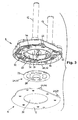
- the milling table base 4 is detachably and removably attached to the bottom of the milling table top 3. To insert the copying sleeve 22 or when the copying sleeve is no longer needed and should be removed, the base table base 4 is removed from the upper table top 3.
- the milling table upper part 3 has a centering receptacle 25, which is accessible from below when the milling table lower part 4 has been removed, for insertion of the fastening flange 23.
- the centering receptacle 25 runs around the passage opening 19 of the milling table upper part 3 around and is of a rear side of the mounting flange 23 associated bearing surface 26 and a peripheral surface 27 associated with the circumference of the fastening flange 23.
- the locking means comprise a arranged on the milling table upper part 3 locking device 28 which is mounted in a substantially transversely to the axial direction 11 stationary transverse plane slidably on the milling table upper part 3 and is acted upon by a spring assembly 29 by a spring force in the locking direction 30 to a locking position , In the drawing, the locking device 28 is in the locking position. The locking device 28 can be moved against the spring force in the locking direction 30 opposite release direction 31 in a release position.
- the locking device 28 is expediently formed by a locking plate 32 having a substantially plate-like shape.
- the locking device 28 For displaceable mounting of the locking device 28 on the milling table upper part 3, the locking device 28, ie in the embodiment, the locking plate 32 in the direction of displacement 30, 31 extending slots 33 which are intervened by fixedly arranged on the milling table upper part 3 guide pin 34 or penetrated.
- the Guide pin 34 are suitably formed by collar bolts. These guide bolts 34, although they sit on the milling table upper part 3, are also shown in FIG.
- the locking device 28 has a U-like embracing shape around the passage opening 19 of the milling table upper part 3. In this case, the locking device 28 is guided both at the end regions of their legs 35, 36 and at its the two legs 35, 36 connecting transition region 37 on the milling table upper part 3.
- locking device could also be designed differently than U-like.
- an actuating device 38 for displacing the locking device 28 against the force of the spring arrangement 29 is arranged on the milling table lower part 4.
- This actuator 38 engages when moving the removed table base 4 against the underside of the upper table top part 3 first on the locking device 28 of the cutter top 3 and moves it in the direction indicated by arrow 31 in its release position. If the lower part of the milling table 4 is moved further against the milling table upper part 3, the actuating device 38 releases the locking device 28 again so that the locking device 28 is displaced by the spring force in the direction indicated by arrow 30 back into its locking position.
- the locking device 28 passes over a detail to be described inclined surface arrangement with the Milling base 4 in engagement, so that the Milling base 4 and thus also the mounting flange 23 of the copy sleeve 22 is held against the Milling table top 3.
- FIG. 6 shows the movement of the milling table lower part 4 against the milling table upper part 3.
- FIG. 7 the end position is reached and the milling table lower part 4 is locked to the milling table upper part 3 while retaining the fastening flange 23.
- the described locking the Milling base 4 with the Milling Top 3 is done automatically when you press the Milling base 4 against the Milling Top 3.
- the locking means are assigned by the user actuable actuating means 39 from the outside, upon actuation of which the locking device 28 is transferred from its illustrated locking position to the release position. In this way, the base table base 4 is unlocked without tools.
- the upper table base 4 and the upper table top 3 off the locking device 28 on a Ein goodseite 40 of the router table 2 Hanger 41, so that the removed Milling base 4 in inclined position ( Figure 6) on the Milling table top 3 hooked and suspended State is pivotable from below against the upper part.
- the arrangement is expediently made such that the locking device 28 is mounted in the direction of the hanger side 40 and away from the latter on the milling table upper part 3.
- the locking device 28 facing in its illustrated locking position of the hanger side 40 and facing away in its release position of the hanger side 40.
- the operating device 38 arranged on the milling table lower part 4 for displacing the locking device 28 in the release direction 31 when the milling table base 4 moves against the milling table upper part 3 is expediently located in the attachment side 40 of the milling table 2 with respect to the passage recess 18. Lower part 4 arranged.
- the above-mentioned inclined surface arrangement, via which the locking device 28 engages with the milling table lower part 4, is expediently also arranged in the attachment side 40 of the milling table 2 with respect to the passage recess 18 opposite region of the milling table 2.
- the oblique surface arrangement has at least one oblique surface (42, 43, 44, 45) which is inclined on the milling table lower part 4 and / or on the milling table upper part 3 with respect to the upper part 3 or the lower part 4 with respect to the transverse plane perpendicular to the axial direction 11. on.
- the locking device 28 expediently contains at least two transverse to their direction of displacement 30, 31 offset from each other inclined surfaces 44, 45, each of which an inclined surface 42, 43 is assigned to the milling table lower part 4. If the locking device 28 moves in the direction of arrow 30 into its locking position, the oblique surfaces 44, 45 of the locking device 28 engage under the inclined surfaces 42, 43 on the milling table lower part 4, so that over the inclined surfaces of the locking device 28, a milling table lower part 4 is pulled against the milling table upper part 3 pulling force is exerted.
- the at least one inclined surface 44, 45 on the locking device 28 falls obliquely downwards.
- the at least one inclined surface 42, 43 on the milling table lower part 4 is directed opposite and rises at the top.
- the locking device 28 When attaching the milling table base 4 to the milling table upper part 3, the locking device 28 is moved in the release direction 31 by means of the actuating device 38. The locking device 28 then assumes such a position that the inclined surfaces 42, 43 of the milling table lower part 4 can pass past the inclined surfaces 44, 45 of the locking device 28 upwards over the inclined surfaces 44, 45 of the locking device 28. If then the locking device 28 moves back into its locking position (arrow 30), engage the inclined surfaces 44, 45 of the locking device 28, the inclined surfaces 42, 43 of the milling table base 4, so that the inclined surfaces 42, 43 of the milling table base 4 on the inclined surfaces 44th , 45 of the locking device 28 slip on.
- the oblique surfaces 44, 45 arranged on the locking device 28 can each be formed by an obliquely bent locking tongue 46, 47.
- a further attacking edge 48 is arranged on which the actuating device 38 of the milling table base 4 during its movement acts against the milling table upper part 3, so that the locking device 28 is displaced in the release direction 31.
- the actuating device 38 is expediently formed by an actuating projection 49 projecting from the milling table lower part 4, an oblique sliding surface 50 assigned to the engaging edge 48 of the locking device 28, and an abutting surface 50 to the milling table -Schteil 4 subsequent subsequent undercut 51 forms, in which the engaging edge 48 forming part of the locking device 28 engages when the sliding surface 50 is above the engaging edge 48, so that the locking device 28 moves due to the action of the spring assembly 29 in its locking position ,
- the operating means 39 serving to remove the milling table lower part 4 from the milling table upper part 3 have a handle 52 arranged outside on the milling table 2 for pivoting an eccentric part 53 which engages the locking device 28 for moving it into the release position.
- the handle 52 is formed by a pivoting handle 44, which is seated on a swivel axis 55 mounted on the milling table upper part 3, on whose region of the handle 52 the eccentric part 53 is arranged.
- the actuating means 39 are acted upon by a spring 56 which is fixedly supported on the upper side of the milling table 3 in such a way that the eccentric part 53 is held in its inoperative position which does not act on the locking device 28. If, in FIG. 5, the handle 52 is pivoted in the clockwise direction, the eccentric part 53 arrives at the point 57 adjacent to the engaging edge 48 to bear against the locking device 28 and presses it into the release position.
- the Aufgleit Structure 50 of the actuating projection 49 of the milling table base 4 associated with the attack edge 48 and the point of application 57 of the Exzenterteils 53 is formed by the edge of an opening 58 of the locking device 28.
- the upper part of the milling table 4 has, on its upper side facing the upper side of the milling table 3, a mounting plate 59 on which the inclined surfaces 42, 43 of the milling table lower part 4 cooperating with the inclined surfaces 44, 45 of the locking device 28 are arranged.
- the mounting plate 59 is suitably made of metal.
- the locking plate 32 of the locking device 28 is suitably made of metal.
- the inclined surfaces 42, 43 of the milling table lower part 4 are each formed by an obliquely bent locking tongue 60, 61 of the mounting plate 59.
- the milling table lower part 4 is mounted on the hanger side 40 of the milling table 2 on the milling table upper part 3.
- the existing hooking means 41 have two on the upper side of the milling table 3 at a distance from each other arranged Ein sustege 62, 63, which in each case one arranged on the milling table lower part 4 inclined surface 64, 65 is assigned to the milling table lower part 4.
- the arrangement could also be reversed so that the Ein rehabilitationstege the milling table lower part and the inclined surfaces are arranged on the milling table upper part.
- the two Ein von strain 62, 63 and the associated inclined surfaces 64, 65 are offset in the direction transverse to the direction of displacement of the locking device 28 to each other.
- the locking tongues 60, 61 of the mounting plate 59 and the Ein vonzept 66, 67 of the mounting plate 59 have, as can be seen in particular from Figure 2, in opposite directions.
- the actuating projection 38 can also be formed by the mounting plate 59 and thereby by an upwardly bent portion of the mounting plate 59.
- the spring assembly 29, which acts on the locking device 28 toward its locking position, is formed in the embodiment of two coil springs, which are supported on the one hand on the housing of the milling table upper part 3 and on the other hand on an upstanding tab of the locking device 28.
- the milling table lower part 4 is essentially formed by a sole plate 68 forming the underside of the milling table 2 and the fastening plate 59 connected to the sole plate 68.
- the sole plate 68 is suitably made of a suitable plastic material.
- the sole plate 68 projects beyond the attachment plate 59 at the periphery.
- the sole plate 68 and the fastening plate 59 have a contour corresponding to the underside of the milling table upper part 3, so that the mounting plate 59 is inserted into the housing of the milling table upper part 3 and the sole plate 68 is attached to the milling table upper part 3 attached to the milling table upper part 3 the end face 69 of the housing of the milling table base 4 rests.
- the sole plate 68 and the mounting plate 59 are detachably connected to each other, for example screwed together.
- the sole plate 68 can then be replaced with another sole plate.
Landscapes
- Life Sciences & Earth Sciences (AREA)
- Engineering & Computer Science (AREA)
- Mechanical Engineering (AREA)
- Wood Science & Technology (AREA)
- Forests & Forestry (AREA)
- Milling, Drilling, And Turning Of Wood (AREA)
- Adjustment And Processing Of Grains (AREA)
Applications Claiming Priority (1)
| Application Number | Priority Date | Filing Date | Title |
|---|---|---|---|
| DE200610036957 DE102006036957B4 (de) | 2006-08-08 | 2006-08-08 | Oberfräse |
Publications (2)
| Publication Number | Publication Date |
|---|---|
| EP1886777A1 true EP1886777A1 (fr) | 2008-02-13 |
| EP1886777B1 EP1886777B1 (fr) | 2008-09-17 |
Family
ID=38669436
Family Applications (1)
| Application Number | Title | Priority Date | Filing Date |
|---|---|---|---|
| EP20070012771 Ceased EP1886777B1 (fr) | 2006-08-08 | 2007-06-29 | Défonceuse |
Country Status (2)
| Country | Link |
|---|---|
| EP (1) | EP1886777B1 (fr) |
| DE (2) | DE102006036957B4 (fr) |
Cited By (2)
| Publication number | Priority date | Publication date | Assignee | Title |
|---|---|---|---|---|
| EP2783821A3 (fr) * | 2013-03-25 | 2014-11-12 | Mafell AG | Fraiseuse supérieure |
| EP3192622A1 (fr) * | 2016-01-18 | 2017-07-19 | Power Box AG | Machine-outil |
Families Citing this family (2)
| Publication number | Priority date | Publication date | Assignee | Title |
|---|---|---|---|---|
| USD738178S1 (en) | 2014-05-16 | 2015-09-08 | Nomis Llc | Tool adaptor plate |
| DE102023105164A1 (de) * | 2023-03-02 | 2024-09-05 | MAFELL Aktiengesellschaft | Aufnahmeeinheit für eine Bearbeitungsmaschine, Bearbeitungsmaschine mit einer Aufnahmeeinheit, Zubehörteil und Verfahren zum Anbringen eines Zubehörteils an einer Bearbeitungsmaschine |
Citations (7)
| Publication number | Priority date | Publication date | Assignee | Title |
|---|---|---|---|---|
| US4105359A (en) * | 1977-04-06 | 1978-08-08 | Prameta Prazisonsmetallund Kunststofferzeugnisse G. Baumann & Co. | Adaptor for countersinking device |
| US4356849A (en) * | 1980-05-08 | 1982-11-02 | Fredrickson Donald L | Molding curvature template fixture |
| EP0545142A1 (fr) * | 1991-11-29 | 1993-06-09 | Robert Bosch Gmbh | Fraiseuse portative |
| US5265657A (en) * | 1992-04-10 | 1993-11-30 | Hitachi Koki Co., Ltd. | Portable electric router |
| EP1366873A1 (fr) * | 2002-05-29 | 2003-12-03 | Festool GmbH | Détoureuse |
| WO2004071698A2 (fr) * | 2003-02-12 | 2004-08-26 | Nomis, Llc | Systeme d'attache d'outil, accessoire d'attache de defonceuse et procede comprenant ceux-ci |
| US7066695B1 (en) * | 2003-09-29 | 2006-06-27 | Bart Nuss | Router mounting system |
Family Cites Families (1)
| Publication number | Priority date | Publication date | Assignee | Title |
|---|---|---|---|---|
| US7467651B2 (en) * | 2001-11-09 | 2008-12-23 | Nomis Llc | Tool attachment system and router attachment and method incorporating same |
-
2006
- 2006-08-08 DE DE200610036957 patent/DE102006036957B4/de not_active Expired - Fee Related
-
2007
- 2007-06-29 DE DE200750000116 patent/DE502007000116D1/de active Active
- 2007-06-29 EP EP20070012771 patent/EP1886777B1/fr not_active Ceased
Patent Citations (7)
| Publication number | Priority date | Publication date | Assignee | Title |
|---|---|---|---|---|
| US4105359A (en) * | 1977-04-06 | 1978-08-08 | Prameta Prazisonsmetallund Kunststofferzeugnisse G. Baumann & Co. | Adaptor for countersinking device |
| US4356849A (en) * | 1980-05-08 | 1982-11-02 | Fredrickson Donald L | Molding curvature template fixture |
| EP0545142A1 (fr) * | 1991-11-29 | 1993-06-09 | Robert Bosch Gmbh | Fraiseuse portative |
| US5265657A (en) * | 1992-04-10 | 1993-11-30 | Hitachi Koki Co., Ltd. | Portable electric router |
| EP1366873A1 (fr) * | 2002-05-29 | 2003-12-03 | Festool GmbH | Détoureuse |
| WO2004071698A2 (fr) * | 2003-02-12 | 2004-08-26 | Nomis, Llc | Systeme d'attache d'outil, accessoire d'attache de defonceuse et procede comprenant ceux-ci |
| US7066695B1 (en) * | 2003-09-29 | 2006-06-27 | Bart Nuss | Router mounting system |
Cited By (6)
| Publication number | Priority date | Publication date | Assignee | Title |
|---|---|---|---|---|
| EP2783821A3 (fr) * | 2013-03-25 | 2014-11-12 | Mafell AG | Fraiseuse supérieure |
| EP3192622A1 (fr) * | 2016-01-18 | 2017-07-19 | Power Box AG | Machine-outil |
| WO2017125813A1 (fr) * | 2016-01-18 | 2017-07-27 | Power Box Ag | Outil électrique |
| CN107614220A (zh) * | 2016-01-18 | 2018-01-19 | 能源盒子股份公司 | 刳刨机装置的改进 |
| US10449689B2 (en) | 2016-01-18 | 2019-10-22 | Power Box Ag | Improvements to router apparatus |
| AU2017201344B2 (en) * | 2016-01-18 | 2022-03-10 | Power Box Ag | Improvements to router apparatus |
Also Published As
| Publication number | Publication date |
|---|---|
| DE102006036957B4 (de) | 2009-10-08 |
| DE102006036957A1 (de) | 2008-02-14 |
| EP1886777B1 (fr) | 2008-09-17 |
| DE502007000116D1 (de) | 2008-10-30 |
Similar Documents
| Publication | Publication Date | Title |
|---|---|---|
| DE69818247T2 (de) | Winkeleinstellbares anfaswerkzeug | |
| EP1075350B1 (fr) | Chariot de guidage pour un outil guide manuellement, notamment pour une tron onneuse a meule | |
| DE2823766A1 (de) | Werkzeugmaschine mit vorgesetztem futter | |
| EP1418018B1 (fr) | Rail de guidage pour machines-outils à main avec butée associée | |
| DE9107470U1 (de) | Schnellspannvorrichtung | |
| EP3305489B1 (fr) | Tête de lame | |
| DE69000940T2 (de) | Befestigungsvorrichtung fuer ein werkzeug auf den walzen einer umlaufenden maschine. | |
| EP1886777B1 (fr) | Défonceuse | |
| DE2856881C2 (fr) | ||
| DE102006025137B4 (de) | Schneidwerkzeuge und Führungseinrichtung | |
| EP0984850B1 (fr) | Outil coupant, notamment tete de fer de rabot ou bien arbre de fer de rabot | |
| DE1148053B (de) | Greifvorrichtung | |
| DE2837705C2 (fr) | ||
| DE3006968A1 (de) | Geraet zum schneiden von flachen boden- oder wandbelaegen | |
| DE69421383T2 (de) | Entgratwerkzeug | |
| DE20203390U1 (de) | Handfräsmaschine | |
| DE19845386C2 (de) | Stempel für eine Maschine zum Bearbeiten von Werkstücken | |
| EP0598079A1 (fr) | Capot de protection pour machines-outils a travailler le bois. | |
| DE102011016921A1 (de) | Schneidplattenträger | |
| DE1627246A1 (de) | Schaerfvorrichtung fuer Kettensaege | |
| DE102013221566A1 (de) | Zweiteilige Schutzhaube für Trennschleifer | |
| EP0533093A2 (fr) | Moyens de serrage à variation continue | |
| DE3115586A1 (de) | Palettenarretiervorrichtung in einer werkzeugmaschine | |
| DE102016205658B3 (de) | Schneidwerkzeug mit einem an einem trägerkörper durch eine spannpratze lösbar befestigtem schneidkörper | |
| DE2503677A1 (de) | Spanabhebendes werkzeug |
Legal Events
| Date | Code | Title | Description |
|---|---|---|---|
| PUAI | Public reference made under article 153(3) epc to a published international application that has entered the european phase |
Free format text: ORIGINAL CODE: 0009012 |
|
| 17P | Request for examination filed |
Effective date: 20071214 |
|
| AK | Designated contracting states |
Kind code of ref document: A1 Designated state(s): AT BE BG CH CY CZ DE DK EE ES FI FR GB GR HU IE IS IT LI LT LU LV MC MT NL PL PT RO SE SI SK TR |
|
| AX | Request for extension of the european patent |
Extension state: AL BA HR MK YU |
|
| GRAP | Despatch of communication of intention to grant a patent |
Free format text: ORIGINAL CODE: EPIDOSNIGR1 |
|
| GRAS | Grant fee paid |
Free format text: ORIGINAL CODE: EPIDOSNIGR3 |
|
| GRAA | (expected) grant |
Free format text: ORIGINAL CODE: 0009210 |
|
| AK | Designated contracting states |
Kind code of ref document: B1 Designated state(s): DE FR GB IT |
|
| REG | Reference to a national code |
Ref country code: GB Ref legal event code: FG4D Free format text: NOT ENGLISH |
|
| AKX | Designation fees paid |
Designated state(s): DE FR GB IT |
|
| REF | Corresponds to: |
Ref document number: 502007000116 Country of ref document: DE Date of ref document: 20081030 Kind code of ref document: P |
|
| REG | Reference to a national code |
Ref country code: DE Ref legal event code: R096 Ref document number: 502007000116 Country of ref document: DE Effective date: 20081030 |
|
| PLBE | No opposition filed within time limit |
Free format text: ORIGINAL CODE: 0009261 |
|
| STAA | Information on the status of an ep patent application or granted ep patent |
Free format text: STATUS: NO OPPOSITION FILED WITHIN TIME LIMIT |
|
| 26N | No opposition filed |
Effective date: 20090618 |
|
| REG | Reference to a national code |
Ref country code: DE Ref legal event code: R097 Ref document number: 502007000116 Country of ref document: DE Effective date: 20090618 |
|
| PG25 | Lapsed in a contracting state [announced via postgrant information from national office to epo] |
Ref country code: IT Free format text: LAPSE BECAUSE OF NON-PAYMENT OF DUE FEES Effective date: 20100629 |
|
| REG | Reference to a national code |
Ref country code: DE Ref legal event code: R082 Ref document number: 502007000116 Country of ref document: DE Representative=s name: PATENTANWAELTE MAGENBAUER & KOLLEGEN, DE |
|
| REG | Reference to a national code |
Ref country code: DE Ref legal event code: R082 Ref document number: 502007000116 Country of ref document: DE Representative=s name: PATENTANWAELTE MAGENBAUER & KOLLEGEN, DE Effective date: 20121119 Ref country code: DE Ref legal event code: R081 Ref document number: 502007000116 Country of ref document: DE Owner name: FESTOOL GROUP GMBH & CO. KG, DE Free format text: FORMER OWNER: FESTOOL GMBH, 73240 WENDLINGEN, DE Effective date: 20121119 Ref country code: DE Ref legal event code: R081 Ref document number: 502007000116 Country of ref document: DE Owner name: FESTOOL GMBH, DE Free format text: FORMER OWNER: FESTOOL GMBH, 73240 WENDLINGEN, DE Effective date: 20121119 Ref country code: DE Ref legal event code: R082 Ref document number: 502007000116 Country of ref document: DE Representative=s name: PATENTANWAELTE MAGENBAUER & KOLLEGEN PARTNERSC, DE Effective date: 20121119 |
|
| REG | Reference to a national code |
Ref country code: DE Ref legal event code: R082 Ref document number: 502007000116 Country of ref document: DE Representative=s name: PATENTANWAELTE MAGENBAUER & KOLLEGEN PARTNERSC, DE |
|
| REG | Reference to a national code |
Ref country code: DE Ref legal event code: R082 Ref document number: 502007000116 Country of ref document: DE Representative=s name: PATENTANWAELTE MAGENBAUER & KOLLEGEN PARTNERSC, DE Effective date: 20141104 Ref country code: DE Ref legal event code: R081 Ref document number: 502007000116 Country of ref document: DE Owner name: FESTOOL GMBH, DE Free format text: FORMER OWNER: FESTOOL GROUP GMBH & CO. KG, 73240 WENDLINGEN, DE Effective date: 20141104 |
|
| REG | Reference to a national code |
Ref country code: FR Ref legal event code: PLFP Year of fee payment: 10 |
|
| REG | Reference to a national code |
Ref country code: FR Ref legal event code: PLFP Year of fee payment: 11 |
|
| REG | Reference to a national code |
Ref country code: FR Ref legal event code: PLFP Year of fee payment: 12 |
|
| PGFP | Annual fee paid to national office [announced via postgrant information from national office to epo] |
Ref country code: IT Payment date: 20220630 Year of fee payment: 16 |
|
| P01 | Opt-out of the competence of the unified patent court (upc) registered |
Effective date: 20230519 |
|
| PGFP | Annual fee paid to national office [announced via postgrant information from national office to epo] |
Ref country code: GB Payment date: 20240620 Year of fee payment: 18 |
|
| PGFP | Annual fee paid to national office [announced via postgrant information from national office to epo] |
Ref country code: DE Payment date: 20240611 Year of fee payment: 18 |
|
| PGFP | Annual fee paid to national office [announced via postgrant information from national office to epo] |
Ref country code: FR Payment date: 20240621 Year of fee payment: 18 |
|
| PG25 | Lapsed in a contracting state [announced via postgrant information from national office to epo] |
Ref country code: IT Free format text: LAPSE BECAUSE OF NON-PAYMENT OF DUE FEES Effective date: 20230629 |
|
| REG | Reference to a national code |
Ref country code: DE Ref legal event code: R119 Ref document number: 502007000116 Country of ref document: DE |
|
| GBPC | Gb: european patent ceased through non-payment of renewal fee |
Effective date: 20250629 |
|
| PG25 | Lapsed in a contracting state [announced via postgrant information from national office to epo] |
Ref country code: GB Free format text: LAPSE BECAUSE OF NON-PAYMENT OF DUE FEES Effective date: 20250629 |
|
| PG25 | Lapsed in a contracting state [announced via postgrant information from national office to epo] |
Ref country code: DE Free format text: LAPSE BECAUSE OF NON-PAYMENT OF DUE FEES Effective date: 20260101 |
|
| PG25 | Lapsed in a contracting state [announced via postgrant information from national office to epo] |
Ref country code: FR Free format text: LAPSE BECAUSE OF NON-PAYMENT OF DUE FEES Effective date: 20250630 |