EP1886913A2 - Elektrisch unterstütztes Fahrrad - Google Patents
Elektrisch unterstütztes Fahrrad Download PDFInfo
- Publication number
- EP1886913A2 EP1886913A2 EP07012351A EP07012351A EP1886913A2 EP 1886913 A2 EP1886913 A2 EP 1886913A2 EP 07012351 A EP07012351 A EP 07012351A EP 07012351 A EP07012351 A EP 07012351A EP 1886913 A2 EP1886913 A2 EP 1886913A2
- Authority
- EP
- European Patent Office
- Prior art keywords
- bicycle
- speed
- drive mechanism
- power
- electrically assisted
- Prior art date
- Legal status (The legal status is an assumption and is not a legal conclusion. Google has not performed a legal analysis and makes no representation as to the accuracy of the status listed.)
- Granted
Links
Images



Classifications
-
- B—PERFORMING OPERATIONS; TRANSPORTING
- B62—LAND VEHICLES FOR TRAVELLING OTHERWISE THAN ON RAILS
- B62M—RIDER PROPULSION OF WHEELED VEHICLES OR SLEDGES; POWERED PROPULSION OF SLEDGES OR SINGLE-TRACK CYCLES; TRANSMISSIONS SPECIALLY ADAPTED FOR SUCH VEHICLES
- B62M6/00—Rider propulsion of wheeled vehicles with additional source of power, e.g. combustion engine or electric motor
- B62M6/40—Rider propelled cycles with auxiliary electric motor
- B62M6/45—Control or actuating devices therefor
-
- B—PERFORMING OPERATIONS; TRANSPORTING
- B60—VEHICLES IN GENERAL
- B60L—PROPULSION OF ELECTRICALLY-PROPELLED VEHICLES; SUPPLYING ELECTRIC POWER FOR AUXILIARY EQUIPMENT OF ELECTRICALLY-PROPELLED VEHICLES; ELECTRODYNAMIC BRAKE SYSTEMS FOR VEHICLES IN GENERAL; MAGNETIC SUSPENSION OR LEVITATION FOR VEHICLES; MONITORING OPERATING VARIABLES OF ELECTRICALLY-PROPELLED VEHICLES; ELECTRIC SAFETY DEVICES FOR ELECTRICALLY-PROPELLED VEHICLES
- B60L15/00—Methods, circuits, or devices for controlling the traction-motor speed of electrically-propelled vehicles
- B60L15/20—Methods, circuits, or devices for controlling the traction-motor speed of electrically-propelled vehicles for control of the vehicle or its driving motor to achieve a desired performance, e.g. speed, torque, programmed variation of speed
- B60L15/2009—Methods, circuits, or devices for controlling the traction-motor speed of electrically-propelled vehicles for control of the vehicle or its driving motor to achieve a desired performance, e.g. speed, torque, programmed variation of speed for braking
-
- B—PERFORMING OPERATIONS; TRANSPORTING
- B60—VEHICLES IN GENERAL
- B60L—PROPULSION OF ELECTRICALLY-PROPELLED VEHICLES; SUPPLYING ELECTRIC POWER FOR AUXILIARY EQUIPMENT OF ELECTRICALLY-PROPELLED VEHICLES; ELECTRODYNAMIC BRAKE SYSTEMS FOR VEHICLES IN GENERAL; MAGNETIC SUSPENSION OR LEVITATION FOR VEHICLES; MONITORING OPERATING VARIABLES OF ELECTRICALLY-PROPELLED VEHICLES; ELECTRIC SAFETY DEVICES FOR ELECTRICALLY-PROPELLED VEHICLES
- B60L50/00—Electric propulsion with power supplied within the vehicle
- B60L50/20—Electric propulsion with power supplied within the vehicle using propulsion power generated by humans or animals
-
- B—PERFORMING OPERATIONS; TRANSPORTING
- B60—VEHICLES IN GENERAL
- B60L—PROPULSION OF ELECTRICALLY-PROPELLED VEHICLES; SUPPLYING ELECTRIC POWER FOR AUXILIARY EQUIPMENT OF ELECTRICALLY-PROPELLED VEHICLES; ELECTRODYNAMIC BRAKE SYSTEMS FOR VEHICLES IN GENERAL; MAGNETIC SUSPENSION OR LEVITATION FOR VEHICLES; MONITORING OPERATING VARIABLES OF ELECTRICALLY-PROPELLED VEHICLES; ELECTRIC SAFETY DEVICES FOR ELECTRICALLY-PROPELLED VEHICLES
- B60L50/00—Electric propulsion with power supplied within the vehicle
- B60L50/50—Electric propulsion with power supplied within the vehicle using propulsion power supplied by batteries or fuel cells
- B60L50/52—Electric propulsion with power supplied within the vehicle using propulsion power supplied by batteries or fuel cells characterised by DC-motors
-
- B—PERFORMING OPERATIONS; TRANSPORTING
- B60—VEHICLES IN GENERAL
- B60L—PROPULSION OF ELECTRICALLY-PROPELLED VEHICLES; SUPPLYING ELECTRIC POWER FOR AUXILIARY EQUIPMENT OF ELECTRICALLY-PROPELLED VEHICLES; ELECTRODYNAMIC BRAKE SYSTEMS FOR VEHICLES IN GENERAL; MAGNETIC SUSPENSION OR LEVITATION FOR VEHICLES; MONITORING OPERATING VARIABLES OF ELECTRICALLY-PROPELLED VEHICLES; ELECTRIC SAFETY DEVICES FOR ELECTRICALLY-PROPELLED VEHICLES
- B60L50/00—Electric propulsion with power supplied within the vehicle
- B60L50/50—Electric propulsion with power supplied within the vehicle using propulsion power supplied by batteries or fuel cells
- B60L50/60—Electric propulsion with power supplied within the vehicle using propulsion power supplied by batteries or fuel cells using power supplied by batteries
- B60L50/66—Arrangements of batteries
-
- B—PERFORMING OPERATIONS; TRANSPORTING
- B60—VEHICLES IN GENERAL
- B60L—PROPULSION OF ELECTRICALLY-PROPELLED VEHICLES; SUPPLYING ELECTRIC POWER FOR AUXILIARY EQUIPMENT OF ELECTRICALLY-PROPELLED VEHICLES; ELECTRODYNAMIC BRAKE SYSTEMS FOR VEHICLES IN GENERAL; MAGNETIC SUSPENSION OR LEVITATION FOR VEHICLES; MONITORING OPERATING VARIABLES OF ELECTRICALLY-PROPELLED VEHICLES; ELECTRIC SAFETY DEVICES FOR ELECTRICALLY-PROPELLED VEHICLES
- B60L7/00—Electrodynamic brake systems for vehicles in general
- B60L7/10—Dynamic electric regenerative braking
- B60L7/12—Dynamic electric regenerative braking for vehicles propelled by DC motors
-
- B—PERFORMING OPERATIONS; TRANSPORTING
- B60—VEHICLES IN GENERAL
- B60L—PROPULSION OF ELECTRICALLY-PROPELLED VEHICLES; SUPPLYING ELECTRIC POWER FOR AUXILIARY EQUIPMENT OF ELECTRICALLY-PROPELLED VEHICLES; ELECTRODYNAMIC BRAKE SYSTEMS FOR VEHICLES IN GENERAL; MAGNETIC SUSPENSION OR LEVITATION FOR VEHICLES; MONITORING OPERATING VARIABLES OF ELECTRICALLY-PROPELLED VEHICLES; ELECTRIC SAFETY DEVICES FOR ELECTRICALLY-PROPELLED VEHICLES
- B60L7/00—Electrodynamic brake systems for vehicles in general
- B60L7/24—Electrodynamic brake systems for vehicles in general with additional mechanical or electromagnetic braking
- B60L7/26—Controlling the braking effect
-
- B—PERFORMING OPERATIONS; TRANSPORTING
- B60—VEHICLES IN GENERAL
- B60L—PROPULSION OF ELECTRICALLY-PROPELLED VEHICLES; SUPPLYING ELECTRIC POWER FOR AUXILIARY EQUIPMENT OF ELECTRICALLY-PROPELLED VEHICLES; ELECTRODYNAMIC BRAKE SYSTEMS FOR VEHICLES IN GENERAL; MAGNETIC SUSPENSION OR LEVITATION FOR VEHICLES; MONITORING OPERATING VARIABLES OF ELECTRICALLY-PROPELLED VEHICLES; ELECTRIC SAFETY DEVICES FOR ELECTRICALLY-PROPELLED VEHICLES
- B60L2200/00—Type of vehicles
- B60L2200/12—Bikes
-
- B—PERFORMING OPERATIONS; TRANSPORTING
- B60—VEHICLES IN GENERAL
- B60L—PROPULSION OF ELECTRICALLY-PROPELLED VEHICLES; SUPPLYING ELECTRIC POWER FOR AUXILIARY EQUIPMENT OF ELECTRICALLY-PROPELLED VEHICLES; ELECTRODYNAMIC BRAKE SYSTEMS FOR VEHICLES IN GENERAL; MAGNETIC SUSPENSION OR LEVITATION FOR VEHICLES; MONITORING OPERATING VARIABLES OF ELECTRICALLY-PROPELLED VEHICLES; ELECTRIC SAFETY DEVICES FOR ELECTRICALLY-PROPELLED VEHICLES
- B60L2220/00—Electrical machine types; Structures or applications thereof
- B60L2220/40—Electrical machine applications
- B60L2220/44—Wheel Hub motors, i.e. integrated in the wheel hub
-
- B—PERFORMING OPERATIONS; TRANSPORTING
- B60—VEHICLES IN GENERAL
- B60L—PROPULSION OF ELECTRICALLY-PROPELLED VEHICLES; SUPPLYING ELECTRIC POWER FOR AUXILIARY EQUIPMENT OF ELECTRICALLY-PROPELLED VEHICLES; ELECTRODYNAMIC BRAKE SYSTEMS FOR VEHICLES IN GENERAL; MAGNETIC SUSPENSION OR LEVITATION FOR VEHICLES; MONITORING OPERATING VARIABLES OF ELECTRICALLY-PROPELLED VEHICLES; ELECTRIC SAFETY DEVICES FOR ELECTRICALLY-PROPELLED VEHICLES
- B60L2240/00—Control parameters of input or output; Target parameters
- B60L2240/10—Vehicle control parameters
- B60L2240/12—Speed
-
- B—PERFORMING OPERATIONS; TRANSPORTING
- B60—VEHICLES IN GENERAL
- B60L—PROPULSION OF ELECTRICALLY-PROPELLED VEHICLES; SUPPLYING ELECTRIC POWER FOR AUXILIARY EQUIPMENT OF ELECTRICALLY-PROPELLED VEHICLES; ELECTRODYNAMIC BRAKE SYSTEMS FOR VEHICLES IN GENERAL; MAGNETIC SUSPENSION OR LEVITATION FOR VEHICLES; MONITORING OPERATING VARIABLES OF ELECTRICALLY-PROPELLED VEHICLES; ELECTRIC SAFETY DEVICES FOR ELECTRICALLY-PROPELLED VEHICLES
- B60L2240/00—Control parameters of input or output; Target parameters
- B60L2240/40—Drive Train control parameters
- B60L2240/42—Drive Train control parameters related to electric machines
- B60L2240/423—Torque
-
- B—PERFORMING OPERATIONS; TRANSPORTING
- B60—VEHICLES IN GENERAL
- B60L—PROPULSION OF ELECTRICALLY-PROPELLED VEHICLES; SUPPLYING ELECTRIC POWER FOR AUXILIARY EQUIPMENT OF ELECTRICALLY-PROPELLED VEHICLES; ELECTRODYNAMIC BRAKE SYSTEMS FOR VEHICLES IN GENERAL; MAGNETIC SUSPENSION OR LEVITATION FOR VEHICLES; MONITORING OPERATING VARIABLES OF ELECTRICALLY-PROPELLED VEHICLES; ELECTRIC SAFETY DEVICES FOR ELECTRICALLY-PROPELLED VEHICLES
- B60L2250/00—Driver interactions
- B60L2250/24—Driver interactions by lever actuation
-
- B—PERFORMING OPERATIONS; TRANSPORTING
- B60—VEHICLES IN GENERAL
- B60L—PROPULSION OF ELECTRICALLY-PROPELLED VEHICLES; SUPPLYING ELECTRIC POWER FOR AUXILIARY EQUIPMENT OF ELECTRICALLY-PROPELLED VEHICLES; ELECTRODYNAMIC BRAKE SYSTEMS FOR VEHICLES IN GENERAL; MAGNETIC SUSPENSION OR LEVITATION FOR VEHICLES; MONITORING OPERATING VARIABLES OF ELECTRICALLY-PROPELLED VEHICLES; ELECTRIC SAFETY DEVICES FOR ELECTRICALLY-PROPELLED VEHICLES
- B60L2250/00—Driver interactions
- B60L2250/26—Driver interactions by pedal actuation
-
- Y—GENERAL TAGGING OF NEW TECHNOLOGICAL DEVELOPMENTS; GENERAL TAGGING OF CROSS-SECTIONAL TECHNOLOGIES SPANNING OVER SEVERAL SECTIONS OF THE IPC; TECHNICAL SUBJECTS COVERED BY FORMER USPC CROSS-REFERENCE ART COLLECTIONS [XRACs] AND DIGESTS
- Y02—TECHNOLOGIES OR APPLICATIONS FOR MITIGATION OR ADAPTATION AGAINST CLIMATE CHANGE
- Y02T—CLIMATE CHANGE MITIGATION TECHNOLOGIES RELATED TO TRANSPORTATION
- Y02T10/00—Road transport of goods or passengers
- Y02T10/60—Other road transportation technologies with climate change mitigation effect
- Y02T10/64—Electric machine technologies in electromobility
-
- Y—GENERAL TAGGING OF NEW TECHNOLOGICAL DEVELOPMENTS; GENERAL TAGGING OF CROSS-SECTIONAL TECHNOLOGIES SPANNING OVER SEVERAL SECTIONS OF THE IPC; TECHNICAL SUBJECTS COVERED BY FORMER USPC CROSS-REFERENCE ART COLLECTIONS [XRACs] AND DIGESTS
- Y02—TECHNOLOGIES OR APPLICATIONS FOR MITIGATION OR ADAPTATION AGAINST CLIMATE CHANGE
- Y02T—CLIMATE CHANGE MITIGATION TECHNOLOGIES RELATED TO TRANSPORTATION
- Y02T10/00—Road transport of goods or passengers
- Y02T10/60—Other road transportation technologies with climate change mitigation effect
- Y02T10/70—Energy storage systems for electromobility, e.g. batteries
-
- Y—GENERAL TAGGING OF NEW TECHNOLOGICAL DEVELOPMENTS; GENERAL TAGGING OF CROSS-SECTIONAL TECHNOLOGIES SPANNING OVER SEVERAL SECTIONS OF THE IPC; TECHNICAL SUBJECTS COVERED BY FORMER USPC CROSS-REFERENCE ART COLLECTIONS [XRACs] AND DIGESTS
- Y02—TECHNOLOGIES OR APPLICATIONS FOR MITIGATION OR ADAPTATION AGAINST CLIMATE CHANGE
- Y02T—CLIMATE CHANGE MITIGATION TECHNOLOGIES RELATED TO TRANSPORTATION
- Y02T10/00—Road transport of goods or passengers
- Y02T10/60—Other road transportation technologies with climate change mitigation effect
- Y02T10/72—Electric energy management in electromobility
Definitions
- the present invention relates to electrically assisted bicycles having a man-powered drive mechanism using a human drive force, and an electric drive mechanism for driving an electric motor with a drive force in accordance with the human torque of the man-powered drive mechanism.
- Patent Literature 1 JP1992-100790A ).
- the electrically assisted bicycle of Patent Literature 1 is so designed that a braking force is produced in the motor only when the brake is applied, and until the brake is applied, the motor is unable to produce any braking force and can not be brought into a regenerative state.
- the pedaling force required for running on level roads are determined in corresponding relation with the speed of the bicycle, and values of pedaling force are stored as regenerative discriminating values.
- the motor is changed over to the regenerative state.
- an object of the invention provides is to provide an electrically assisted bicycle having a simplified construction for reliably effecting a change-over to regenerative generation of power.
- the present invention provides an electrically assisted bicycle comprising a human power drive mechanism using a human drive force, and an electric drive mechanism adapted to receive power supplied from a battery for driving a motor with a drive force in accordance with a value detected by a torque detector for detecting human torque of the human power drive mechanism, the bicycle being characterized in that the bicycle comprises control means for causing the electric drive mechanism to effect regenerative generation when cranks of the human power drive mechanism are rotated with a number of revolutions up to a predetermined value.
- the predetermined value of the number of revolutions of the cranks can be set at substantially zero.
- the bicycle is provided with a speed detector for detecting the running speed of the bicycle.
- the predetermined value of the number of revolutions of the cranks can be set at a number of revolutions smaller than is needed for causing the bicycle to run on a level load at the speed detected by the speed detector.
- control means controls the amount of power to be produced by regenerative generation is so controlled that variations in the speed of bicycle are not greater than a specified value.
- control means controls the amount of power so that the greater the variation in the bicycle speed, the larger the amount of power to be produced by regenerative generation.
- control means effects regenerative generation when the bicycle speed is not smaller than a predetermined value.
- the bicycle has means for detecting the angle of a downhill, and the control means effects regenerative generation based on the angle detected by the angle detecting means.
- the bicycle has means for detecting the weight of an article to be placed on the bicycle, and the control means effects regenerative generation based on the an output of the weight detecting means.
- the number of revolutions of the cranks indicates the state of downward slopes, which can therefore be judged with improved accuracy regardless of the weight of the rider or the article to be placed on the bicycle for the regenerative generation of power.
- Indicated at 1 is a main frame, which is connected to a front pipe 2 provided at the front and to a seat tube 4 provided under a saddle 3.
- the connection between the main frame 1 and the seat tube 4 is provided with cranks 6 each having a pedal 5 attached thereto, and a running drive device 7 to be rotated by the cranks 6.
- Indicated at 8 is a handle provided at the upper end of the front pipe 2, and at 9 is a front wheel attached to the lower end of the front pipe 2 and having a hub 10 with an unillustrated motor incorporated therein.
- the motor drivingly rotates the front wheel 9, thus providing an electric drive mechanism.
- a rear wheel 11 is provided with a sprocket (not shown) having a chain 12 reeved therearound and around the running drive device 7.
- the pedaling force of the rider acting on the pedals 5 is delivered from the running drive device 7 to the sprocket through the chain 12.
- a human power drive mechanism is provided for rotating the rear wheel 11.
- Indicated at 13 is a battery removably provided between the seat tube 4 and the rear wheel 11, and at 14 is a control box provided at the connection between the main frame 1 and the seat tube 4 and having incorporated therein a control circuit serving as control means. In response to a command from the control circuit, electric power is supplied from the battery 13 to the motor to drive the motor.
- the term “the direction of forward rotation” refers to the direction of rotation effected when the pedals 5 are stepped on to move the electrically assisted bicycle forward, and by the term “the direction of reverse rotation” is meant the direction of rotation opposite to “the direction of forward rotation.”
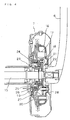
- FIG. 4 is a sectional view of the running drive device 7 provided on a crankshaft 15 of the cranks 6 rotatable by pedaling.
- the drive device 7 comprises a rotating member 16, a sprocket 18 biased by a compression coil spring 17 toward the direction of reverse rotation relative to the rotating member 16 and rotatable by the rotation of the rotating member 17 for rotating the rear wheel 11 through the chain 12, torque sensor means 19 for detecting rotational torque from the difference between the rotating member 16 and the sprocket 18 in phase and a cover member 20 so disposed as to rotate with the rotating member 16 with the sprocket 18 interposed therebetween.
- the rotating member 16 is annular and has an inner periphery defining a center hole and provided with inner teeth 21. Meshing with inner teeth 21 is a gear 22 mounted on a side end of the crankshaft 15 of the cranks 6. The crankshaft 15 rotates with the rotating member 16.
- the sprocket 18 is fastened with screws to a mount member 24 rotatably supported by a bearing 23 on the crankshaft 15, and has a peripheral toothed portion projecting radially outward beyond the rotating member 16.
- the torque sensor means 19 comprises a fixed annular member 25 secured to the mount member 24, a movable ring 26 fitting around the fixed member 25 and movable axially of the crankshaft 15 by the phase difference between the rotating member 15 and the sprocket 18, and a sensor 27 for detecting the amount of axial movement of the movable ring 26 to send a signal to the control circuit.
- the movable ring 26 can be prepared from a metal, such as aluminum or an aluminum alloy.
- the movable ring 26 is biased by a spring 28 toward the cover member 20.
- the movable ring 26 has a protrusion 29 and a cam face 30 formed on the protrusion 29.
- the fixed member 25 has a projection 31 slidable in contact with the cam face 30 of the movable ring 26.
- the protrusion 29 and the projection 31 provide a cam portion.
- the sensor 27 comprises a winding (not shown) provided around the movable ring 26 within the range of axial movement of the movable ring 26 and detects variations in the inductance of the winding due to the axial movement of the movable ring 26. The greater the amount of ingress of the ring 26 into the winding, the greater the inductance of the winding.
- the control circuit detects such variations in the inductance for controlling the motor based on the result detected.
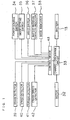
- the motor 32 housed in the hub 10 of the front wheel 9, rotates the front wheel 9 with the power supplied from the battery 13 through a charge-discharge circuit 33, or generates electricity utilizing the rotation of the front wheel 9 and charges the battery 13 through the charge-discharge circuit 33.
- the state in which the front wheel 9 is rotated with the power supplied from the battery 13 will hereinafter be referred to as the "nongenerative state,” while the state in which the battery 13 is charged with the regenerative power produced by the rotation of the front wheel 9 as the "regenerative state.
- a power source switch mounted on a manual controller provided in the vicinity of the handle 8, and at 35 a mode setting switch mounted on the manual controller for selecting one operation mode of "standard” and “autoeconomy.”
- the "standard” mode is a mode wherein no power is produced by regenerative generation
- the "autoeconomy (hereinafter referred to as 'autoeco') mode” is a mode wherein power is produced by regenerative generation.
- the manual controller has, in addition to the power source switch 34 and the mode setting switch 35, a light switch 36 for controlling the lighting of a head lamp, an indicator 37 for indicating the residual capacity of the battery 13, and a mode indicator 38 for indicating the operation mode selected by the mode setting switch 35.
- Indicated at 39 is a brake detector, which brings the motor 32 into the "regenerative state" upon detecting the application of the brake of the bicycle to charge the battery 13.
- Indicated at 40 is a speed detector for detecting the running speed of the bicycle from the speed of rotation of the motor 32.
- a torque detector 41 has the sensor 27 for detecting variations in the inductance of the winding to detect the pedaling force acting on the pedals 5.
- a crank speed detector 42 detects the number of revolutions of the cranks 6 from the output waveform of the sensor 27.
- Indicated at 43 is a control unit for receiving signals from the power source switch 34, mode setting switch 35, light switch 36, brake detector 39, speed detector 40, torque detector 41 and crank speed detector 42 to control the charge-discharge circuit 33, light for turning on or off, battery remaining capacity indicator 37 and mode indicator 38.
- the movable ring 26 which is rotatable with the rotating member 16 and movable axially of the crankshaft 15, moves into the winding of the sensor 27 with its cam face 30 brought into sliding contact with the projection 31 of the fixed member 25.
- the ingress of the movable ring 26 increases the inductance of the winding of the sensor 27.
- the torque detector 41 detects the variation in the inductance of the winding, consequently causing the control device 43 to control the drive of the motor 32 and adding the assisting power of the motor 32 to the human pedaling force for the travel of the bicycle.
- Step 1 an inquiry is made as to whether the operation mode is the "autoeco mode" (Step 1). If the inquiry is answered in the negative (namely, if the operation is in the "standard mode"), the battery is not charged by regenerative generation (Step 2).
- Step 3 an inquiry is made as to whether the cranks 6 are in rotation with up to a predetermined number of revolutions, permitting the bicycle to run at not lower than a specified speed (Step 3).
- the term the "specified speed” refers to a speed at which a sufficient amount of power can be obtained by regenerative generation. Stated more specifically, this speed is 7 km/h, and the predetermined number of revolutions of the cranks 6 is set at a value slightly lower than is needed for the cranks 6 for running on level roads at that speed.
- Step 3 When the running speed of the bicycle is found to be below the specified speed or the number of revolutions of the cranks 6 is found to be above the predetermined value in Step 3, Step 2 follows, in which no regenerative regeneration is effected.
- Step 3 recognizes that the running speed of the bicycle is at least the specified value and that the number of revolutions of the cranks 6 is up to the predetermined value, an inquiry is made as to whether power is produced by regenerative generation (Step 4).
- Step 5 follows for regenerative generation to charge the battery. If Step 4 recognizes regenerative generation, the sequence proceeds to Step 6 to check the bicycle for deceleration. If deceleration is not found in Step 6, Step 7 follows to increase the amount of power to be given by regenerative generation.
- the increase in the amount of regenerative generation of power affords an increased running distance and a greater amount of braking to thereby suppress an increase in the speed on a downward slope and assure safety and comfort of cycling.
- Step 6 If deceleration is recognized in Step 6, an inquiry is made in Step 8 as to whether the amount of power generated is at least a minimum value. When the amount is found to be less than the minimum in Step 8, Step 2 follows to discontinue regenerative generation for a further reduction in speed. If the amount is found to be not smaller than the minimum, Step 9 follows to diminish regenerative generation. Deceleration due to braking involving regenerative generation is recognized to diminish the amount of braking and thereby ensure comfortable cycling. While the brake is applied, the regenerative generation shown in the flow chart of FIG. 2 is not discontinued, with preference given to the regenerative generation by braking.
- Step 3 an inquiry is made in Step 3 as to whether the bicycle is running at the specified speed, whereas the bicycle may be checked for acceleration.
- the predetermined number of revolutions of the cranks 6 to be checked in Step 3 is set at a value slightly lower than is needed for the cranks 6 for causing the bicycle to run on a level road at the speed detected by the speed detector, whereas the predetermined value may be set at zero or a value approximate to zero.
- the instance in which the cranks 6 remain almost unrotated is an instance of braking, an instance of running on a downward slope or an instance of running higher than is needed.
- a change-over to regenerative generation is effected by detecting the cranks remaining almost unrotated (i.e., a number of revolutions below the predetermined value), whereby a simplified control mode can be realized.
Landscapes
- Engineering & Computer Science (AREA)
- Transportation (AREA)
- Mechanical Engineering (AREA)
- Power Engineering (AREA)
- Chemical & Material Sciences (AREA)
- Combustion & Propulsion (AREA)
- Life Sciences & Earth Sciences (AREA)
- Sustainable Development (AREA)
- Sustainable Energy (AREA)
- Physics & Mathematics (AREA)
- Electromagnetism (AREA)
- Electric Propulsion And Braking For Vehicles (AREA)
Applications Claiming Priority (1)
| Application Number | Priority Date | Filing Date | Title |
|---|---|---|---|
| JP2006219237A JP2008044414A (ja) | 2006-08-11 | 2006-08-11 | 電動補助自転車 |
Publications (3)
| Publication Number | Publication Date |
|---|---|
| EP1886913A2 true EP1886913A2 (de) | 2008-02-13 |
| EP1886913A3 EP1886913A3 (de) | 2010-02-17 |
| EP1886913B1 EP1886913B1 (de) | 2011-10-19 |
Family
ID=38814598
Family Applications (1)
| Application Number | Title | Priority Date | Filing Date |
|---|---|---|---|
| EP07012351A Not-in-force EP1886913B1 (de) | 2006-08-11 | 2007-06-25 | Elektrisch unterstütztes Fahrrad |
Country Status (4)
| Country | Link |
|---|---|
| EP (1) | EP1886913B1 (de) |
| JP (1) | JP2008044414A (de) |
| CN (1) | CN101121434A (de) |
| AT (1) | ATE529324T1 (de) |
Cited By (15)
| Publication number | Priority date | Publication date | Assignee | Title |
|---|---|---|---|---|
| ES2358714A1 (es) * | 2009-05-22 | 2011-05-13 | Universitat Politècnica De Catalunya | Bicicleta eléctrica con capacidad para recuperar energía en bajadas y frenadas. |
| NL2006711A (nl) * | 2010-05-06 | 2011-11-08 | Bosch Gmbh Robert | Werkwijze en besturingsinrichting voor het bedienen van een elektrische rem en het mogelijk maken van een terugtraprem van een elektrofiets. |
| EP2394902A1 (de) * | 2010-06-11 | 2011-12-14 | Shimano Inc. | Fahrrad mit Hilfsmotor und Steuervorrichtung |
| US20110304200A1 (en) * | 2010-06-11 | 2011-12-15 | Taiyo Yuden Co., Ltd. | Auxiliary bicycle power supply system |
| WO2012104810A1 (en) | 2011-02-03 | 2012-08-09 | Politecnico Di Milano | Electrically pedal-assisted bicycle |
| CN103072493A (zh) * | 2011-10-26 | 2013-05-01 | 华创车电技术中心股份有限公司 | 下坡定速电力回充系统 |
| EP2631165A1 (de) * | 2012-02-27 | 2013-08-28 | Honda Motor Co., Ltd. | Stromunterstütztes Fahrrad |
| WO2014067710A1 (de) * | 2012-10-31 | 2014-05-08 | Robert Bosch Gmbh | Fahrrad mit elektrischem hilfsantrieb und schaltvorgangserkennung |
| US8725340B1 (en) | 2012-10-29 | 2014-05-13 | Taiyo Yuden Co., Ltd. | Motor drive controller and electric power-assisted vehicle |
| US9108700B2 (en) | 2013-05-13 | 2015-08-18 | Darfon Electronics (Suzhou) Co., Ltd. | Method for automatic adjustment of pedelec |
| US9136780B2 (en) | 2012-09-24 | 2015-09-15 | Taiyo Yuden Co., Ltd. | Controller for driving a motor and electric power-assisted vehicle |
| EP3064422A1 (de) * | 2015-03-05 | 2016-09-07 | Robert Bosch Gmbh | Antrieb für ein pedalgetriebenes fahrzeug |
| EP3009295A4 (de) * | 2013-06-14 | 2017-07-05 | Microspace Corporation | Motorantriebssteuerungsvorrichtung |
| US10137787B2 (en) | 2015-11-09 | 2018-11-27 | Taiyo Yuden Co., Ltd. | Regenerative controller for electric motor, regenerative driver for electric motor, and power-assisted vehicle |
| EP2983975B1 (de) | 2013-04-08 | 2019-01-02 | Robert Bosch GmbH | Pedalgetriebenes fahrzeug sowie verfahren zum betreiben des pedalgetriebenen fahrzeugs |
Families Citing this family (13)
| Publication number | Priority date | Publication date | Assignee | Title |
|---|---|---|---|---|
| JP5114244B2 (ja) | 2008-02-26 | 2013-01-09 | オリンパス株式会社 | クロック再生回路 |
| JP5463071B2 (ja) * | 2009-05-12 | 2014-04-09 | 太陽誘電株式会社 | 踏力検出装置を備えた電動車 |
| EP2671788B1 (de) * | 2011-01-31 | 2016-04-20 | Sanyo Electric Co., Ltd. | Elektrisches fahrrad |
| JP2013121797A (ja) * | 2011-12-12 | 2013-06-20 | Honda Motor Co Ltd | 電動補助自転車 |
| JP5604562B1 (ja) * | 2013-05-27 | 2014-10-08 | ブリヂストンサイクル株式会社 | 電動機付自転車 |
| JP6199089B2 (ja) * | 2013-06-20 | 2017-09-20 | ブリヂストンサイクル株式会社 | 電動アシスト自転車 |
| GB2537201B (en) | 2014-12-17 | 2019-09-04 | Williams Advanced Engineering Ltd | An electric drive wheel hub system for a vehicle and a vehicle incorporating the same |
| JP6381573B2 (ja) * | 2015-11-09 | 2018-08-29 | 太陽誘電株式会社 | 電動機の回生制御装置、電動機の回生駆動装置、及び電動補助車両 |
| CN110077517A (zh) * | 2018-01-26 | 2019-08-02 | 上海腾通信息科技有限公司 | 一种混合动力电助力车及其控制方法 |
| CN112758239A (zh) * | 2021-01-25 | 2021-05-07 | 深圳市达伦仕科技有限公司 | 智能电动助力轮 |
| CN113415373B (zh) * | 2021-07-09 | 2022-09-27 | 广东高标电子科技有限公司 | 助力车能量回收方法、装置、电子设备及存储介质 |
| IT202200005615A1 (it) * | 2022-03-22 | 2023-09-22 | Oli Ebike Systems S R L | Sistema per il controllo di un motore elettrico di una bicicletta a pedalata assistita |
| KR102831076B1 (ko) * | 2023-11-17 | 2025-07-08 | 주식회사 서브루나바이크 | 패드의 위치 조절이 용이한 림브레이크를 갖는 하이브리드 전기자전거 |
Citations (5)
| Publication number | Priority date | Publication date | Assignee | Title |
|---|---|---|---|---|
| US3921745A (en) | 1973-07-23 | 1975-11-25 | Mcculloch Corp | Electric bicycle |
| JPH04100790A (ja) | 1990-08-16 | 1992-04-02 | Yamaha Motor Co Ltd | 電動モータ付き人力駆動装置 |
| FR2727376A1 (fr) | 1994-11-25 | 1996-05-31 | Seb Sa | Derailleur electronique |
| EP0798204A1 (de) | 1996-03-29 | 1997-10-01 | Honda Giken Kogyo Kabushiki Kaisha | Regenerierungs-Steuereinrichtung für Fahrrad mit Hilfsmotor |
| WO2006029514A1 (en) | 2004-09-14 | 2006-03-23 | 9141-7030 Québec Inc. | Energy management system for motor-assisted user-propelled vehicles |
Family Cites Families (2)
| Publication number | Priority date | Publication date | Assignee | Title |
|---|---|---|---|---|
| JPH08140212A (ja) * | 1994-11-09 | 1996-05-31 | Yamaha Motor Co Ltd | 回生制御装置 |
| JPH1081290A (ja) * | 1996-09-11 | 1998-03-31 | Aichi Steel Works Ltd | トルク補助式電動自転車 |
-
2006
- 2006-08-11 JP JP2006219237A patent/JP2008044414A/ja active Pending
-
2007
- 2007-06-25 EP EP07012351A patent/EP1886913B1/de not_active Not-in-force
- 2007-06-25 AT AT07012351T patent/ATE529324T1/de not_active IP Right Cessation
- 2007-08-13 CN CNA2007101410130A patent/CN101121434A/zh active Pending
Patent Citations (5)
| Publication number | Priority date | Publication date | Assignee | Title |
|---|---|---|---|---|
| US3921745A (en) | 1973-07-23 | 1975-11-25 | Mcculloch Corp | Electric bicycle |
| JPH04100790A (ja) | 1990-08-16 | 1992-04-02 | Yamaha Motor Co Ltd | 電動モータ付き人力駆動装置 |
| FR2727376A1 (fr) | 1994-11-25 | 1996-05-31 | Seb Sa | Derailleur electronique |
| EP0798204A1 (de) | 1996-03-29 | 1997-10-01 | Honda Giken Kogyo Kabushiki Kaisha | Regenerierungs-Steuereinrichtung für Fahrrad mit Hilfsmotor |
| WO2006029514A1 (en) | 2004-09-14 | 2006-03-23 | 9141-7030 Québec Inc. | Energy management system for motor-assisted user-propelled vehicles |
Cited By (26)
| Publication number | Priority date | Publication date | Assignee | Title |
|---|---|---|---|---|
| ES2358714A1 (es) * | 2009-05-22 | 2011-05-13 | Universitat Politècnica De Catalunya | Bicicleta eléctrica con capacidad para recuperar energía en bajadas y frenadas. |
| DE102010028645B4 (de) | 2010-05-06 | 2022-01-20 | Robert Bosch Gmbh | Verfahren und Steuerungsvorrichtung zur Betätigung einer elektrischen Bremse eines Elektrofahrrads, Energieversorgungsvorrichtung mit der Steuerungsvorrichtung und elektrischer Antriebsstrang zum Antrieb eines Elektrofahrrads |
| NL2006711A (nl) * | 2010-05-06 | 2011-11-08 | Bosch Gmbh Robert | Werkwijze en besturingsinrichting voor het bedienen van een elektrische rem en het mogelijk maken van een terugtraprem van een elektrofiets. |
| BE1020317A5 (fr) * | 2010-05-06 | 2013-08-06 | Bosch Gmbh Robert | Procede et dispositif de commande d'un frein electrique de velo electrique. |
| EP2394902A1 (de) * | 2010-06-11 | 2011-12-14 | Shimano Inc. | Fahrrad mit Hilfsmotor und Steuervorrichtung |
| US20110304200A1 (en) * | 2010-06-11 | 2011-12-15 | Taiyo Yuden Co., Ltd. | Auxiliary bicycle power supply system |
| US9308964B2 (en) | 2010-06-11 | 2016-04-12 | Shimano Inc. | Bicycle motor control system |
| US20120316709A1 (en) * | 2010-06-11 | 2012-12-13 | Shimano Inc. | Bicycle motor control system |
| US8981588B2 (en) * | 2010-06-11 | 2015-03-17 | Shimano Inc. | Auxiliary bicycle power supply system |
| WO2012104810A1 (en) | 2011-02-03 | 2012-08-09 | Politecnico Di Milano | Electrically pedal-assisted bicycle |
| US20140062351A1 (en) * | 2011-02-03 | 2014-03-06 | Politecnico Di Milano | Electrically Pedal-Assisted Bicycle |
| US9102317B2 (en) * | 2011-02-03 | 2015-08-11 | Politecnico Di Milano | Electrically pedal-assisted bicycle |
| CN103072493A (zh) * | 2011-10-26 | 2013-05-01 | 华创车电技术中心股份有限公司 | 下坡定速电力回充系统 |
| CN103287543A (zh) * | 2012-02-27 | 2013-09-11 | 本田技研工业株式会社 | 电动辅助自行车 |
| EP2631165A1 (de) * | 2012-02-27 | 2013-08-28 | Honda Motor Co., Ltd. | Stromunterstütztes Fahrrad |
| US9136780B2 (en) | 2012-09-24 | 2015-09-15 | Taiyo Yuden Co., Ltd. | Controller for driving a motor and electric power-assisted vehicle |
| US8725340B1 (en) | 2012-10-29 | 2014-05-13 | Taiyo Yuden Co., Ltd. | Motor drive controller and electric power-assisted vehicle |
| WO2014067710A1 (de) * | 2012-10-31 | 2014-05-08 | Robert Bosch Gmbh | Fahrrad mit elektrischem hilfsantrieb und schaltvorgangserkennung |
| EP2983975B1 (de) | 2013-04-08 | 2019-01-02 | Robert Bosch GmbH | Pedalgetriebenes fahrzeug sowie verfahren zum betreiben des pedalgetriebenen fahrzeugs |
| EP2983975B2 (de) † | 2013-04-08 | 2022-07-20 | Robert Bosch GmbH | Pedalgetriebenes fahrzeug sowie verfahren zum betreiben des pedalgetriebenen fahrzeugs |
| US9108700B2 (en) | 2013-05-13 | 2015-08-18 | Darfon Electronics (Suzhou) Co., Ltd. | Method for automatic adjustment of pedelec |
| EP3009295A4 (de) * | 2013-06-14 | 2017-07-05 | Microspace Corporation | Motorantriebssteuerungsvorrichtung |
| US9896153B2 (en) | 2013-06-14 | 2018-02-20 | Microspace Corporation | Motor driving control apparatus |
| US10040508B2 (en) | 2013-06-14 | 2018-08-07 | Microspace Corporation | Motor driving control apparatus |
| EP3064422A1 (de) * | 2015-03-05 | 2016-09-07 | Robert Bosch Gmbh | Antrieb für ein pedalgetriebenes fahrzeug |
| US10137787B2 (en) | 2015-11-09 | 2018-11-27 | Taiyo Yuden Co., Ltd. | Regenerative controller for electric motor, regenerative driver for electric motor, and power-assisted vehicle |
Also Published As
| Publication number | Publication date |
|---|---|
| CN101121434A (zh) | 2008-02-13 |
| JP2008044414A (ja) | 2008-02-28 |
| ATE529324T1 (de) | 2011-11-15 |
| EP1886913B1 (de) | 2011-10-19 |
| EP1886913A3 (de) | 2010-02-17 |
Similar Documents
| Publication | Publication Date | Title |
|---|---|---|
| EP1886913B1 (de) | Elektrisch unterstütztes Fahrrad | |
| EP1236640B1 (de) | Steuerungseinrichtung für Fahrrad mit Hilfsmotor | |
| JP3642364B2 (ja) | 補助動力付き自転車の回生制御装置 | |
| JP5211181B2 (ja) | 電動補助自転車 | |
| JP4906982B1 (ja) | 電動自転車 | |
| CN102442397B (zh) | 电动助力自行车的控制装置 | |
| CN103038128B (zh) | 电动自行车 | |
| CN102442396B (zh) | 电动助力自行车的控制装置 | |
| JP5842105B2 (ja) | 電動アシスト自転車 | |
| CA2511260C (en) | Electrically assisted bicycle | |
| CN102442398B (zh) | 电动助力自行车的控制装置 | |
| JP6669422B1 (ja) | 自己充電で走行可能な電動自転車 | |
| JP2012076578A (ja) | 電動補助自転車の制御装置 | |
| CN111017103A (zh) | 助力自行车 | |
| JP2003104274A (ja) | 電動補助自転車 | |
| JPH04358988A (ja) | 電動モータ付き自転車 | |
| US11858292B2 (en) | Hub assembly for human-powered vehicle | |
| KR101473183B1 (ko) | 전기 자전거 | |
| JP3985930B2 (ja) | 電動補助自転車の補助力制御装置 | |
| JP2008044565A (ja) | 電動車及び電動補助自転車 | |
| EP3354551A1 (de) | Fahrrad mit motorbremse | |
| CN113320636A (zh) | 人力驱动车用控制装置 | |
| JP2002255082A (ja) | 電動補助自転車の制御装置 | |
| US11643159B2 (en) | Electric power generator for human-powered vehicle | |
| JP2014113023A (ja) | 電動車用駆動装置、及び電動車 |
Legal Events
| Date | Code | Title | Description |
|---|---|---|---|
| PUAI | Public reference made under article 153(3) epc to a published international application that has entered the european phase |
Free format text: ORIGINAL CODE: 0009012 |
|
| AK | Designated contracting states |
Kind code of ref document: A2 Designated state(s): AT BE BG CH CY CZ DE DK EE ES FI FR GB GR HU IE IS IT LI LT LU LV MC MT NL PL PT RO SE SI SK TR |
|
| AX | Request for extension of the european patent |
Extension state: AL BA HR MK YU |
|
| PUAL | Search report despatched |
Free format text: ORIGINAL CODE: 0009013 |
|
| AK | Designated contracting states |
Kind code of ref document: A3 Designated state(s): AT BE BG CH CY CZ DE DK EE ES FI FR GB GR HU IE IS IT LI LT LU LV MC MT NL PL PT RO SE SI SK TR |
|
| AX | Request for extension of the european patent |
Extension state: AL BA HR MK RS |
|
| 17P | Request for examination filed |
Effective date: 20100813 |
|
| 17Q | First examination report despatched |
Effective date: 20100916 |
|
| AKX | Designation fees paid |
Designated state(s): AT BE BG CH CY CZ DE DK EE ES FI FR GB GR HU IE IS IT LI LT LU LV MC MT NL PL PT RO SE SI SK TR |
|
| GRAP | Despatch of communication of intention to grant a patent |
Free format text: ORIGINAL CODE: EPIDOSNIGR1 |
|
| RIC1 | Information provided on ipc code assigned before grant |
Ipc: B62M 23/02 20100101AFI20110325BHEP |
|
| GRAS | Grant fee paid |
Free format text: ORIGINAL CODE: EPIDOSNIGR3 |
|
| GRAA | (expected) grant |
Free format text: ORIGINAL CODE: 0009210 |
|
| AK | Designated contracting states |
Kind code of ref document: B1 Designated state(s): AT BE BG CH CY CZ DE DK EE ES FI FR GB GR HU IE IS IT LI LT LU LV MC MT NL PL PT RO SE SI SK TR |
|
| REG | Reference to a national code |
Ref country code: GB Ref legal event code: FG4D |
|
| REG | Reference to a national code |
Ref country code: CH Ref legal event code: EP |
|
| REG | Reference to a national code |
Ref country code: IE Ref legal event code: FG4D |
|
| REG | Reference to a national code |
Ref country code: NL Ref legal event code: T3 |
|
| REG | Reference to a national code |
Ref country code: DE Ref legal event code: R096 Ref document number: 602007017928 Country of ref document: DE Effective date: 20120112 |
|
| LTIE | Lt: invalidation of european patent or patent extension |
Effective date: 20111019 |
|
| REG | Reference to a national code |
Ref country code: AT Ref legal event code: MK05 Ref document number: 529324 Country of ref document: AT Kind code of ref document: T Effective date: 20111019 |
|
| PG25 | Lapsed in a contracting state [announced via postgrant information from national office to epo] |
Ref country code: IS Free format text: LAPSE BECAUSE OF FAILURE TO SUBMIT A TRANSLATION OF THE DESCRIPTION OR TO PAY THE FEE WITHIN THE PRESCRIBED TIME-LIMIT Effective date: 20120219 Ref country code: LT Free format text: LAPSE BECAUSE OF FAILURE TO SUBMIT A TRANSLATION OF THE DESCRIPTION OR TO PAY THE FEE WITHIN THE PRESCRIBED TIME-LIMIT Effective date: 20111019 |
|
| PG25 | Lapsed in a contracting state [announced via postgrant information from national office to epo] |
Ref country code: LV Free format text: LAPSE BECAUSE OF FAILURE TO SUBMIT A TRANSLATION OF THE DESCRIPTION OR TO PAY THE FEE WITHIN THE PRESCRIBED TIME-LIMIT Effective date: 20111019 Ref country code: PT Free format text: LAPSE BECAUSE OF FAILURE TO SUBMIT A TRANSLATION OF THE DESCRIPTION OR TO PAY THE FEE WITHIN THE PRESCRIBED TIME-LIMIT Effective date: 20120220 Ref country code: SI Free format text: LAPSE BECAUSE OF FAILURE TO SUBMIT A TRANSLATION OF THE DESCRIPTION OR TO PAY THE FEE WITHIN THE PRESCRIBED TIME-LIMIT Effective date: 20111019 Ref country code: GR Free format text: LAPSE BECAUSE OF FAILURE TO SUBMIT A TRANSLATION OF THE DESCRIPTION OR TO PAY THE FEE WITHIN THE PRESCRIBED TIME-LIMIT Effective date: 20120120 Ref country code: SE Free format text: LAPSE BECAUSE OF FAILURE TO SUBMIT A TRANSLATION OF THE DESCRIPTION OR TO PAY THE FEE WITHIN THE PRESCRIBED TIME-LIMIT Effective date: 20111019 |
|
| PG25 | Lapsed in a contracting state [announced via postgrant information from national office to epo] |
Ref country code: CY Free format text: LAPSE BECAUSE OF FAILURE TO SUBMIT A TRANSLATION OF THE DESCRIPTION OR TO PAY THE FEE WITHIN THE PRESCRIBED TIME-LIMIT Effective date: 20111019 |
|
| PG25 | Lapsed in a contracting state [announced via postgrant information from national office to epo] |
Ref country code: SK Free format text: LAPSE BECAUSE OF FAILURE TO SUBMIT A TRANSLATION OF THE DESCRIPTION OR TO PAY THE FEE WITHIN THE PRESCRIBED TIME-LIMIT Effective date: 20111019 Ref country code: DK Free format text: LAPSE BECAUSE OF FAILURE TO SUBMIT A TRANSLATION OF THE DESCRIPTION OR TO PAY THE FEE WITHIN THE PRESCRIBED TIME-LIMIT Effective date: 20111019 Ref country code: BG Free format text: LAPSE BECAUSE OF FAILURE TO SUBMIT A TRANSLATION OF THE DESCRIPTION OR TO PAY THE FEE WITHIN THE PRESCRIBED TIME-LIMIT Effective date: 20120119 Ref country code: EE Free format text: LAPSE BECAUSE OF FAILURE TO SUBMIT A TRANSLATION OF THE DESCRIPTION OR TO PAY THE FEE WITHIN THE PRESCRIBED TIME-LIMIT Effective date: 20111019 Ref country code: CZ Free format text: LAPSE BECAUSE OF FAILURE TO SUBMIT A TRANSLATION OF THE DESCRIPTION OR TO PAY THE FEE WITHIN THE PRESCRIBED TIME-LIMIT Effective date: 20111019 |
|
| PLBE | No opposition filed within time limit |
Free format text: ORIGINAL CODE: 0009261 |
|
| STAA | Information on the status of an ep patent application or granted ep patent |
Free format text: STATUS: NO OPPOSITION FILED WITHIN TIME LIMIT |
|
| PG25 | Lapsed in a contracting state [announced via postgrant information from national office to epo] |
Ref country code: PL Free format text: LAPSE BECAUSE OF FAILURE TO SUBMIT A TRANSLATION OF THE DESCRIPTION OR TO PAY THE FEE WITHIN THE PRESCRIBED TIME-LIMIT Effective date: 20111019 Ref country code: IT Free format text: LAPSE BECAUSE OF FAILURE TO SUBMIT A TRANSLATION OF THE DESCRIPTION OR TO PAY THE FEE WITHIN THE PRESCRIBED TIME-LIMIT Effective date: 20111019 Ref country code: RO Free format text: LAPSE BECAUSE OF FAILURE TO SUBMIT A TRANSLATION OF THE DESCRIPTION OR TO PAY THE FEE WITHIN THE PRESCRIBED TIME-LIMIT Effective date: 20111019 |
|
| 26N | No opposition filed |
Effective date: 20120720 |
|
| REG | Reference to a national code |
Ref country code: DE Ref legal event code: R097 Ref document number: 602007017928 Country of ref document: DE Effective date: 20120720 |
|
| BERE | Be: lapsed |
Owner name: SANYO ELECTRIC CO., LTD. Effective date: 20120630 |
|
| PG25 | Lapsed in a contracting state [announced via postgrant information from national office to epo] |
Ref country code: MC Free format text: LAPSE BECAUSE OF NON-PAYMENT OF DUE FEES Effective date: 20120630 Ref country code: AT Free format text: LAPSE BECAUSE OF FAILURE TO SUBMIT A TRANSLATION OF THE DESCRIPTION OR TO PAY THE FEE WITHIN THE PRESCRIBED TIME-LIMIT Effective date: 20111019 |
|
| REG | Reference to a national code |
Ref country code: CH Ref legal event code: PL |
|
| REG | Reference to a national code |
Ref country code: CH Ref legal event code: PL |
|
| GBPC | Gb: european patent ceased through non-payment of renewal fee |
Effective date: 20120625 |
|
| REG | Reference to a national code |
Ref country code: IE Ref legal event code: MM4A |
|
| PG25 | Lapsed in a contracting state [announced via postgrant information from national office to epo] |
Ref country code: GB Free format text: LAPSE BECAUSE OF NON-PAYMENT OF DUE FEES Effective date: 20120625 Ref country code: BE Free format text: LAPSE BECAUSE OF NON-PAYMENT OF DUE FEES Effective date: 20120630 Ref country code: ES Free format text: LAPSE BECAUSE OF FAILURE TO SUBMIT A TRANSLATION OF THE DESCRIPTION OR TO PAY THE FEE WITHIN THE PRESCRIBED TIME-LIMIT Effective date: 20120130 Ref country code: IE Free format text: LAPSE BECAUSE OF NON-PAYMENT OF DUE FEES Effective date: 20120625 Ref country code: CH Free format text: LAPSE BECAUSE OF NON-PAYMENT OF DUE FEES Effective date: 20120630 Ref country code: LI Free format text: LAPSE BECAUSE OF NON-PAYMENT OF DUE FEES Effective date: 20120630 |
|
| PG25 | Lapsed in a contracting state [announced via postgrant information from national office to epo] |
Ref country code: FI Free format text: LAPSE BECAUSE OF FAILURE TO SUBMIT A TRANSLATION OF THE DESCRIPTION OR TO PAY THE FEE WITHIN THE PRESCRIBED TIME-LIMIT Effective date: 20111019 |
|
| PG25 | Lapsed in a contracting state [announced via postgrant information from national office to epo] |
Ref country code: MT Free format text: LAPSE BECAUSE OF FAILURE TO SUBMIT A TRANSLATION OF THE DESCRIPTION OR TO PAY THE FEE WITHIN THE PRESCRIBED TIME-LIMIT Effective date: 20111019 |
|
| PG25 | Lapsed in a contracting state [announced via postgrant information from national office to epo] |
Ref country code: TR Free format text: LAPSE BECAUSE OF FAILURE TO SUBMIT A TRANSLATION OF THE DESCRIPTION OR TO PAY THE FEE WITHIN THE PRESCRIBED TIME-LIMIT Effective date: 20111019 |
|
| PG25 | Lapsed in a contracting state [announced via postgrant information from national office to epo] |
Ref country code: LU Free format text: LAPSE BECAUSE OF NON-PAYMENT OF DUE FEES Effective date: 20120625 |
|
| PG25 | Lapsed in a contracting state [announced via postgrant information from national office to epo] |
Ref country code: HU Free format text: LAPSE BECAUSE OF FAILURE TO SUBMIT A TRANSLATION OF THE DESCRIPTION OR TO PAY THE FEE WITHIN THE PRESCRIBED TIME-LIMIT Effective date: 20070625 |
|
| REG | Reference to a national code |
Ref country code: FR Ref legal event code: PLFP Year of fee payment: 9 |
|
| PGFP | Annual fee paid to national office [announced via postgrant information from national office to epo] |
Ref country code: NL Payment date: 20150510 Year of fee payment: 9 Ref country code: FR Payment date: 20150608 Year of fee payment: 9 |
|
| REG | Reference to a national code |
Ref country code: NL Ref legal event code: MM Effective date: 20160701 |
|
| REG | Reference to a national code |
Ref country code: FR Ref legal event code: ST Effective date: 20170228 |
|
| PG25 | Lapsed in a contracting state [announced via postgrant information from national office to epo] |
Ref country code: FR Free format text: LAPSE BECAUSE OF NON-PAYMENT OF DUE FEES Effective date: 20160630 |
|
| PG25 | Lapsed in a contracting state [announced via postgrant information from national office to epo] |
Ref country code: NL Free format text: LAPSE BECAUSE OF NON-PAYMENT OF DUE FEES Effective date: 20160701 |
|
| PGFP | Annual fee paid to national office [announced via postgrant information from national office to epo] |
Ref country code: DE Payment date: 20240328 Year of fee payment: 18 |
|
| REG | Reference to a national code |
Ref country code: DE Ref legal event code: R119 Ref document number: 602007017928 Country of ref document: DE |
|
| PG25 | Lapsed in a contracting state [announced via postgrant information from national office to epo] |
Ref country code: DE Free format text: LAPSE BECAUSE OF NON-PAYMENT OF DUE FEES Effective date: 20260101 |