EP1887149A2 - Circuit hydraulique pour engin de chantier - Google Patents
Circuit hydraulique pour engin de chantier Download PDFInfo
- Publication number
- EP1887149A2 EP1887149A2 EP07015151A EP07015151A EP1887149A2 EP 1887149 A2 EP1887149 A2 EP 1887149A2 EP 07015151 A EP07015151 A EP 07015151A EP 07015151 A EP07015151 A EP 07015151A EP 1887149 A2 EP1887149 A2 EP 1887149A2
- Authority
- EP
- European Patent Office
- Prior art keywords
- pressure
- shifted
- hydraulic
- switching valve
- signal line
- Prior art date
- Legal status (The legal status is an assumption and is not a legal conclusion. Google has not performed a legal analysis and makes no representation as to the accuracy of the status listed.)
- Withdrawn
Links
- 238000010276 construction Methods 0.000 title claims abstract description 27
- 239000012530 fluid Substances 0.000 claims description 49
- 238000010586 diagram Methods 0.000 description 6
- 239000000470 constituent Substances 0.000 description 2
- 238000007792 addition Methods 0.000 description 1
- 238000004519 manufacturing process Methods 0.000 description 1
- 230000004048 modification Effects 0.000 description 1
- 238000012986 modification Methods 0.000 description 1
- 230000007935 neutral effect Effects 0.000 description 1
- 238000006467 substitution reaction Methods 0.000 description 1
Images


Classifications
-
- F—MECHANICAL ENGINEERING; LIGHTING; HEATING; WEAPONS; BLASTING
- F15—FLUID-PRESSURE ACTUATORS; HYDRAULICS OR PNEUMATICS IN GENERAL
- F15B—SYSTEMS ACTING BY MEANS OF FLUIDS IN GENERAL; FLUID-PRESSURE ACTUATORS, e.g. SERVOMOTORS; DETAILS OF FLUID-PRESSURE SYSTEMS, NOT OTHERWISE PROVIDED FOR
- F15B11/00—Servomotor systems without provision for follow-up action; Circuits therefor
-
- E—FIXED CONSTRUCTIONS
- E02—HYDRAULIC ENGINEERING; FOUNDATIONS; SOIL SHIFTING
- E02F—DREDGING; SOIL-SHIFTING
- E02F9/00—Component parts of dredgers or soil-shifting machines, not restricted to one of the kinds covered by groups E02F3/00 - E02F7/00
- E02F9/20—Drives; Control devices
- E02F9/22—Hydraulic or pneumatic drives
- E02F9/2221—Control of flow rate; Load sensing arrangements
- E02F9/2239—Control of flow rate; Load sensing arrangements using two or more pumps with cross-assistance
-
- E—FIXED CONSTRUCTIONS
- E02—HYDRAULIC ENGINEERING; FOUNDATIONS; SOIL SHIFTING
- E02F—DREDGING; SOIL-SHIFTING
- E02F9/00—Component parts of dredgers or soil-shifting machines, not restricted to one of the kinds covered by groups E02F3/00 - E02F7/00
- E02F9/20—Drives; Control devices
- E02F9/22—Hydraulic or pneumatic drives
- E02F9/2278—Hydraulic circuits
- E02F9/2292—Systems with two or more pumps
Definitions
- the present invention relates to a hydraulic circuit for a construction machine, which can implement an auto idle function by automatically reducing revolution of an engine when a working device of the construction machine is not driven.
- the present invention relates to a hydraulic circuit for a construction machine, which can minimize an energy loss of a hydraulic system by automatically reducing revolution of an engine when a working device such as a boom is not driven.
- pilot signal lines related to an auto idle function When corresponding switching valves are switched, the pilot signal lines are intercepted. The switching state of the valves and the connected lines between a main pump and a working device during the switching operation of the corresponding switching valves are not separately illustrated.
- a conventional hydraulic circuit for a construction machine having an auto idle function includes first, second, and third hydraulic pumps P1, P2, and P3; a first switching valve A composed of valves installed in a flow path of the first hydraulic pump P1 and shifted to control hydraulic fluid fed to working devices (right traveling motor, arm, boom, bucket, and so forth); a second switching valve B composed of valves installed in a flow path of the second hydraulic pump P2 and shifted to control hydraulic fluid fed to working devices (left traveling motor, arm, option device, and so forth); a third switching valve C composed of valves installed in a flow path of the third hydraulic pump P3 and shifted to control hydraulic fluid fed to a swing device and so on; and a confluence switching valve 8 installed on a downstream side of the flow path of the third hydraulic pump P3 and shifted to selectively supply the hydraulic fluid from the third hydraulic pump P3 to the working devices on the first hydraulic pump side P1 or the working devices on the second hydraulic pump side P2, in response to a pilot signal pressure Pi1 applied thereto
- the hydraulic fluid fed from the first hydraulic pump P1 is supplied to the right traveling motor and the hydraulic fluid fed from the second hydraulic pump P2 is supplied to the left traveling motor to drive the traveling motors.
- the confluence switching valve 8 is used to supply the hydraulic fluid fed from the third hydraulic pump P3 to the working devices.
- the confluence switching valve 8 is shifted, in response to the pilot signal pressure Pi1 applied thereto, to supply the hydraulic fluid fed from the third hydraulic pump P3 to the working devices (arm, boom, bucket, and so forth) on the first hydraulic pump side P1 or to the working devices (arm, boom, option device, and so forth) on the second hydraulic pump side P2.
- the pilot signal pressure Pi1 for shifting the confluence switching valve 8 is supplied from a pilot pump (not illustrated) through a first throttling part 1 installed in a pilot signal line 3.
- a signal line 4 includes a signal line 5 passing through the switching valves A and B for the working devices and a signal line 6 passing through a switching valve D for traveling devices. In the case where only either the working devices or the traveling devices are shifted to operate, no signal pressure is formed in the pilot signal line 3.
- the pilot signal pressure Pi1 is formed in the pilot signal line 3
- the confluence switching valve 8 is shifted in response to the pilot signal pressure Pi1 formed in the pilot signal line 3. Accordingly, the hydraulic fluid fed from the third hydraulic pump P3 is supplied to the working devices (arm, bucket, boom, and so forth) of the first hydraulic pump side P1 or the working devices (arm, boom, option device, and so forth) of the second hydraulic pump side P2.
- the signal line 7 is connected to the signal line for supplying the pilot signal pressure to the confluence switching valve 8 and is connected to a flow path in which a second throttling part 2 is installed.
- the signal line 7 is constructed to pass through all the switching valves A, B, C, and D for the working devices and the traveling devices.
- another conventional hydraulic circuit for a construction machine having an auto idle function includes a confluence switching valve 8 that is shifted by a pilot signal pressure Pi1 fed through a third throttling part 11 formed in a pilot signal line 13; a signal line 15 which is connected to the pilot signal line 13 and in which a signal pressure is formed when switching valves A and B for working devices are shifted; a signal line 16 which is connected to the pilot signal line 13 and in which a signal pressure is formed when a switching valve D for working devices is shifted; and a signal line 17 which is connected to a pilot signal pressure Pi2 formed through a fourth throttling part 12 and in which a signal pressure is formed when the switching valves A, B, C, and D for the working devices and the traveling devices connected to first to third hydraulic pumps P1, P2, and P3, respectively, are shifted.
- the conventional hydraulic circuit of FIG. 2 further includes the first, second, and third hydraulic pumps P1, P2, and P3; the first switching valve A composed of valves installed in a flow path of the first hydraulic pump P1 and shifted to control hydraulic fluid fed to working devices (right traveling motor, arm, and so forth); the second switching valve B composed of valves installed in a flow path of the second hydraulic pump P2 and shifted to control hydraulic fluid fed to working devices (left traveling motor, boom, and so forth); and the third switching valve C composed of valves installed in a flow path of the third hydraulic pump P3 and shifted to control hydraulic fluid fed to a swing device and so on.
- the first switching valve A composed of valves installed in a flow path of the first hydraulic pump P1 and shifted to control hydraulic fluid fed to working devices (right traveling motor, arm, and so forth)
- the second switching valve B composed of valves installed in a flow path of the second hydraulic pump P2 and shifted to control hydraulic fluid fed to working devices (left traveling motor, boom, and so forth)
- the third switching valve C
- the conventional hydraulic circuits having an auto idle function requires a confluence circuit and separate auto idle signal lines, and this causes the construction of the signal lines to be complicated.
- the hydraulic circuit as illustrated in FIG. 2 has a very complicated signal lines.
- the hydraulic fluid may leak through joint surfaces of the respective switching valves A, B, C, and D.
- the formed auto-idle pressure may become unstable due to the leakage of the hydraulic fluid.
- the present invention has been made to solve the above-mentioned problems occurring in the prior art while advantages achieved by the prior art are maintained intact.
- One object of the present invention is to provide a hydraulic circuit for a construction machine, which can simplify the construction of signal lines in a hydraulic circuit having a confluence circuit and auto idle signal lines.
- the hydraulic circuit for a construction machine can stably maintain the formed auto-idle pressure by minimizing the leakage of hydraulic fluid through joint surfaces of switching valves for working devices and traveling devices.
- a hydraulic circuit for a construction machine which includes first, second, and third hydraulic pumps; a first switching valve composed of valves installed in a flow path of the first hydraulic pump and shifted to control hydraulic fluid fed to a right traveling device and working devices; a second switching valve composed of valves installed in a flow path of the second hydraulic pump and shifted to control hydraulic fluid fed to a left traveling device and working devices; a third switching valve composed of valves installed in a flow path of the third hydraulic pump and shifted to control hydraulic fluid fed to working devices; a confluence switching valve installed on a downstream side of the flow path of the third hydraulic pump and shifted to selectively supply the hydraulic fluid from the third hydraulic pump to the working devices on the first hydraulic pump side or the working devices on the second hydraulic pump side; a first shuttle valve selecting any one of a pressure of a first signal line in which a signal pressure is formed when the third switching valve for the working devices connected to the third hydraulic pump is shifted and a pressure of
- the hydraulic circuit according to one aspect of the present invention further includes a valve having an inlet that is connected to a flow path connecting the second shuttle valve and the third signal line and an outlet that is connected to a pilot signal line for supplying a pilot signal pressure to the confluence switching valve.
- a hydraulic circuit for a construction machine which includes first, second, and third hydraulic pumps; a first switching valve composed of valves installed in a flow path of the first hydraulic pump and shifted to control hydraulic fluid fed to a right traveling device and working devices; a second switching valve composed of valves installed in a flow path of the second hydraulic pump and shifted to control hydraulic fluid fed to a left traveling device and working devices; a third switching valve composed of valves installed in a flow path of the third hydraulic pump and shifted to control hydraulic fluid fed to working devices; a confluence switching valve installed on a downstream side of the flow path of the third hydraulic pump and shifted to selectively supply the hydraulic fluid from the third hydraulic pump to the working devices on the first hydraulic pump side or the working devices on the second hydraulic pump side; a first shuttle valve selecting any one of a pressure of a first signal line in which a signal pressure is formed when the third switching valve for the working devices connected to the third hydraulic pump is shifted and a pressure of a third signal line
- the hydraulic circuit according to another aspect of the present invention further includes a valve having an inlet that is connected to a flow path connecting the second shuttle valve and the second signal line and an outlet that is connected to a pilot signal line for supplying a pilot signal pressure to the confluence switching valve.
- FIG. 3 is a circuit diagram of a hydraulic circuit for a construction machine having an auto idle function according to an embodiment of the present invention.
- the hydraulic circuit for a construction machine having an auto idle function according to an embodiment of the present invention includes first, second, and third hydraulic pumps P1, P2, and P3; a first switching valve A composed of valves installed in a flow path of the first hydraulic pump P1 and shifted to control hydraulic fluid fed to a right traveling device and working devices (arm, boom, bucket, and so forth); a second switching valve B composed of valves installed in a flow path of the second hydraulic pump P2 and shifted to control hydraulic fluid fed to a left traveling device and working devices (arm, boom, option device, and so forth); a third switching valve C composed of valves installed in a flow path of the third hydraulic pump P3 and shifted to control hydraulic fluid fed to working devices (swing device and so on); a confluence switching valve 8 installed on a downstream side of the flow path of the third hydraulic pump P3 and shifted to selectively supply the hydraulic fluid from the third hydraulic pump P3 to the working devices on the first hydraulic pump side P1 or the working devices on the second hydraulic pump side P
- the hydraulic circuit according to an embodiment of the present invention further includes a valve 100 having an inlet that is connected to a flow path 35 connecting the second shuttle valve 42 and the third signal line 32 and an outlet that is connected to a pilot signal line 31 for supplying a pilot signal pressure Pi1 to the confluence switching valve 8.
- the pilot signal line 31, in which first and second throttling part 21 and 22 are installed, is connected to a flow path for supplying the pilot signal pressure Pi1.
- the second signal line 33 is installed to pass through the first throttling part 21 of the pilot signal line 31 and then through the switching valve D for the traveling devices, and is connected to a right end of the valve 100 along with the pilot signal line 31.
- the third signal line 32 is installed to pass through a third throttling part 23 and then through the switching valves A and B for the working devices, and is connected to a left end of the valve 100 through the flow path 35.
- the hydraulic fluid fed from the first hydraulic pump P1 is supplied to the right traveling motor and the hydraulic fluid fed from the second hydraulic pump P2 is supplied to the left traveling motor to drive the traveling motors.
- the confluence switching valve 8 is used to supply the hydraulic fluid fed from the third hydraulic pump P3 to the working devices.
- the confluence switching valve 8 is shifted, in response to the pilot signal pressure Pi1 applied thereto through the first and second throttling parts 21 and 22 installed in the pilot signal line 31, to supply the hydraulic fluid fed from the third hydraulic pump P3 to the working devices (arm, boom, bucket, and so forth) on the first hydraulic pump side P1 or to the working devices (arm, boom, option device, and so forth) on the second hydraulic pump side P2.
- the pilot signal pressure Pi1 for shifting the confluence switching valve 8 is supplied from a pilot pump (not illustrated) through a first throttling part 1 installed in a pilot signal line 3.
- the signal pressure is formed in the pilot signal line 31, the third signal line 32, and the second signal line 33, and thus the confluence switching valve 8 is shifted.
- the hydraulic fluid fed from the third hydraulic pump P3 is supplied to the working devices (arm, boom, bucket, and so forth) of the first hydraulic pump side P1 or the working devices (arm, boom, option device, and so forth) of the second hydraulic pump side P2 to drive the working devices.
- the first shuttle valve 41 compares the pressure of the first signal line 34 in which the signal pressure is formed when the third switching valve C for the working devices connected to the third hydraulic pump P3 is shifted with the pressure of the second signal line 33 in which the signal pressure is formed when the switching valve D for the traveling devices is shifted, and selects one of the pressures.
- the second shuttle valve 42 compares the pressure selected by the first shuttle valve 41 with the pressure of the third signal line 32 in which the signal pressure is formed when the switching valves A and B for the working devices connected to the first and second hydraulic pumps P1 and P2 are shifted.
- the signal pressure is formed in the signal lines 31, 32, 33, and 34 when the switching valves A, B, C, and D connected to the first, second, and third hydraulic pumps P1, P2, and P3, respectively, and the signal pressure is used as an auto idle pressure.
- a signal line 34 for passing through only the switching valve C of the third hydraulic pump side P3 is separately formed to implement the auto idle function.
- the hydraulic circuit as constructed above according to the present invention can minimize the leakage of the hydraulic fluid through the joint surfaces of the respective switching valves in comparison to the conventional hydraulic circuit in which the auto idle signal line passes through all the working devices. Also, the hydraulic circuit according to the present invention can stably maintain the auto idle pressure.
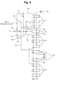
- FIG. 4 is a circuit diagram of a hydraulic circuit for a construction machine having an auto idle function according to another embodiment of the present invention.
- the hydraulic circuit for a construction machine having an auto idle function includes first, second, and third hydraulic pumps P1, P2, and P3; a first switching valve A composed of valves installed in a flow path of the first hydraulic pump P1 and shifted to control hydraulic fluid fed to a right traveling device and working devices (arm, boom, bucket, and so forth); a second switching valve B composed of valves installed in a flow path of the second hydraulic pump P2 and shifted to control hydraulic fluid fed to a left traveling device and working devices (arm, boom, option device, and so forth); a third switching valve C composed of valves installed in a flow path of the third hydraulic pump P3 and shifted to control hydraulic fluid fed to working devices (swing device and so on); a confluence switching valve 8 installed on a downstream side of the flow path of the third hydraulic pump P3 and shifted to selectively supply the hydraulic fluid from the third hydraulic pump P3 to the working devices on the first hydraulic pump side P1 or the working devices on the second hydraulic pump side P2,
- the hydraulic circuit according to another embodiment of the present invention further includes a valve 100 having an inlet that is connected to a flow path connecting the second shuttle valve 42 and the third signal line 32 and an outlet that is connected to a pilot signal line 31 for supplying a pilot signal pressure Pi1 to the confluence switching valve 8.
- the first switching valve A composed of the valves installed in the flow path of the first hydraulic pump P1 and shifted to control the hydraulic fluid fed to the right traveling device and the working devices (arm, boom, and so forth)
- the second switching valve B composed of the valves installed in the flow path of the second hydraulic pump P2 and shifted to control the hydraulic fluid fed to the left traveling device and the working devices (boom, option device, and so forth)
- the third switching valve C composed of the valves installed in the flow path of the third hydraulic pump P3 and shifted to control the hydraulic fluid fed to the working devices (swing device and so on)
- the same drawing reference numerals are used for the same elements across various figures.
- the first shuttle valve 41 compares the pressure of the first signal line 34 in which the signal pressure is formed when the third switching valve C for the working devices connected to the third hydraulic pump P3 is shifted with the pressure of the third signal line 32 in which the signal pressure is formed when the switching valves A and B for the working devices connected to the first and second hydraulic pumps P1 and P2 are shifted, and selects one of the pressures.
- the second shuttle valve 42 compares the pressure selected by the first shuttle valve 41 with the pressure of the second signal line 33 in which the signal pressure is formed when the switching valve D for the traveling devices is shifted, and selects one of the pressures.
- the signal pressure is formed in the signal lines 31, 32, 33, and 34 when the switching valves A, B, C, and D connected to the first, second, and third hydraulic pumps P1, P2, and P3, respectively, and the signal pressure is used as the auto idle pressure.
- the hydraulic circuit for a construction machine has the following advantages.
- the construction of the signal lines in the hydraulic circuit having the confluence circuit and the auto idle signal lines can be simplified and thus the manufacturing cost can be reduced.
- the leakage of the hydraulic fluid through the joint surfaces of the respective switching valves for the working devices and the traveling devices can be minimized, and thus the formed auto idle pressure can be stabilized to heighten the reliability of the hydraulic circuit.
Landscapes
- Engineering & Computer Science (AREA)
- General Engineering & Computer Science (AREA)
- Mining & Mineral Resources (AREA)
- Civil Engineering (AREA)
- Structural Engineering (AREA)
- Physics & Mathematics (AREA)
- Fluid Mechanics (AREA)
- Mechanical Engineering (AREA)
- Operation Control Of Excavators (AREA)
- Fluid-Pressure Circuits (AREA)
Applications Claiming Priority (1)
| Application Number | Priority Date | Filing Date | Title |
|---|---|---|---|
| KR1020060076296A KR100800080B1 (ko) | 2006-08-11 | 2006-08-11 | 건설기계의 유압회로 |
Publications (2)
| Publication Number | Publication Date |
|---|---|
| EP1887149A2 true EP1887149A2 (fr) | 2008-02-13 |
| EP1887149A3 EP1887149A3 (fr) | 2008-08-27 |
Family
ID=38668722
Family Applications (1)
| Application Number | Title | Priority Date | Filing Date |
|---|---|---|---|
| EP07015151A Withdrawn EP1887149A3 (fr) | 2006-08-11 | 2007-08-02 | Circuit hydraulique pour engin de chantier |
Country Status (5)
| Country | Link |
|---|---|
| US (1) | US7721538B2 (fr) |
| EP (1) | EP1887149A3 (fr) |
| JP (1) | JP5086718B2 (fr) |
| KR (1) | KR100800080B1 (fr) |
| CN (1) | CN101122303B (fr) |
Cited By (2)
| Publication number | Priority date | Publication date | Assignee | Title |
|---|---|---|---|---|
| EP3707389A4 (fr) * | 2017-11-08 | 2021-07-14 | Volvo Construction Equipment AB | Circuit hydraulique |
| EP4641029A1 (fr) * | 2024-04-24 | 2025-10-29 | Nabtesco Corporation | Dispositif de soupape de commande directionnelle |
Families Citing this family (11)
| Publication number | Priority date | Publication date | Assignee | Title |
|---|---|---|---|---|
| KR100886476B1 (ko) * | 2007-03-12 | 2009-03-05 | 볼보 컨스트럭션 이키프먼트 홀딩 스웨덴 에이비 | 건설기계용 유압회로 |
| KR100906228B1 (ko) * | 2007-03-30 | 2009-07-07 | 볼보 컨스트럭션 이키프먼트 홀딩 스웨덴 에이비 | 건설중장비용 유압회로 |
| JP5363348B2 (ja) * | 2008-02-20 | 2013-12-11 | 株式会社小松製作所 | 油圧システムおよび油圧システムに用いるバルブ組立体 |
| KR100974277B1 (ko) * | 2008-03-04 | 2010-08-06 | 볼보 컨스트럭션 이키프먼트 홀딩 스웨덴 에이비 | 건설기계의 유압배관 고정장치 |
| JP5311907B2 (ja) * | 2008-07-15 | 2013-10-09 | Ihi建機株式会社 | 建設機械のオートデセル装置用作業状況検出装置 |
| KR101806566B1 (ko) * | 2011-12-28 | 2017-12-08 | 두산인프라코어 주식회사 | 건설기계의 엔진 회전수 제어방법 |
| ITUB20159494A1 (it) * | 2015-12-18 | 2017-06-18 | Walvoil Spa | Valvola direzionale componibile a due o piu' elementi di tipo mista |
| JP2019190226A (ja) * | 2018-04-27 | 2019-10-31 | Kyb株式会社 | 流体圧制御装置 |
| WO2022163303A1 (fr) * | 2021-01-27 | 2022-08-04 | 株式会社クボタ | Machine de travail |
| JP7700035B2 (ja) * | 2021-01-27 | 2025-06-30 | 株式会社クボタ | 作業機 |
| JP7599972B2 (ja) * | 2021-01-27 | 2024-12-16 | 株式会社クボタ | 作業機 |
Family Cites Families (12)
| Publication number | Priority date | Publication date | Assignee | Title |
|---|---|---|---|---|
| JPS55103104A (en) | 1979-02-03 | 1980-08-07 | Kobe Steel Ltd | Hydraulic circuit for hydraulic vehicle |
| KR920006520B1 (ko) * | 1988-06-17 | 1992-08-07 | 가부시끼가이샤 고오베세이꼬오쇼 | 파우어 셔블의 유체제어기구 |
| JP3076210B2 (ja) * | 1995-02-17 | 2000-08-14 | 日立建機株式会社 | 建設機械の油圧駆動装置 |
| JP3681833B2 (ja) * | 1996-09-19 | 2005-08-10 | ヤンマー株式会社 | 掘削旋回作業機の油圧回路 |
| JP3660501B2 (ja) * | 1998-05-28 | 2005-06-15 | 日立建機株式会社 | 建設機械のエンジン回転数制御装置 |
| JP4137431B2 (ja) * | 2001-11-09 | 2008-08-20 | ナブテスコ株式会社 | 油圧回路 |
| JP2004027706A (ja) | 2002-06-27 | 2004-01-29 | Hitachi Constr Mach Co Ltd | 建設機械の油圧回路装置 |
| KR100664369B1 (ko) * | 2002-09-13 | 2007-01-02 | 현대중공업 주식회사 | 굴삭기 옵션장치의 유량합류 장치 |
| JP3992612B2 (ja) * | 2002-12-26 | 2007-10-17 | 株式会社クボタ | バックホウの油圧回路構造 |
| KR100518770B1 (ko) * | 2003-02-12 | 2005-10-05 | 볼보 컨스트럭션 이키프먼트 홀딩 스웨덴 에이비 | 중장비 옵션장치용 유압시스템 |
| KR101081377B1 (ko) * | 2004-12-30 | 2011-11-08 | 두산인프라코어 주식회사 | 굴삭기의 유압펌프 제어시스템 |
| JP3813164B2 (ja) * | 2005-10-11 | 2006-08-23 | 株式会社クボタ | バックホウの油圧装置 |
-
2006
- 2006-08-11 KR KR1020060076296A patent/KR100800080B1/ko not_active Expired - Fee Related
-
2007
- 2007-06-14 US US11/818,549 patent/US7721538B2/en not_active Expired - Fee Related
- 2007-06-28 CN CN2007101271316A patent/CN101122303B/zh not_active Expired - Fee Related
- 2007-07-23 JP JP2007190626A patent/JP5086718B2/ja not_active Expired - Fee Related
- 2007-08-02 EP EP07015151A patent/EP1887149A3/fr not_active Withdrawn
Cited By (2)
| Publication number | Priority date | Publication date | Assignee | Title |
|---|---|---|---|---|
| EP3707389A4 (fr) * | 2017-11-08 | 2021-07-14 | Volvo Construction Equipment AB | Circuit hydraulique |
| EP4641029A1 (fr) * | 2024-04-24 | 2025-10-29 | Nabtesco Corporation | Dispositif de soupape de commande directionnelle |
Also Published As
| Publication number | Publication date |
|---|---|
| US7721538B2 (en) | 2010-05-25 |
| KR100800080B1 (ko) | 2008-02-01 |
| US20080034748A1 (en) | 2008-02-14 |
| EP1887149A3 (fr) | 2008-08-27 |
| CN101122303B (zh) | 2011-11-02 |
| JP2008045741A (ja) | 2008-02-28 |
| CN101122303A (zh) | 2008-02-13 |
| JP5086718B2 (ja) | 2012-11-28 |
Similar Documents
| Publication | Publication Date | Title |
|---|---|---|
| US7721538B2 (en) | Hydraulic circuit for construction machine | |
| US8572957B2 (en) | Hydraulic system for construction equipment | |
| US8607557B2 (en) | Hydraulic control system for excavator | |
| US7614225B2 (en) | Straight traveling hydraulic circuit | |
| US7841175B2 (en) | Hydraulic circuit for construction equipment | |
| US20100000211A1 (en) | Hydraulic control circuit for excavator | |
| EP1970571B1 (fr) | Circuit hydraulique pour machine de construction | |
| EP2772590A1 (fr) | Excavateur hybride comprenant un système d'atténuation des chocs de l'actionneur | |
| JP2001295803A (ja) | 作業機械の油圧駆動装置 | |
| US9702380B2 (en) | Fluid pressure control device for power shovel | |
| KR101669680B1 (ko) | 건설기계의 유압회로 | |
| CN110226010B (zh) | 用于建筑机械的液压控制系统 | |
| EP2039943B1 (fr) | Circuit hydraulique pour équipement lourd | |
| JP5991950B2 (ja) | 建設機械の油圧回路 | |
| JP2001355603A (ja) | 作業機械の油圧駆動装置 | |
| JP2003232305A (ja) | 流体圧回路 |
Legal Events
| Date | Code | Title | Description |
|---|---|---|---|
| PUAI | Public reference made under article 153(3) epc to a published international application that has entered the european phase |
Free format text: ORIGINAL CODE: 0009012 |
|
| AK | Designated contracting states |
Kind code of ref document: A2 Designated state(s): AT BE BG CH CY CZ DE DK EE ES FI FR GB GR HU IE IS IT LI LT LU LV MC MT NL PL PT RO SE SI SK TR |
|
| AX | Request for extension of the european patent |
Extension state: AL BA HR MK YU |
|
| PUAL | Search report despatched |
Free format text: ORIGINAL CODE: 0009013 |
|
| AK | Designated contracting states |
Kind code of ref document: A3 Designated state(s): AT BE BG CH CY CZ DE DK EE ES FI FR GB GR HU IE IS IT LI LT LU LV MC MT NL PL PT RO SE SI SK TR |
|
| AX | Request for extension of the european patent |
Extension state: AL BA HR MK RS |
|
| 17P | Request for examination filed |
Effective date: 20090218 |
|
| 17Q | First examination report despatched |
Effective date: 20090318 |
|
| AKX | Designation fees paid |
Designated state(s): DE FR GB IT |
|
| STAA | Information on the status of an ep patent application or granted ep patent |
Free format text: STATUS: THE APPLICATION IS DEEMED TO BE WITHDRAWN |
|
| 18D | Application deemed to be withdrawn |
Effective date: 20170301 |