EP1887257A1 - Vorrichtung und Verfahren zum Schalten in den Rückwärtsgang für ferngesteuerte manuelle Getriebe - Google Patents
Vorrichtung und Verfahren zum Schalten in den Rückwärtsgang für ferngesteuerte manuelle Getriebe Download PDFInfo
- Publication number
- EP1887257A1 EP1887257A1 EP07301291A EP07301291A EP1887257A1 EP 1887257 A1 EP1887257 A1 EP 1887257A1 EP 07301291 A EP07301291 A EP 07301291A EP 07301291 A EP07301291 A EP 07301291A EP 1887257 A1 EP1887257 A1 EP 1887257A1
- Authority
- EP
- European Patent Office
- Prior art keywords
- reverse
- speed
- shaft
- clutch sleeve
- gear
- Prior art date
- Legal status (The legal status is an assumption and is not a legal conclusion. Google has not performed a legal analysis and makes no representation as to the accuracy of the status listed.)
- Withdrawn
Links
Images

Classifications
-
- F—MECHANICAL ENGINEERING; LIGHTING; HEATING; WEAPONS; BLASTING
- F16—ENGINEERING ELEMENTS AND UNITS; GENERAL MEASURES FOR PRODUCING AND MAINTAINING EFFECTIVE FUNCTIONING OF MACHINES OR INSTALLATIONS; THERMAL INSULATION IN GENERAL
- F16H—GEARING
- F16H3/00—Toothed gearings for conveying rotary motion with variable gear ratio or for reversing rotary motion
- F16H3/02—Toothed gearings for conveying rotary motion with variable gear ratio or for reversing rotary motion without gears having orbital motion
- F16H3/08—Toothed gearings for conveying rotary motion with variable gear ratio or for reversing rotary motion without gears having orbital motion exclusively or essentially with continuously meshing gears, that can be disengaged from their shafts
- F16H3/14—Gearings for reversal only
-
- F—MECHANICAL ENGINEERING; LIGHTING; HEATING; WEAPONS; BLASTING
- F16—ENGINEERING ELEMENTS AND UNITS; GENERAL MEASURES FOR PRODUCING AND MAINTAINING EFFECTIVE FUNCTIONING OF MACHINES OR INSTALLATIONS; THERMAL INSULATION IN GENERAL
- F16H—GEARING
- F16H61/00—Control functions within control units of change-speed- or reversing-gearings for conveying rotary motion ; Control of exclusively fluid gearing, friction gearing, gearings with endless flexible members or other particular types of gearing
- F16H61/04—Smoothing ratio shift
- F16H61/0437—Smoothing ratio shift by using electrical signals
-
- F—MECHANICAL ENGINEERING; LIGHTING; HEATING; WEAPONS; BLASTING
- F16—ENGINEERING ELEMENTS AND UNITS; GENERAL MEASURES FOR PRODUCING AND MAINTAINING EFFECTIVE FUNCTIONING OF MACHINES OR INSTALLATIONS; THERMAL INSULATION IN GENERAL
- F16H—GEARING
- F16H61/00—Control functions within control units of change-speed- or reversing-gearings for conveying rotary motion ; Control of exclusively fluid gearing, friction gearing, gearings with endless flexible members or other particular types of gearing
- F16H61/04—Smoothing ratio shift
- F16H2061/0485—Smoothing ratio shift during range shift from neutral (N) to reverse (R)
-
- F—MECHANICAL ENGINEERING; LIGHTING; HEATING; WEAPONS; BLASTING
- F16—ENGINEERING ELEMENTS AND UNITS; GENERAL MEASURES FOR PRODUCING AND MAINTAINING EFFECTIVE FUNCTIONING OF MACHINES OR INSTALLATIONS; THERMAL INSULATION IN GENERAL
- F16H—GEARING
- F16H61/00—Control functions within control units of change-speed- or reversing-gearings for conveying rotary motion ; Control of exclusively fluid gearing, friction gearing, gearings with endless flexible members or other particular types of gearing
- F16H61/16—Inhibiting or initiating shift during unfavourable conditions , e.g. preventing forward-reverse shift at high vehicle speed, preventing engine overspeed
- F16H2061/165—Preventing reverse gear shifts if vehicle speed is too high for safe shifting
-
- F—MECHANICAL ENGINEERING; LIGHTING; HEATING; WEAPONS; BLASTING
- F16—ENGINEERING ELEMENTS AND UNITS; GENERAL MEASURES FOR PRODUCING AND MAINTAINING EFFECTIVE FUNCTIONING OF MACHINES OR INSTALLATIONS; THERMAL INSULATION IN GENERAL
- F16H—GEARING
- F16H3/00—Toothed gearings for conveying rotary motion with variable gear ratio or for reversing rotary motion
- F16H3/02—Toothed gearings for conveying rotary motion with variable gear ratio or for reversing rotary motion without gears having orbital motion
- F16H3/08—Toothed gearings for conveying rotary motion with variable gear ratio or for reversing rotary motion without gears having orbital motion exclusively or essentially with continuously meshing gears, that can be disengaged from their shafts
- F16H3/12—Toothed gearings for conveying rotary motion with variable gear ratio or for reversing rotary motion without gears having orbital motion exclusively or essentially with continuously meshing gears, that can be disengaged from their shafts with means for synchronisation not incorporated in the clutches
-
- F—MECHANICAL ENGINEERING; LIGHTING; HEATING; WEAPONS; BLASTING
- F16—ENGINEERING ELEMENTS AND UNITS; GENERAL MEASURES FOR PRODUCING AND MAINTAINING EFFECTIVE FUNCTIONING OF MACHINES OR INSTALLATIONS; THERMAL INSULATION IN GENERAL
- F16H—GEARING
- F16H59/00—Control inputs to control units of change-speed- or reversing-gearings for conveying rotary motion
- F16H59/36—Inputs being a function of speed
- F16H59/38—Inputs being a function of speed of gearing elements
-
- F—MECHANICAL ENGINEERING; LIGHTING; HEATING; WEAPONS; BLASTING
- F16—ENGINEERING ELEMENTS AND UNITS; GENERAL MEASURES FOR PRODUCING AND MAINTAINING EFFECTIVE FUNCTIONING OF MACHINES OR INSTALLATIONS; THERMAL INSULATION IN GENERAL
- F16H—GEARING
- F16H59/00—Control inputs to control units of change-speed- or reversing-gearings for conveying rotary motion
- F16H59/36—Inputs being a function of speed
- F16H59/46—Inputs being a function of speed dependent on a comparison between speeds
-
- F—MECHANICAL ENGINEERING; LIGHTING; HEATING; WEAPONS; BLASTING
- F16—ENGINEERING ELEMENTS AND UNITS; GENERAL MEASURES FOR PRODUCING AND MAINTAINING EFFECTIVE FUNCTIONING OF MACHINES OR INSTALLATIONS; THERMAL INSULATION IN GENERAL
- F16H—GEARING
- F16H59/00—Control inputs to control units of change-speed- or reversing-gearings for conveying rotary motion
- F16H59/68—Inputs being a function of gearing status
-
- F—MECHANICAL ENGINEERING; LIGHTING; HEATING; WEAPONS; BLASTING
- F16—ENGINEERING ELEMENTS AND UNITS; GENERAL MEASURES FOR PRODUCING AND MAINTAINING EFFECTIVE FUNCTIONING OF MACHINES OR INSTALLATIONS; THERMAL INSULATION IN GENERAL
- F16H—GEARING
- F16H61/00—Control functions within control units of change-speed- or reversing-gearings for conveying rotary motion ; Control of exclusively fluid gearing, friction gearing, gearings with endless flexible members or other particular types of gearing
- F16H61/68—Control functions within control units of change-speed- or reversing-gearings for conveying rotary motion ; Control of exclusively fluid gearing, friction gearing, gearings with endless flexible members or other particular types of gearing specially adapted for stepped gearings
- F16H61/682—Control functions within control units of change-speed- or reversing-gearings for conveying rotary motion ; Control of exclusively fluid gearing, friction gearing, gearings with endless flexible members or other particular types of gearing specially adapted for stepped gearings with interruption of drive
-
- F—MECHANICAL ENGINEERING; LIGHTING; HEATING; WEAPONS; BLASTING
- F16—ENGINEERING ELEMENTS AND UNITS; GENERAL MEASURES FOR PRODUCING AND MAINTAINING EFFECTIVE FUNCTIONING OF MACHINES OR INSTALLATIONS; THERMAL INSULATION IN GENERAL
- F16H—GEARING
- F16H63/00—Control outputs from the control unit to change-speed- or reversing-gearings for conveying rotary motion or to other devices than the final output mechanism
- F16H63/02—Final output mechanisms therefor; Actuating means for the final output mechanisms
- F16H63/30—Constructional features of the final output mechanisms
- F16H63/302—Final output mechanisms for reversing
Definitions
- the invention relates to a manual gearbox (or mechanical) driven (BVMP) for a vehicle, especially for a motor vehicle, and a device of the gearbox to control the passage of reverse gear.
- BVMP manual gearbox
- BVMP mechanical driven
- Mechanical gearboxes with "classic" architecture use a synchronizer to guarantee a good customer experience when passing reverse gear.
- the reverse synchronizer provides synchronization in rotation between a clutch sleeve secured to a reverse shaft and a reverse gear idly mounted on the reverse shaft. Once the clutch sleeve and the reverse gear rotate at close rotational speeds, the connection between the reverse gear and the clutch sleeve is effected by interconnection.
- the use of a synchronizer prevents crunches when passing the reverse, ensuring the non-clutch report as there is a differential speed between the clutch sleeve and the pinion receiver.
- the cost, the mass and the size of a synchronizer are penalizing.
- the invention uses the information of the sensors present in a controlled box in order to eliminate the synchronizer by replacing it with a control strategy adapted to the passage of reverse gear and, to this end, the invention proposes,
- a gearbox for a vehicle in particular for a motor vehicle, comprising a primary shaft intended to be rotated by a motor, a secondary shaft comprising a secondary gear idly mounted on this secondary shaft, an intermediate shaft intended to drive the wheels of the vehicle in reverse, the secondary gear, driven in rotation by a motor pinion fixed in rotation with the drive shaft, is meshing with a reverse gear mounted idle on a reverse shaft, a coupling in rotation between the drive shaft.
- a reversible clutch sleeve for coupling the walking shaft rear with the reverse gear comprising jaw
- the box further comprising a control member of the reverse clutch sleeve, a first measuring sensor of a magnitude representative of the speed of rotation of the primary shaft a second measurement sensor of a magnitude representative of the speed of rotation of the intermediate shaft, characterized in that it comprises means for controlling the control member of the clutch sleeve adapted to be displaced in axial translation towards the reverse gear of a neutral position in which the reverse gear is free to rotate relative to the reverse shaft to a clutching position in which the sleeve rotatably solidifies the reverse gear and the reverse shaft, the means being configured to prevent the passage of the clutch sleeve in the jaw clutch position blocking the passage of the reverse gearbox as the speed difference between the reverse clutch sleeve and the reverse gear is greater than a predetermined
- control means of the control member of the clutch sleeve comprise a control unit receiving at least the information of the first and second sensors, respectively of the speed of the primary shaft and the speed of the intermediate shaft, as well as a reversing order information of the reverse, the control unit providing control information of the control member of the clutch sleeve.
- the gearbox includes a position sensor of the controller providing feedback information from reverse to the control unit.
- the second measurement sensor is a vehicle speed sensor, the vehicle speed being directly related to the speed of the wheel shaft.
- the speed of the clutch sleeve and the speed of the jaws of the reverse idler gear are respectively calculated one, from the speed of the intermediate shaft and the other from the speed of the primary shaft, taking into account the gear ratios due to the coupling of the motor, secondary and reverse gears.
- the speed of rotation of the wheels and thus of the clutch sleeve is deduced from the speed sensor of the vehicle.
- FIG. 1 represents a partial diagram of the gearbox according to the invention for a motor vehicle.
- the diagram in Figure 1 shows the elements involved in the reverse gear configuration of the gearbox.
- the gearbox of FIG. 1 comprises a primary shaft 10 intended to be rotated by a motor (not shown) via the clutch of the vehicle (not shown), a secondary shaft 12 comprising a secondary gear 14 mounted crazy on the secondary shaft 12, an intermediate shaft 16 for driving the vehicle wheels (not shown) in reverse.
- Rotational coupling between the reverse shaft 24 and the intermediate shaft 16 is achieved by two further pinions 30, 32 meshing, one of the two other pinions being integral with the reverse shaft 24 and the other 32 of the intermediate shaft 16.
- the gearbox comprises a reversible dog clutch sleeve 40 for coupling the reverse shaft 24 with the rear jaw pinion 20.
- the dog clutch sleeve 40 includes claws 42 integral in rotation with each other. the walking tree rear 24, the sleeve 40 can be driven in translation on the reverse shaft 24 by the action of a fork of interconnection 50.
- the gearbox further comprises a first sensor 54 measuring a magnitude representative of the rotation speed Vp of the primary shaft 10, a second sensor 56 measuring a magnitude representative of the rotation speed Vi of the intermediate shaft 16.
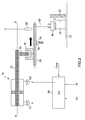
- FIG. 2 shows a block diagram of a control device for actuating the reversible clutch sleeve of the gearbox of FIG. 1.
- the control device comprises a central unit UC 59, an actuator 70 having a control shaft 72 along an axis XX 'that can be moved in one direction, by a command C1 of the actuator, to a position of engagement of the step rearward or, in the opposite direction by a command C2 of the actuator, to a neutral position reverse gear not engaged.
- the control shaft 72 comprises, at one of its ends, a control finger 74 of the fork 50 by means of a control stick 76 integral with one end of the fork 50 having, next to its other end, a finger clutch 80 inserted into a groove of the clutch sleeve 40 of the gearbox.
- the fork 50 comprises between its two ends an indexing means forming a recess 78 for the positioning of a centering ball 79 in the neutral position of the fork 50, this neutral position corresponding to the reverse gear not engaged.
- the control device further comprises a position sensor 90 of the fork 50 indicating the engagement of reverse gear to the control unit UC 59.
- the UC control unit 59 receives at least the information of the first 54 and second sensors 56 respectively of speed Vp of the primary shaft 10 and of the speed Vi of the intermediate shaft 16 and a Cma information of order of passage of the reverse and provides control information C1, C2 of the actuator 70 of the reverse control device.
- the UC control unit 59 compares the difference in rotational speeds at each instant between the rotation speed Vm of the clutch sleeve 40 of reverse and the speed of rotation Vcr of the jaws of the reverse gear 20.
- the speed of rotation Vm of the clutch sleeve is calculated without difficulty from the speed Vi of the intermediate shaft 16 and, the speed of rotation Vcr of the jaws of the idler reverse gear 20 from the speed of the shaft primary 10 taking into account the gear ratios due to the coupling of the motor pinions 18, secondary 12, reverse 20.
- the central unit UC 59 supplies the actuator 70 with the command C2 producing the displacement of its control shaft 72 in the opposite direction of the engagement of the reverse gear (to the left on the 2) producing the decoupling of the clutch sleeve 40 of the reverse gear 20.
- the speed of rotation of the wheels and thus of the clutch sleeve 40 is deduced from the vehicle speed sensor.
- the use of the speed sensor 54 of the primary shaft 10 (present on a driven manual gearbox) associated with the vehicle speed sensor makes it possible to continuously calculate the speed difference between the jaw clutch 40 and the idle gear 20. reverse.
- the drag torque of the gearbox is sufficient to reduce the speed of the primary shaft 10.
- the invention consists in authorizing the clutching of the reverse ratio only when the difference in speed between the clutch sleeve 40 and the reverse gear 21 reaches a determined threshold.
Landscapes
- Engineering & Computer Science (AREA)
- General Engineering & Computer Science (AREA)
- Mechanical Engineering (AREA)
- Control Of Transmission Device (AREA)
- Structure Of Transmissions (AREA)
- Gear-Shifting Mechanisms (AREA)
Applications Claiming Priority (1)
| Application Number | Priority Date | Filing Date | Title |
|---|---|---|---|
| FR0607302A FR2904864B1 (fr) | 2006-08-11 | 2006-08-11 | Dispositif de passage de la marche arriere pour boite de vitesses pilotee |
Publications (1)
| Publication Number | Publication Date |
|---|---|
| EP1887257A1 true EP1887257A1 (de) | 2008-02-13 |
Family
ID=37964542
Family Applications (1)
| Application Number | Title | Priority Date | Filing Date |
|---|---|---|---|
| EP07301291A Withdrawn EP1887257A1 (de) | 2006-08-11 | 2007-08-01 | Vorrichtung und Verfahren zum Schalten in den Rückwärtsgang für ferngesteuerte manuelle Getriebe |
Country Status (2)
| Country | Link |
|---|---|
| EP (1) | EP1887257A1 (de) |
| FR (1) | FR2904864B1 (de) |
Cited By (4)
| Publication number | Priority date | Publication date | Assignee | Title |
|---|---|---|---|---|
| CN101994788A (zh) * | 2009-08-27 | 2011-03-30 | 王有刚 | 机械多档变速器倒档齿轮机构 |
| CN101994787A (zh) * | 2009-08-27 | 2011-03-30 | 王有刚 | 一种机械多挡变速器倒挡齿轮机构 |
| CN116379147A (zh) * | 2023-05-24 | 2023-07-04 | 潍柴动力股份有限公司 | 一种amt挡位判定方法、装置、车辆及存储介质 |
| CN118564643A (zh) * | 2024-08-05 | 2024-08-30 | 中联重科股份有限公司 | 一种换挡控制方法、装置、电子设备及存储介质 |
Citations (2)
| Publication number | Priority date | Publication date | Assignee | Title |
|---|---|---|---|---|
| WO1991010079A1 (en) * | 1989-12-27 | 1991-07-11 | Saab Automobile Aktiebolag | Gearbox for motor vehicles |
| FR2775325A1 (fr) * | 1998-02-20 | 1999-08-27 | New Venture Gear Inc | Systeme de changement de vitesse a commande electronique pour une boite de vitesses a commande manuelle |
-
2006
- 2006-08-11 FR FR0607302A patent/FR2904864B1/fr not_active Expired - Fee Related
-
2007
- 2007-08-01 EP EP07301291A patent/EP1887257A1/de not_active Withdrawn
Patent Citations (2)
| Publication number | Priority date | Publication date | Assignee | Title |
|---|---|---|---|---|
| WO1991010079A1 (en) * | 1989-12-27 | 1991-07-11 | Saab Automobile Aktiebolag | Gearbox for motor vehicles |
| FR2775325A1 (fr) * | 1998-02-20 | 1999-08-27 | New Venture Gear Inc | Systeme de changement de vitesse a commande electronique pour une boite de vitesses a commande manuelle |
Cited By (4)
| Publication number | Priority date | Publication date | Assignee | Title |
|---|---|---|---|---|
| CN101994788A (zh) * | 2009-08-27 | 2011-03-30 | 王有刚 | 机械多档变速器倒档齿轮机构 |
| CN101994787A (zh) * | 2009-08-27 | 2011-03-30 | 王有刚 | 一种机械多挡变速器倒挡齿轮机构 |
| CN116379147A (zh) * | 2023-05-24 | 2023-07-04 | 潍柴动力股份有限公司 | 一种amt挡位判定方法、装置、车辆及存储介质 |
| CN118564643A (zh) * | 2024-08-05 | 2024-08-30 | 中联重科股份有限公司 | 一种换挡控制方法、装置、电子设备及存储介质 |
Also Published As
| Publication number | Publication date |
|---|---|
| FR2904864A1 (fr) | 2008-02-15 |
| FR2904864B1 (fr) | 2009-04-17 |
Similar Documents
| Publication | Publication Date | Title |
|---|---|---|
| CN102308128B (zh) | 变速器的停车锁止装置 | |
| FR2751715A1 (fr) | Procede de controle de fonctionnement d'une transmission de vehicule et vehicule adapte pour l'application de ce procede | |
| EP1887258A1 (de) | Verfahren zur Bestimmung der Anfangs- und Endposition des Einrastens der Klaue einer Klauenkupplung und Getriebe, das die Anfangs- und Endposition der Klauenkupplung beim Schalten abschätzt | |
| EP1496292B1 (de) | Verfahren zum Gangwechsel eines Antriebsstranges der für jedes Antriebsrad einen Schaltmechanismus besitzt | |
| EP2486307B1 (de) | Verfahren zur steuerung eines halbautomatischen getriebes für ein hybrid- oder doppelkupplungsfahrzeug | |
| EP2102527A2 (de) | Verfahren zur änderung der gangstufe in einem getriebe, im wesentlichen für hybridfahrzeuge | |
| WO2008104676A2 (fr) | Procede d'apprentissage d'une grille de boite de vitesses pilotee d'un vehicule hybride, et boite de vitesses notamment pour vehicule hybride | |
| WO2012107679A1 (fr) | Dispositif et procédé pour la commande d'une boite de vitesses a double embrayage | |
| FR2774447A1 (fr) | Vehicule equipe d'un dispositif de manoeuvre automatisee d'une boite a vitesses | |
| FR2904864A1 (fr) | Dispositif de passage de la marche arriere pour boite de vitesses pilotee | |
| EP3417191B1 (de) | Verfahren zur steuerung der entkopplung einer schiebekupplung | |
| FR2987331A1 (fr) | Procede de commande d'un actionneur d'une boite de vitesses et boite de vitesses associee | |
| EP1983228A1 (de) | Optimierungsverfahren für die Steuerung von Synchronisierungsvorrichtungen eines Getriebes beim Verändern des Übersetzungsverhältnisses | |
| EP1983226A1 (de) | Verfahren zur Homogenisierung der Veränderungszeit des Übersetzungsverhältnisses eines Getriebes | |
| EP2199647B1 (de) | Handschaltgetriebe mit einer Synchronisiereinrichtung für den Rückwärtsgang | |
| EP1705406A1 (de) | Kraftfahrzeuggetriebe und Verfahren zum Schalten eines solchen Getriebes | |
| EP2058558A1 (de) | Fahrzeug mit Synchronisierungssystem eines Automatikgetriebes und Steuerungsverfahren dieses Synchronisierungssystems | |
| WO2007093727A2 (fr) | Procede de blocage d'une chaine cinematique de vehicule automobile et de commande d'une transmission automatique avec grille de selection correspondante | |
| EP2063154B1 (de) | Interne Steuervorrichtung des Getriebes eines Kraftfahrzeugs | |
| FR2803888A1 (fr) | Procede de surveillance de la vitesse engagee d'une boite de vitesses automatique | |
| EP2529132A1 (de) | Verfahren zum betrieb eines synchrongetriebes in einem getriebegehäuse | |
| EP2325511A1 (de) | automatisiertes Getriebe | |
| WO2011036394A1 (fr) | Dispositif de synchronisation et de solidarisation des arbres primaires d'une boite de vitesses a double embrayage | |
| FR2914259A1 (fr) | Procede de pilotage d'un changement de rapport de vitesse dans un vehicule hybride en cas de dysfonctionnement de la machine electrique. | |
| FR2712540A1 (fr) | Dispositif d'assistance au débrayage dans les véhicules automobiles. |
Legal Events
| Date | Code | Title | Description |
|---|---|---|---|
| PUAI | Public reference made under article 153(3) epc to a published international application that has entered the european phase |
Free format text: ORIGINAL CODE: 0009012 |
|
| AK | Designated contracting states |
Kind code of ref document: A1 Designated state(s): AT BE BG CH CY CZ DE DK EE ES FI FR GB GR HU IE IS IT LI LT LU LV MC MT NL PL PT RO SE SI SK TR |
|
| AX | Request for extension of the european patent |
Extension state: AL BA HR MK YU |
|
| 17P | Request for examination filed |
Effective date: 20080707 |
|
| 17Q | First examination report despatched |
Effective date: 20080808 |
|
| AKX | Designation fees paid |
Designated state(s): AT BE BG CH CY CZ DE DK EE ES FI FR GB GR HU IE IS IT LI LT LU LV MC MT NL PL PT RO SE SI SK TR |
|
| STAA | Information on the status of an ep patent application or granted ep patent |
Free format text: STATUS: THE APPLICATION IS DEEMED TO BE WITHDRAWN |
|
| 18D | Application deemed to be withdrawn |
Effective date: 20100220 |