EP1887263A1 - Soufflet protecteur - Google Patents
Soufflet protecteur Download PDFInfo
- Publication number
- EP1887263A1 EP1887263A1 EP07015484A EP07015484A EP1887263A1 EP 1887263 A1 EP1887263 A1 EP 1887263A1 EP 07015484 A EP07015484 A EP 07015484A EP 07015484 A EP07015484 A EP 07015484A EP 1887263 A1 EP1887263 A1 EP 1887263A1
- Authority
- EP
- European Patent Office
- Prior art keywords
- bellows
- guide frame
- segment
- connection
- bellow
- Prior art date
- Legal status (The legal status is an assumption and is not a legal conclusion. Google has not performed a legal analysis and makes no representation as to the accuracy of the status listed.)
- Granted
Links
- 230000001681 protective effect Effects 0.000 claims abstract description 58
- 239000000463 material Substances 0.000 claims abstract description 19
- 238000004026 adhesive bonding Methods 0.000 claims abstract description 4
- 229920003023 plastic Polymers 0.000 claims abstract description 4
- 238000003466 welding Methods 0.000 claims abstract description 3
- 238000010276 construction Methods 0.000 claims description 7
- 239000002131 composite material Substances 0.000 claims description 4
- 229920001084 poly(chloroprene) Polymers 0.000 claims description 4
- 239000013013 elastic material Substances 0.000 claims description 2
- 238000003780 insertion Methods 0.000 abstract description 5
- 230000037431 insertion Effects 0.000 abstract description 5
- 238000009434 installation Methods 0.000 description 8
- 238000004519 manufacturing process Methods 0.000 description 5
- 230000008859 change Effects 0.000 description 3
- 230000000694 effects Effects 0.000 description 3
- 238000000034 method Methods 0.000 description 3
- 238000005299 abrasion Methods 0.000 description 2
- 239000000853 adhesive Substances 0.000 description 2
- 230000001070 adhesive effect Effects 0.000 description 2
- 230000008901 benefit Effects 0.000 description 2
- 239000004744 fabric Substances 0.000 description 2
- 239000002184 metal Substances 0.000 description 2
- 238000003825 pressing Methods 0.000 description 2
- 238000000926 separation method Methods 0.000 description 2
- 230000005540 biological transmission Effects 0.000 description 1
- 230000015572 biosynthetic process Effects 0.000 description 1
- 230000001419 dependent effect Effects 0.000 description 1
- 238000000605 extraction Methods 0.000 description 1
- 230000002349 favourable effect Effects 0.000 description 1
- 239000007789 gas Substances 0.000 description 1
- 239000012770 industrial material Substances 0.000 description 1
- 239000011261 inert gas Substances 0.000 description 1
- 238000003475 lamination Methods 0.000 description 1
- 238000012423 maintenance Methods 0.000 description 1
- 230000013011 mating Effects 0.000 description 1
- 230000007935 neutral effect Effects 0.000 description 1
- 230000008569 process Effects 0.000 description 1
- 230000008439 repair process Effects 0.000 description 1
- 239000012858 resilient material Substances 0.000 description 1
- 239000000565 sealant Substances 0.000 description 1
- 238000007789 sealing Methods 0.000 description 1
Images


Classifications
-
- F—MECHANICAL ENGINEERING; LIGHTING; HEATING; WEAPONS; BLASTING
- F16—ENGINEERING ELEMENTS AND UNITS; GENERAL MEASURES FOR PRODUCING AND MAINTAINING EFFECTIVE FUNCTIONING OF MACHINES OR INSTALLATIONS; THERMAL INSULATION IN GENERAL
- F16J—PISTONS; CYLINDERS; SEALINGS
- F16J3/00—Diaphragms; Bellows; Bellows pistons
- F16J3/04—Bellows
- F16J3/041—Non-metallic bellows
- F16J3/042—Fastening details
-
- F—MECHANICAL ENGINEERING; LIGHTING; HEATING; WEAPONS; BLASTING
- F16—ENGINEERING ELEMENTS AND UNITS; GENERAL MEASURES FOR PRODUCING AND MAINTAINING EFFECTIVE FUNCTIONING OF MACHINES OR INSTALLATIONS; THERMAL INSULATION IN GENERAL
- F16J—PISTONS; CYLINDERS; SEALINGS
- F16J3/00—Diaphragms; Bellows; Bellows pistons
- F16J3/04—Bellows
- F16J3/048—Bellows with guiding or supporting means
Definitions
- the invention relates to a bellows according to the preamble of patent claim 1, which consists of a juxtaposition of individual Schutzbalgsegmente, wherein a single Schutzbalgsegment comprises a substantially cylindrical bellows segment, a guide frame and at least one pinhole.
- bellows which are constructed of a flexible plastic-like material, wherein the individual Faltenbalgsegmente were constructed of individual circular PVC rings, which are glued or welded together.
- receiving devices are provided in the center of each flank which connects a mountain with a valley of the protective bellows, in which pinhole apertures can be accommodated.
- U1 is a bellows with a preferably closed bellows body out, which is encompassed by at least one guide frame which is in positive engagement with the bellows body.
- the guide frame is formed flat and has at least one separation point, wherein the separation point is overlapped by at least one voltage applied to the guide frame, surface connecting element.
- the patent DE 101 37 803 B4 discloses a cylindrical laser bellows with around a central longitudinal axis circumferentially closed, folded bellows material with inner and outer folds and with inserted in the outer fold metal apertures, the aufciscn a circular cylindrical aperture.
- the metal panels are in the middle of a fold edge, the inner and outer folds connects, arranged there because the radius of the bellows does not change when moving out (neutral diameter).
- a disadvantage of the known from the prior art bellows is firstly that the structure of each Faltenbalgssegments very complicated in terms of choice of material (fabric with lamination or individually gendergcklcbte bellows rings) is realized, on the other hand, the arrangement of the receiving bracket for the pinhole within the bellows a greater constructive effort and complicated work processes necessary.
- the complex structure of the known bellows leads to high costs in the assembly and maintenance as well as the use of many items that drive up the overall cost of the bellows in the air.
- the bellows according to the invention consists of a juxtaposition of individual bellows segments, wherein a single bellows segment comprises a substantially cylindrical bellows segment, a guide frame and at least one pinhole.
- the bellows is inventively characterized in that the bellows segment is made in one piece from a flexible bellows material, wherein at the bellows segment at its two axial ends connecting elements are arranged for connection to adjacent bellows segments, and at least one of the two ends fastening elements for fixing the Faltenbalgsegments with the guide frame are arranged, and at least one of the two ends receiving elements for receiving and I-aging Aperture are arranged.
- a bellows segment consists of only three basic components: a one-piece bellows segment, a guide frame and a pinhole.
- the bellows segment is equipped so that it has at least at one of its two ends connecting means for connecting the Faltenbalgsegment with the respective subsequent Faltenbalgsegment, in turn at one of the two ends fastening elements for attachment to the guide frame, and in turn at one of the two ends receiving elements for Recording and holding the pinhole has. It follows that at least one pinhole can be attached to each bellows segment, and this is always arranged in the region of the guide frame.
- a particularly advantageous embodiment of the protective bellows results from the fact that the guide frame and the pinhole are arranged substantially in one plane. Because pinhole and guide frame are to be arranged in the region of the axial end of a bellows segment, it is obvious that they can be arranged in one plane. This results in the advantage that the guide frame can additionally stabilize the recording of the pinhole, and further the support of the bellows is supported in the guide frame from the inside through the pinhole, so that guide frame and pinhole when placed in a plane from the inside and outside forces on the Be able to exert connection point adjacent bellows segments and thus support a gas-tight connection between two adjacent Faltenbalgsegmenten.
- each bellows segment does not end with a mountain and / or valley fold, but at its end still has a projection which is shaped as a spout.
- end grommets allow the attachment of suitable connecting, fastening and receiving elements, on the one hand to establish the connection between two adjacent bellows segments, on the other hand to realize the attachment to the guide frame, and thirdly to ensure the ability to accommodate and hold the pinhole.
- the arrangement of these connection, Bcfest Trents and receiving elements on the end grommets reduces the number of required items for assembly of the protective bellows and facilitates the assembly considerably.
- connection possibilities of the bellows segments are possible.
- a possibility described below is based on the fact that the end bellows of the adjacent bellows segments are formed in such a way that they interlock and thus already contribute to the connection.
- special connection and fastening means are arranged on the end grommets for connection of the bellows segments and fastening of the guide frame, this variant will be explained later in the description.
- a first of the two axial end grommets of the bellows has an inner radius ⁇ dem the outer diameter of the second of the two axial Endtüllen, so that two adjacent Faltenbalgsegmente by inserting the second Endtülle the second bellows segment can be connected to each other in the first end of the adjacent first Faltenbalgsegments.
- a final spout larger than the other end spout of each bellows segment are made possible, but this has the consequence that the Faltenbalgsegmente are no longer end symmetric, and have a designated installation or installation direction.
- the connecting elements of the two end sleeves of the bellows segment have at least one connecting lip surrounding the inner jacket of the first end sleeve and at least comprise a connecting fold circumscribing on the outer jacket of the second end sleeve, so that the connecting lip of the first end sleeve of a first bellows segment makes a positive connection by snapping into the connecting fold of the second end sleeve of a second adjacent bellows segment.
- the connecting lip can be arranged on the one hand on the outer shell of the smaller-shaped Endtülle or on the inner shell of the larger-sized Endtülle, and arranged according to the kausfalz on the outer jacket of the smaller or on the inner shell of the larger Endtülle.
- a connecting lip of a Endtülle engages in a kausfalz the other end grommet when the two end grommets are pushed into each other with different diameters.
- Such an embodiment of the connecting elements allows a tool-free connection of two adjacent bellows segments, wherein the sealing effect is mainly supported by an inner of the bellows arranged aperture and an encompassing from the outside guide frame.
- the fastening elements for fastening the bellows segment to the guide frame to comprise a fastening groove encircling the outer jacket of the first end sleeve into which the guide frame positively engages.
- the first Endtülle is the Endtülle with each larger inner diameter, which can be pushed over the second end sleeve of the adjacent Faltenbalgsegments.
- this larger first Endtülle may advantageously be recessed a circumferential mounting groove, which then serves as a receptacle for a mostly thin plate-shaped guide frame, which engages positively in the mounting groove.
- the guide frame exert pressure on the connection point of the two Faltenbalgsegmente by embracing the Endtülle, and improve the positive connection and gas-tight property of this, joint.
- the guide frame has a substantially circular recess whose diameter is substantially smaller than or equal to the diameter of the fastening groove.
- the guide frame can be made in one piece, and the first end grommet of a Faltenbalgsegments be secured in the guide frame by snapping the mounting groove in the guide frame. If, for example, the adjacent bellows segment is then inserted into the first snapped-in end grommet and secured, for example, with the above-mentioned connecting lip and connecting fold, a connection is created between two bellows segments, which are also connected to a guide frame and moved in and out along a guide rail can.
- the bellows segment is fastened by a form-fitting snapping in of the fastening groove in a recess of the guide frame.
- the guide frame is constructed in several parts, in particular two parts, and the bellows segment is connected to the guide frame in that the individual parts of the guide frame in the mounting groove of the Faltenbalgsegments inserted and then the parts of the guide frame are connected to each other in particular with attackssrahmenvbr Kunststoffsstoff.
- the guide frame can be placed over the junction of the two Faltenbalgsegmente, and by connecting the two parts, for example with witnessessrahmeneducationsstoff or by overlapping the items of the guide frame and non-positive connection of the items by rivets, screws, adhesive, etc.
- the guide frame is made in two or more parts, then it is particularly advantageous that by fixing the guide frame connecting means for connecting the individual parts of the guide frame of the total composite of the two connected Faltenbalgsegmenten, pinhole and guide frame is positively and positively fixed and secured.
- the pinhole is substantially in the plane of the guide frame by pushing the guide frame over the two end grommets of the bellows segments and connecting the two parts of the guide frame by attackssrahmeneducationsstoff a pressure of the guide frame on the outer circumferential surface of the nested Endtüllen constructed by the pinhole disposed inside the Endtüllen can be added.
- the guide frame connecting means are the essential elements of the assembly of the protective bellows, since they at the joints of two bellows as only have to establish the connection of the guide frame to connect the entire composite of adjacent bellows segments frictionally, positively and gas-tight.
- the guide frame is made in several parts, it is particularly advantageous and recommended that the individual parts of the guide frame engage in one another in a form-fitting manner and are fixed against one another by means of fixing lugs.
- individual stressessnasenaus- and -inbuchtitch can be provided on the guide frame, so that the items of the guide frame with the help of these fixing lugs engage each other and allow a precisely fitting connection of the individual parts of the guide frame.
- the assembly time can be significantly shortened and the accuracy of fit in the production of the bellows can be increased.
- the guide frame serves to movably guide the protective bellows within a guide rail.
- the guide frame it is advantageously possible for the guide frame to have a guide holder in order to displaceably hold and guide the guide frame on guide rails.
- the guide holder can be designed arbitrarily, in practice it has been shown that the guide holder usually consists of two encompassing brackets, which engage either from the inside in twolvessgleitkanten a guide rail, or engage around two substancessgleitkanten from the outside. It is possible that the guide holder from the outside only a single guide rail having twoêtsgleitkanten includes.
- sliding elements can be attached, which improve the sliding and abrasion resistance of the guide frame along the guide rail.
- the inclusion of the pinhole within the protective bellows can be performed arbitrarily. Consistent with the above statements regarding the fastening elements on the guide frame, it is advantageously possible that the receiving elements for receiving and holding the pinhole a circumferential groove surrounding the inner shell of the second Endtülle include.
- the second Endtülle is the Endtülle, which has the smaller outer diameter and smaller inner diameter, and which is inserted into the first Endtülle an adjacent bellows segment.
- this second Endtülle comprises an internally encircling receiving groove
- the pinhole which is designed in most cases as a circular disc with aperture hole
- the pinhole are received and stored in this receiving groove.
- the circular pinhole has an inner diameter which is substantially equal to the diameter of the receiving groove, so that the pinhole can be snapped securely into the receiving groove, since the bellows material is usually made of an elastic, flexible material.
- the relative position of the fastening groove for fastening the bellows segment on the guide frame to the receiving groove for holding and receiving the pinhole is arbitrary.
- the circumferential mounting groove of the first Endtülle of the first Faltenbalgsegments is substantially in the plane of the circumferential receiving groove of the second Endtülle the second Faltenbalgsegments, so that in the Receiving groove of the second end grommet of the second bellows segment recorded pinhole is substantially in the same plane as the fixed in the mounting groove of the first Endtülle the first Faltenbalgsegments guide frame.
- the receiving groove which is located on the outer circumferential surface of the first Endtülle, in the inserted state of the first and second Endtülle in the same plane as the provided in the inner shell of the second Endtülle receiving groove of the pinhole.
- the guide frame and pinhole form a common plane, and fill the joint of two adjacent bellows segments so that the pressure exerted by the guide frame on the joint can be absorbed by the inner pinhole.
- connection fastening panel preferably consists essentially of an aperture ring and two outer edges.
- the two flanks engage around the end grommets of the two adjacent Faltenbalgsegmente, wherein in the region of the diaphragm ring between the two End grommets engages the recess of the guide frame.
- the connection attachment panel assumes the function of a connecting element and a fastener and can also take over the function of a pinhole.
- connection fastening panel consists of an elastic material, in particular plastic.
- connection attachment panel is constructed in two parts, and comprises an outer and an inner panel. Due to the snug fit mating of outer diaphragm ring via inner diaphragm ring results in a kausbefest Trentsblende, the outer diaphragm flank of the outer panel and the inner panel flank of the inner panel, the two end grommets of the adjacent Falkenbalgsegmente and the interposed recess of the guide frame clamps and thus realizes the connection or attachment. As a result, a particularly simple installation of the bellows is possible.
- connection fastening panel is constructed in two parts, it is obvious that the outer panel and the inner panel can be connected to one another by a snap-lock connection. This allows a tool-free and fast installation.
- connection mounting bracket Deviating from a two-piece version of the connection mounting bracket and a connection of outer panel with inner panel by gluing, welding or the like is conceivable.
- Deviating from the connecting attachment panel can advantageously be constructed in one piece. This reduces the manufacturing costs and the number of component components, and does not require additional connection of the individual parts of the connection fastening panel.
- connection mounting panel meet in this embodiment, the main task of the connection and attachment.
- the diaphragm flanks have inwardly directed circumferential engagement edges which engage in the Endtüllen the Faltenbalgsegmente. With the aid of such engagement edges, the connection reliability of the bellows segments is increased, especially at high dynamic loads when the protective bellows are inserted and removed.
- connection fastening panel comprises at least one receiving element for receiving and holding a pinhole.
- connection attachment panel takes over the functions of the pinhole.
- the function of a pinhole is extended to a kausbefest Trentsblende, thereby saving material, installation costs and time.
- the material of which the bellows segments are made is arbitrary. However, it is particularly advantageous if the bellows segments are made of a gas-tight, elastic and flexible material, preferably of CR (chlorobutadiene rubber). Especially these materials have a high wear resistance, high flexibility and are ideal for the production of bellows segments. With regard to operational safety, a self-extinguishing effect of the material is to be preferred. In particular, it is advantageous and in part a basic requirement for the material of the protective bellows that it conforms to the UL94-VO industrial material standard.
- the inventive protective bellows can be used in particular for covering and protecting a laser beam.
- the inner atmosphere of the protective bellows should meet certain requirements, e.g. a high purity.
- such bellows are usually performed gas-tight. Therefore, it is a fundamental requirement of the connecting elements of two adjacent bellows segments, that the connection of adjacent bellows segments with attached guide frame and recorded pinhole gas-tight.
- This gas-tight effect can be realized, for example, by the use of additional sealants such as adhesives or additional connection and fastening means.
- positioning aids are attached to the guide frame and / or the bellows segment, with the aid of which an equal angular orientation of the guide frame relative to the longitudinal axis of the bellows is facilitated.
- a positioning aid can for example consist of one or more Positionicrungsnasen, which engage positively in recesses of the respective counterpart.
- a positioning nose can be provided in the fastening groove of a bellows segment, which dips into a positioning slot on the circumference of the guide frame recess.
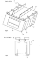
- FIG. 1 a conventional embodiment of a protective bellows 03 according to the prior art is shown in a schematic perspective view.
- the protective bellows system 01 according to the prior art comprises a guide rail 02, which consists of a guide plate and two top-mounted support rails, and in which the guide frame 04 of the bellows 03 is fixed by means of guide frame mounts.
- the protective bellows 03 consists of bellows segments 05, which connect the individual guide frames 04. Both the guide frame and the Schutzbalgsegmente 05 are designed rectangular.
- the rectangular guide frame 04 has a rectangular pinhole 06. At the guide frame 04 slide rails are mounted in the region of the guide frame holders, which facilitate the sliding of the guide frame along the guide rail 02.
- Fig. 2 shows the usual structure of a guide frame 07 according to the prior art, which has a rectangular contour.
- the guide frame 04 consists of four individual parts, by means of Guide frame connecting means - in this case rivets - are connected.
- the two lateral guide frame parts on guide brackets 09 which can be reinforced with slide rails, and can engage in guide rails in the example shown in a substantially U-shaped guide rail with the help of the guide brackets from the inside.
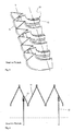
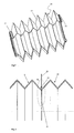
- Fig. 3 shows a perspective schematic sectional view of an area of a Faltenbalgsegments 10 according to the prior art.
- the bellows segment 10 consists of individual successively arranged folds 11 which are connected to each other in a zigzag, and in the middle of its flank a receiving element 13 for have a pinhole 12.
- a pinhole 12 are received in each fold 11 of the Faltenbalgsegments 10.
- the arrangement of the receiving element 13 of the pinhole 12 in each case in the middle of the edge of a fold 11 ensures a constant radius of the receiving element 13, which does not change even during retraction and extension of the bellows segment 10.
- FIG. 4 shows a sectional view of a 2D portion of the bellows segment 10 shown in FIG. 3, which is shown only half due to its rotational symmetry.
- a receiving element 13 of a pinhole 12 is arranged, which can accommodate a disk-shaped pinhole 12, which has a large outer and a small inner radius.
- the arrangement of the receiving element of the pinhole 13 in the middle of a flank of a fold 11 allows a constant radius of the receiving element even with extreme insertion and extraction of Faltenbalgsegments so that the pinhole 12 12 finds a firm and secure hold in any pullout situation.
- the schematic perspective view of a cut-open bellows segment 14 of FIG. 5 shows a first embodiment of a bellows segment according to the invention.
- the bellows segment 14 includes six folds 15 and is bounded at its axial ends by a first end grommet 17 and a second end grommet 16.
- the two end grommets 16 and 17 of the bellows segment 14 have connection, receiving and fastening elements.
- the outer radius of the second Endtülle 16 is equal to the inner radius of the first Endtülle 17, so that the second Endtülle 16 can be inserted into the first Endtülle 17 of an adjacent identical bellows 14, wherein a dacasfalz the second Endtülle 16 in a connecting lip the first Endtggle 17 can engage.
- Fig. 6 is a schematic sectional view of the connecting region of two Faltenbalgsegmente 18 and 19 of the first embodiment shown.
- a first bellows segment 18 is connected to a second bellows segment 19 in which the two end sleeves of the two Faltenbalgsegmente 18 and 19 overlap and their connecting elements 22 produce a gas-tight, non-positive and positive connection.
- the end grommets is also a receiving device for a pinhole 21 and fasteners for attachment to a guide frame 20, both of which also engage in the connection / mounting / receiving elements 22.
- the overlapping area is marked as detail area A.
- the detail area A of FIG. 6 is shown enlarged in FIG. 7 . It can be clearly seen how the connecting elements of the first end sleeve 28 engage in the connecting elements of the second end sleeve 27 of the two adjacent bellows segments 18 and 19.
- the first Endtülle 28 has an inner radius which is equal to the outer radius of the second Endtülle 27.
- the first Endtülle 28 includes a connecting lip 24 which engages in a kausfalz 23 of the second Endtülle 27.
- the second end sleeve 27 of the second bellows segment 19 further comprises a receiving groove 26 for receiving and holding a circular pinhole 21, which with its outer shell in the Receiving groove 26 of the second Endtülle 27 engages.
- the first Endtülle 28 of the first Faltenbalgsegments 18 includes a mounting groove 25 in which a guide frame 20 engages positively and non-positively.
- the mounting groove 25 of the first Endtülle 28 is disposed in the same plane as the receiving groove 26 of the second Endtülle 27, so that the overall composite of guide frame 20, mounting groove 25 of the first Endtülle 28, receiving groove 26 of the second Endtülle 27, and pinhole 21 in a plane is arranged so that by connecting pressure of the guide frame 20, this pressure is transferred directly to the pinhole 21, and thus the connecting elements 24 and 23 of the two Faltenbalgsegmente 18 and 19 effectively in creating a gas-tight force and zugübertragenden connection of the two adjacent Faltenbalgsegmente 18 and 19th supported.
- Fig. 8 shows a schematic perspective view of a possible embodiment of a guide frame 29 according to the invention.
- the guide frame 29 consists of an upper part 32 and a lower part 33, which are shown in a collapsed state.
- the upper part 32 for ease of attachment fixing lugs 36 and can be positively inserted into the lower part 33 of the guide frame.
- a circular effetsrahmenaus strictlyung 34 in which, for example, the mounting groove 25 dc; r first Endtülle 28 of FIG. 7 can engage, so by frictional connection of the upper and lower part of Guide frame 29 by guide frame connecting means 35 pressure on the junction of two adjacent bellows segments 18 and 19 can be exercised.
- the guide frame 29 further comprises two guide brackets 31, which clasp a guide rail 30 from the outside in a clamp-like manner, the guide brackets 31 being reinforced with slide rail elements for easier mobility and increased abrasion resistance.
- connection of two bellows segments 37 and 38 of the first embodiment is shown in a schematic perspective and broken view.
- the first end grommet of the bellows segment 38 is pushed over the second end grommet of the bellows segment 37, so that at this point the connecting elements of the two grommets overlap and a connection / mounting / receiving element region 39 is formed, which may have the structure shown in FIG. 7 , for example.
- a circumferential mounting groove is provided, in which a guide frame and non-positively engage positively, and in the inner shell region of the second Endtülle of the second Faltenbalgsegments 37 a receiving holder for a pinhole is provided.
- a first Endtülle 40 and a second Endtülle 41 is arranged so that more Faltenbalgsegmente can be connected to the already connected Faltenbalgsegmente.
- FIG. 10 shows in an extension of the configuration shown in Fig. 9 , the two Faltenbalgsegmente 37 and 38, at their connection / mounting / receiving elements 39, a guide frame 42, which may correspond, for example, the guide frame shown in Fig. 8 , attached.
- this bellows segment consisting of two bellows segments is prepared for installation, and can for example be attached to an existing protective bellows.
- FIG. 10 a shows the overall configuration described above, while FIG. 10 b provides a broken view in which it is possible to look into the interior of the bellows segment 45.
- the position of the perforated plate 44 which is received and held in the receiving element of the connecting / fastening / receiving elements 39 can be detected.
- FIG. 11 shows, in a perspective schematic illustration, an entire protective bellows 46 of an exemplary embodiment which consists of individual bellows segments 45.
- the bellows 46 comprises in the illustrated configuration six bellows segments 45, each bellows segment 45 consisting of a guide frame 42, a bellows segment 45 and a pinhole 48.
- the guide frame 42 are suspended in double-pair guide rails 49 and slidably movable.
- Fig. 12 shows the protective bellows 46 shown in Fig. 11 in a broken view, and leaves the view into the interior of the bellows 46 free.
- the bellows 46 which consists of six bellows segments 45, comprises bellows segments 47, guide frames 42 and pinhole diaphragms 48. In this case, one of the two guide rails 49 can be seen in FIG .
- FIG. 13 shows a two-part embodiment of a connection fastening panel of a second exemplary embodiment.
- a two-part connection fastening panel 50 consists of an outer panel 51 and an inner panel 52.
- Each of these two partial panels 51, 52 comprises an aperture ring 58 or 59 and an aperture end edge 57 or 60.
- outer panel 52 and inner panel 51 are of identical construction
- the outer panel 52 has an inner radius of the diaphragm ring 58, which corresponds to the outer radius of the diaphragm ring 59 of the inner panel 51 substantially.
- the outer aperture ring 58 can be slid over the inner aperture ring 59, so that by pushing together the outer panel 52 and inner panel 51, the connection fastening panel 50, as shown in Fig. 13b , results.
- a bellows segment 54 of a second and third embodiment is shown in cutaway perspective view.
- the bellows segment 54 consists of 3 folds and is delimited at its two axial ends by two end sleeves 55.
- the end grommets 55 are in contrast to the bellows segment 14 shown in Figure 5 identically shaped, so that the bellows 54 has no preferred direction.
- the width of the aperture rings 58, 59 of the connection fastening panel 50 is selected so that between the two outer edges 57, 60 two end sleeves 55 of adjacent bellows segments 55 and the width of the edge of the recess of a guide frame 53 can engage.
- connection of two adjacent Faltenbalgsegmente 54 and the attachment to a guide frame 53 is effected in that both inner 51 and outer panel 52 are inserted through one of the two adjacent Endtüllen 55 and the intervening recess of the guide frame 53, so that the two partial panels 51st , 52 connect by latching, gluing or other connection techniques to the connection mounting bracket 50.
- Fig. 15 the connecting portion of two Faltenbalgsegmente 54 is shown in perspective in detail.
- a guide frame 53 is arranged between the two end sleeves 55 of the adjacent bellows segments 54.
- the flanks 57, 60 of the two telescoping panel parts 51, 52 of the connection fastening panel 50 surround the two end sleeves 55 of the adjacent bellows segments 54 with the intermediate recess of the guide frame 53, and thus connect the two bellows segments 54 and fasten them to the guide frame 53.
- FIG. 16 shows a three-dimensional representation of a one-piece connection fastening panel 56.
- the connecting fastening panel 56 comprises an aperture ring 61 and two panel flanks 62.
- the width of the panel ring 61 is designed so that the groove formed by the two panel flanks 62 and the aperture ring 61 surround the two end sleeves 55 of adjacent bellows segments 54 and the width of the recess of a guide frame 53 can.
- the two diaphragm flanks 62 have at their radially outermost edge two inwardly directed engagement edges 63. This serves to allow by crushing the soft, resilient material of the end grommets 55 improved power transmission and connection.
- FIG. 17 shows a perspective cutaway view of a Faltenbalgsegment 54 with its two identical end grommets 55. On the left of the two end grommets 55 is a one-piece Kausbefest onlysblende 56 is arranged, which encloses the Endtülle 55.
- FIG. 18 subsequently shows, in a perspective detail view, the connection of two adjacent bellows segments 54 by receiving their adjacent end grommets 55 into the groove of the connecting fastening panel 56 formed by the two diaphragm flanks 62 and the diaphragm ring 61.
- FIG. 19 shows the FIG. 19 in a corresponding perspective detail illustration adjacent the junction of the two Faltenbalgsegmente 54 additionally to be arranged between the two end sleeves 55 lead frame 53 with the edge of its recess also in the groove of the connection mounting aperture 56 intervenes.
- FIG. 19b shows, in a cutaway perspective view, two adjacent bellows segments 54 of a protective bellows, which are connected to one another by means of the one-piece connection fastening panel 56 and fastened to the guide frame 53.
Landscapes
- Engineering & Computer Science (AREA)
- General Engineering & Computer Science (AREA)
- Mechanical Engineering (AREA)
- Diaphragms And Bellows (AREA)
Applications Claiming Priority (1)
| Application Number | Priority Date | Filing Date | Title |
|---|---|---|---|
| DE200610037918 DE102006037918B4 (de) | 2006-08-11 | 2006-08-11 | Schutzbalg |
Publications (2)
| Publication Number | Publication Date |
|---|---|
| EP1887263A1 true EP1887263A1 (fr) | 2008-02-13 |
| EP1887263B1 EP1887263B1 (fr) | 2010-03-24 |
Family
ID=38669184
Family Applications (1)
| Application Number | Title | Priority Date | Filing Date |
|---|---|---|---|
| EP20070015484 Ceased EP1887263B1 (fr) | 2006-08-11 | 2007-08-07 | Soufflet protecteur |
Country Status (2)
| Country | Link |
|---|---|
| EP (1) | EP1887263B1 (fr) |
| DE (2) | DE102006037918B4 (fr) |
Cited By (5)
| Publication number | Priority date | Publication date | Assignee | Title |
|---|---|---|---|---|
| DE102009040729B4 (de) * | 2009-09-09 | 2015-03-12 | Airbus Defence and Space GmbH | Verbindungselement für einen modularen, flexiblen Verbindungskanal |
| AT519939A1 (de) * | 2017-05-08 | 2018-11-15 | Vat Holding Ag | Führungseinrichtung für einen Membranbalg |
| CN112703025A (zh) * | 2018-09-14 | 2021-04-23 | 贝克顿·迪金森公司 | 可塌缩注射器筒消毒帽 |
| CN113785760A (zh) * | 2021-09-16 | 2021-12-14 | 山东中建八局投资建设有限公司 | 一种园林绿化用幼苗供水浇灌装置 |
| US20220268360A1 (en) * | 2021-02-11 | 2022-08-25 | Tco As | Metal Bellows for Downhole Use |
Families Citing this family (3)
| Publication number | Priority date | Publication date | Assignee | Title |
|---|---|---|---|---|
| DE102013014771A1 (de) | 2013-09-05 | 2015-03-19 | Hema Maschinen- Und Apparateschutz Gmbh | Schutzbalg aus Schutzbalgsegmenten |
| EP2899433B1 (fr) * | 2014-01-28 | 2016-11-23 | P.E.I. Protezioni Elaborazioni Industriali S.r.l. | Soufflet de protection et procédé de protection pour machine-outil avec un dispositif de traitement laser |
| DE102016206295B3 (de) * | 2016-04-14 | 2017-10-05 | Schaeffler Technologies AG & Co. KG | Nehmerzylinder, Schmutzschutzvorrichtung und Verfahren zum Montieren einer Schmutzschutzvorrichtunq |
Citations (6)
| Publication number | Priority date | Publication date | Assignee | Title |
|---|---|---|---|---|
| FR1279424A (fr) * | 1960-11-09 | 1961-12-22 | Turover | Perfectionnements à la fabrication de gaines extensibles de protection |
| GB1056660A (en) * | 1965-12-04 | 1967-01-25 | Henry Beakbane Fortox Ltd | Improvements in covers for reciprocating machinery parts |
| JP2000161487A (ja) * | 1998-11-30 | 2000-06-16 | Mitsubishi Electric Corp | レーザ装置用蛇腹 |
| DE10137803A1 (de) | 2000-02-07 | 2003-02-27 | Moeller Werke Gmbh | Zylindrischer Laserschutzbalg |
| JP2003245790A (ja) * | 2002-02-21 | 2003-09-02 | Daihen Corp | レーザ加工機 |
| DE202004005303U1 (de) | 2004-03-31 | 2004-06-24 | Arno Arnold Gmbh | Faltenbalg |
-
2006
- 2006-08-11 DE DE200610037918 patent/DE102006037918B4/de not_active Expired - Fee Related
-
2007
- 2007-08-07 EP EP20070015484 patent/EP1887263B1/fr not_active Ceased
- 2007-08-07 DE DE200750003199 patent/DE502007003199D1/de active Active
Patent Citations (6)
| Publication number | Priority date | Publication date | Assignee | Title |
|---|---|---|---|---|
| FR1279424A (fr) * | 1960-11-09 | 1961-12-22 | Turover | Perfectionnements à la fabrication de gaines extensibles de protection |
| GB1056660A (en) * | 1965-12-04 | 1967-01-25 | Henry Beakbane Fortox Ltd | Improvements in covers for reciprocating machinery parts |
| JP2000161487A (ja) * | 1998-11-30 | 2000-06-16 | Mitsubishi Electric Corp | レーザ装置用蛇腹 |
| DE10137803A1 (de) | 2000-02-07 | 2003-02-27 | Moeller Werke Gmbh | Zylindrischer Laserschutzbalg |
| JP2003245790A (ja) * | 2002-02-21 | 2003-09-02 | Daihen Corp | レーザ加工機 |
| DE202004005303U1 (de) | 2004-03-31 | 2004-06-24 | Arno Arnold Gmbh | Faltenbalg |
Cited By (7)
| Publication number | Priority date | Publication date | Assignee | Title |
|---|---|---|---|---|
| DE102009040729B4 (de) * | 2009-09-09 | 2015-03-12 | Airbus Defence and Space GmbH | Verbindungselement für einen modularen, flexiblen Verbindungskanal |
| AT519939A1 (de) * | 2017-05-08 | 2018-11-15 | Vat Holding Ag | Führungseinrichtung für einen Membranbalg |
| CN112703025A (zh) * | 2018-09-14 | 2021-04-23 | 贝克顿·迪金森公司 | 可塌缩注射器筒消毒帽 |
| CN112703025B (zh) * | 2018-09-14 | 2023-04-21 | 贝克顿·迪金森公司 | 可塌缩注射器筒消毒帽 |
| US20220268360A1 (en) * | 2021-02-11 | 2022-08-25 | Tco As | Metal Bellows for Downhole Use |
| US12253175B2 (en) * | 2021-02-11 | 2025-03-18 | Tco As | Metal bellows for downhole use |
| CN113785760A (zh) * | 2021-09-16 | 2021-12-14 | 山东中建八局投资建设有限公司 | 一种园林绿化用幼苗供水浇灌装置 |
Also Published As
| Publication number | Publication date |
|---|---|
| DE502007003199D1 (de) | 2010-05-06 |
| EP1887263B1 (fr) | 2010-03-24 |
| DE102006037918A1 (de) | 2008-02-14 |
| DE102006037918B4 (de) | 2008-11-06 |
Similar Documents
| Publication | Publication Date | Title |
|---|---|---|
| EP1887263B1 (fr) | Soufflet protecteur | |
| EP1517048A2 (fr) | Accumulateur hydropneumatique | |
| DE102011113388A1 (de) | Schutzabdeckung | |
| DE10301018A1 (de) | Anordnung zum Verbinden eines rohrförmigen ersten Bauteils mit einem zweiten Bauteil sowie Verfahren zur Herstellung einer solchen Anordnung | |
| EP3701109A1 (fr) | Fenêtre d'inspection pour systèmes de cvc et chambres climatiques | |
| EP0403937B1 (fr) | Manchon universel à tuyau de manchon divisé longitudinalement et corps frontaux d'étanchéité | |
| DE2324209A1 (de) | Befestigungsauge | |
| DE69098T1 (de) | Rohrfoermiges verbindungsstueck. | |
| DE19515860A1 (de) | Befestigungsvorrichtung für Bauteile, insbesondere für Schlauch-, Rohranschlüsse oder dergleichen | |
| EP0634599A1 (fr) | Raccord de tuyaux flexible | |
| DE202006012444U1 (de) | Schutzbalg | |
| DE2615314B2 (de) | Kabelmuffe für Nachrichtenkabel | |
| EP3334516A1 (fr) | Système de fixation et procédé de montage ou de démontage du système de fixation | |
| EP2787265A1 (fr) | Pièce de cornière d'angle | |
| DE3104974A1 (de) | Einsatz fuer verschraubungen | |
| EP3731247B1 (fr) | Ensemble pour un dispositif de passage permettant de connecter électriquement une installation de transformateur | |
| DE19505285C2 (de) | Vorzugsweise eine schlauchförmige Kanalhaut umfassendes Kanalteilstück sowie vorbereiteter Kanalabschnitt hierfür | |
| EP2650576B1 (fr) | Raccord double pour la pose étanche de pièces longilignes | |
| EP1747941B1 (fr) | Support de capteur pour fixer un capteur sur une partie de véhicule automobile | |
| DE202016000436U1 (de) | Rohrkupplung zum Verbinden von zwei röhrenförmigen Körpern | |
| DE102010004275A1 (de) | Wirbelkörperplatzhalter | |
| DE20221865U1 (de) | Druckfeste Flanschverbindung | |
| DE2421815C3 (de) | Fernmeldekabelmuffe mit geteilten Stirnplatten | |
| DE3806841C1 (en) | Sleeve | |
| DE102014203145B4 (de) | Rohrverbindungsvorrichtung |
Legal Events
| Date | Code | Title | Description |
|---|---|---|---|
| PUAI | Public reference made under article 153(3) epc to a published international application that has entered the european phase |
Free format text: ORIGINAL CODE: 0009012 |
|
| AK | Designated contracting states |
Kind code of ref document: A1 Designated state(s): AT BE BG CH CY CZ DE DK EE ES FI FR GB GR HU IE IS IT LI LT LU LV MC MT NL PL PT RO SE SI SK TR |
|
| AX | Request for extension of the european patent |
Extension state: AL BA HR MK YU |
|
| 17P | Request for examination filed |
Effective date: 20080502 |
|
| AKX | Designation fees paid |
Designated state(s): CH DE IT LI |
|
| GRAP | Despatch of communication of intention to grant a patent |
Free format text: ORIGINAL CODE: EPIDOSNIGR1 |
|
| GRAS | Grant fee paid |
Free format text: ORIGINAL CODE: EPIDOSNIGR3 |
|
| GRAA | (expected) grant |
Free format text: ORIGINAL CODE: 0009210 |
|
| AK | Designated contracting states |
Kind code of ref document: B1 Designated state(s): CH DE IT LI |
|
| REG | Reference to a national code |
Ref country code: CH Ref legal event code: EP |
|
| REG | Reference to a national code |
Ref country code: CH Ref legal event code: NV Representative=s name: FREI PATENTANWALTSBUERO AG |
|
| REF | Corresponds to: |
Ref document number: 502007003199 Country of ref document: DE Date of ref document: 20100506 Kind code of ref document: P |
|
| PLBE | No opposition filed within time limit |
Free format text: ORIGINAL CODE: 0009261 |
|
| STAA | Information on the status of an ep patent application or granted ep patent |
Free format text: STATUS: NO OPPOSITION FILED WITHIN TIME LIMIT |
|
| 26N | No opposition filed |
Effective date: 20101228 |
|
| PGFP | Annual fee paid to national office [announced via postgrant information from national office to epo] |
Ref country code: IT Payment date: 20160823 Year of fee payment: 10 Ref country code: CH Payment date: 20160824 Year of fee payment: 10 |
|
| PGFP | Annual fee paid to national office [announced via postgrant information from national office to epo] |
Ref country code: DE Payment date: 20161024 Year of fee payment: 10 |
|
| REG | Reference to a national code |
Ref country code: DE Ref legal event code: R119 Ref document number: 502007003199 Country of ref document: DE |
|
| REG | Reference to a national code |
Ref country code: CH Ref legal event code: PL |
|
| PG25 | Lapsed in a contracting state [announced via postgrant information from national office to epo] |
Ref country code: CH Free format text: LAPSE BECAUSE OF NON-PAYMENT OF DUE FEES Effective date: 20170831 Ref country code: LI Free format text: LAPSE BECAUSE OF NON-PAYMENT OF DUE FEES Effective date: 20170831 |
|
| PG25 | Lapsed in a contracting state [announced via postgrant information from national office to epo] |
Ref country code: DE Free format text: LAPSE BECAUSE OF NON-PAYMENT OF DUE FEES Effective date: 20180301 |
|
| PG25 | Lapsed in a contracting state [announced via postgrant information from national office to epo] |
Ref country code: IT Free format text: LAPSE BECAUSE OF NON-PAYMENT OF DUE FEES Effective date: 20170807 |