EP1887266A2 - Kombiniertes Wärme- und Stromsystem - Google Patents
Kombiniertes Wärme- und Stromsystem Download PDFInfo
- Publication number
- EP1887266A2 EP1887266A2 EP07021388A EP07021388A EP1887266A2 EP 1887266 A2 EP1887266 A2 EP 1887266A2 EP 07021388 A EP07021388 A EP 07021388A EP 07021388 A EP07021388 A EP 07021388A EP 1887266 A2 EP1887266 A2 EP 1887266A2
- Authority
- EP
- European Patent Office
- Prior art keywords
- engine
- burner
- heat exchanger
- heat
- stage
- Prior art date
- Legal status (The legal status is an assumption and is not a legal conclusion. Google has not performed a legal analysis and makes no representation as to the accuracy of the status listed.)
- Withdrawn
Links
Images

Classifications
-
- F—MECHANICAL ENGINEERING; LIGHTING; HEATING; WEAPONS; BLASTING
- F02—COMBUSTION ENGINES; HOT-GAS OR COMBUSTION-PRODUCT ENGINE PLANTS
- F02G—HOT GAS OR COMBUSTION-PRODUCT POSITIVE-DISPLACEMENT ENGINE PLANTS; USE OF WASTE HEAT OF COMBUSTION ENGINES; NOT OTHERWISE PROVIDED FOR
- F02G1/00—Hot gas positive-displacement engine plants
- F02G1/04—Hot gas positive-displacement engine plants of closed-cycle type
- F02G1/043—Hot gas positive-displacement engine plants of closed-cycle type the engine being operated by expansion and contraction of a mass of working gas which is heated and cooled in one of a plurality of constantly communicating expansible chambers, e.g. Stirling cycle type engines
-
- F—MECHANICAL ENGINEERING; LIGHTING; HEATING; WEAPONS; BLASTING
- F02—COMBUSTION ENGINES; HOT-GAS OR COMBUSTION-PRODUCT ENGINE PLANTS
- F02G—HOT GAS OR COMBUSTION-PRODUCT POSITIVE-DISPLACEMENT ENGINE PLANTS; USE OF WASTE HEAT OF COMBUSTION ENGINES; NOT OTHERWISE PROVIDED FOR
- F02G5/00—Profiting from waste heat of combustion engines, not otherwise provided for
-
- Y—GENERAL TAGGING OF NEW TECHNOLOGICAL DEVELOPMENTS; GENERAL TAGGING OF CROSS-SECTIONAL TECHNOLOGIES SPANNING OVER SEVERAL SECTIONS OF THE IPC; TECHNICAL SUBJECTS COVERED BY FORMER USPC CROSS-REFERENCE ART COLLECTIONS [XRACs] AND DIGESTS
- Y02—TECHNOLOGIES OR APPLICATIONS FOR MITIGATION OR ADAPTATION AGAINST CLIMATE CHANGE
- Y02E—REDUCTION OF GREENHOUSE GAS [GHG] EMISSIONS, RELATED TO ENERGY GENERATION, TRANSMISSION OR DISTRIBUTION
- Y02E20/00—Combustion technologies with mitigation potential
- Y02E20/14—Combined heat and power generation [CHP]
-
- Y—GENERAL TAGGING OF NEW TECHNOLOGICAL DEVELOPMENTS; GENERAL TAGGING OF CROSS-SECTIONAL TECHNOLOGIES SPANNING OVER SEVERAL SECTIONS OF THE IPC; TECHNICAL SUBJECTS COVERED BY FORMER USPC CROSS-REFERENCE ART COLLECTIONS [XRACs] AND DIGESTS
- Y02—TECHNOLOGIES OR APPLICATIONS FOR MITIGATION OR ADAPTATION AGAINST CLIMATE CHANGE
- Y02T—CLIMATE CHANGE MITIGATION TECHNOLOGIES RELATED TO TRANSPORTATION
- Y02T10/00—Road transport of goods or passengers
- Y02T10/10—Internal combustion engine [ICE] based vehicles
- Y02T10/12—Improving ICE efficiencies
Definitions
- the present invention relates to a combined heat and power system.
- the present invention relates to a combined heat and power system comprising a Stirling engine having a head; a burner to heat the Stirling engine head so that the Stirling engine can generate electrical energy; a heat exchanger arranged to absorb heat from exhaust gases from the burner which have heated the engine head; and a supplementary burner to generate additional heat which is directly absorbed by the heat exchanger.
- a system of the kind described is known for use in a domestic environment as a domestic combined heat and power (dchp) system.
- the Stirling engine supplies some of the domestic electrical power requirement with the remainder being supplied from the mains.
- the heat output from the Stirling engine supplies some of the domestic heat load with the remainder being supplied by the supplementary burner.
- the Stirling engine burner and supplementary burner are modulated to provide the heat output required by the home and the system is controlled to allow the Stirling engine to generate for as great a proportion of the time as is possible.
- the supplementary burner is a multi-stage burner with separate stages which are independently controllable.
- At least one of the supplementary burner stages may be arranged to heat both the heat exchanger directly and the Stirling engine head.
- the Stirling engine will operate at a reduced electrical output. While when this stage is being operated together with the engine burner, the Stirling engine will operate at peak electrical output.
- the supplementary burner may be positioned anywhere provided that it can provide adequate heat to the heat exchanger. However, preferably, the supplementary burner is radially outward of the heat exchanger as this provides for more convenient packaging.
- the heat exchanger may have any known construction, for example it can be provided by a duct surrounded by a water jacket. However, preferably, the heat exchanger comprises a helical coil or several helical coils connected in series for a heat exchanger fluid wound around an axis and which extends along the full axial length of the supplementary burner. This provides an efficient way of packaging a multi-stage burner as those coils which are adjacent to the burner stage(s) which is/are being fired will receive heat in an efficient manner.
- part of the coil can be arranged to surround part of the Stirling engine head to provide the supplementary burner stage which is arranged to heat the Stirling engine head and the heat exchanger directly as referred to above.
- the Stirling engine may be mounted with its head uppermost as is well known in the art. However, preferably, the Stirling engine is mounted with its head lowermost and the supplementary burner and heat exchanger being positioned directly beneath the head.
- One benefit of this arrangement is that it is a simple matter to provide a drain for fluids which have condensed out of the combustion gases.
- Another benefit is that the engine can be hung from at least one spring attached to its top end. Such a mounting allows easy access to the engine for routine maintenance and for routing water pipes to and from the engine.
- This aspect of the invention also forms an independent invention which can be broadly described as a Stirling engine assembly comprising a Stirling engine for generating electrical power and heat output, and a heat exchanger to absorb some of the heat output, the heat exchanger being mounted substantially only the Stirling engine so as to vibrate together with the engine.
- the engine must be dynamically balanced. Therefore, preferably, the mass of the heat exchanger is balanced about the main axis of the invention. This avoids the need for complex counterbalancing measures.
- This construction is particularly effective if the Stirling engine is mounted with its head lowermost and the heat exchanger is mounted directly beneath the head.
- An engine burner and a supplementary burner may also be mounted to the Stirling engine.
- the heat exchanger comprises a helical coil centred on the main axis of the engine.
- the Stirling engine has a main axis which is preferably coaxial with an axis about which the helical coil is wound.
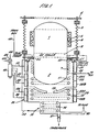
- Fig. 1 shows the overall Stirling engine assembly.
- This comprises a Stirling engine 1 which is mounted in "inverted" configuration, namely with the engine head 2 lowermost.
- the engine is suspended from a plurality of springs 3 attached to a mounting bracket 4 and which surrounds the engine 1. Alternatively it could be suspended from a single centrally located spring.
- An annular absorption mass 5 surrounds the engine and is attached thereto by a plurality of resilient mounts 6 in order to absorb vibrations of the engine.
- the engine head 2 is provided with a plurality of annular fins 7 which absorb heat in a manner to be described thereby heating the engine head.
- the engine also has an engine cooler 8 which is cooled by circulating water again in a manner to be described.
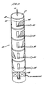
- a heat exchanger is provided by a helical coil 10 which is coaxial with the Stirling engine 1.
- the coil 10 surrounds the bottom end of the head 2 beneath the fins 7, and then extends axially below the engine 1.
- the coil 10 is provided in three distinct stages.
- the first stage 11 surrounds the engine head 2, the second stage 12 is beneath the engine head 2 and is separated therefrom by a baffle 13 which is perforated at its outer periphery.
- the third stage 14 is axially below the second stage 12 and is wound at a smaller radius than the first two stages.
- the third stage 14 is not surrounded by a burner.
- the baffle 13 maintains the temperature and pressure in the first 11 and second 12 stages when the third stage 14 is not firing. Also, heat from the first 11 and second 12 stages is reflected back onto the head 2 of the engine 1.
- the burner 20 has an annular configuration and surrounds the engine head 2 and the coil 10.
- the burner 20 is also divided into stages.
- a first stage 21 surrounds the engine head 2 and annular fins 7.
- a second stage 22 surrounds the lower end of the engine head 2 and the first stage coils 11.
- the third stage 23 of the burner surrounds the second stage coils 12.
- the second 22 and third 23 burner stages are each themselves divided into two sub-stages 22A, 22B, 23A, 23B each of which is independently operable.
- Each of the first burner stage 21, the second sub-stages 22A, 22B and third sub-stages 23A, 23B has a separate supply of air and combustible gas along lines 30, 31, 32, 33 and 34 respectively.
- Each of the stages is also provided with its own ignition system and dedicated ignition control such that each can be ignited independently.
- references are made to "a burner to heat the Stirling engine" and "a supplementary burner”. These two burners can be part of a single multi-stage burner as described with reference to Fig. 1.
- valve 40 The control of the gas and air mixture is achieved by valve 40 as described in more detail in Figs. 2 and 3.
- the valve 40 comprises an inner sleeve 41 and outer sleeve 42.
- the inner 41 and outer 42 sleeves have a pair of orifices 43, 44 of different shapes which are arranged to overlap to differing degrees as the inner 41 and outer 42 sleeves are rotated with respect to one another.
- the flow through each of the lines 30-34 is determined by the degree of overlap of the two orifices.
- a solenoid 45 in the lower end of the housing with the valve 40 provides the relative rotational movement between the inner 41 and outer 42 sleeve.
- the relative sizes of the orifices 43, 44 are arranged to ensure that the flow through each outlet 30-34 is, as closely as possible, a linear function of the rotary position of the inner 41 and outer 42 sleeves.
- FIG. 3 A detailed view of the orifice profiles is given in Fig. 3.
- the hatched areas represent the projection of the orifices 44 onto a flat plane.
- Fig. 3. This shows the positions for which the heat and power output are variable (VAR), maximum (MAX), minimal (MIN), or zero (NONE).
- VAR variable
- MAX maximum
- MIN minimal
- NONE zero
- the operation of the Stirling engine assembly is determined by the domestic demand for electricity and heat. If the demand for electricity is high and the demand for heat is low, the first burner stage 21 and optionally the second burner stage 22 will be fired. Conversely, if the demand for heat is high and the demand for electricity is low, the third burner stage 23 and optionally the second burner stage 22 will be fired. If demand for both electricity and heat is high, all burner stages will be fired. Within these extremes are a number of intermediate settings provided by the various burner stages and sub-stages allowing a high degree of control of the electrical power and heat generation.
- Gas and air for the burners is mixed in a fan/Venturi gas valve arrangement 46 and the speed of the fan can be controlled to vary the overall amount of gas supplied to the various burner stages.
- the position of the inner sleeve 41 of the valve 40 within the outer sleeve 42 is then determined according to the system requirements to ensure the correct supply of gas and air to the various burner stages.
- the gas may be mixed with the air downstream of the valve 40.
- the valve 40 does not have to be sealed to allow pre-mixing.
- it would require a gas/air mixer for each stream from the valve 40.
- Water from the domestic central heating system is fed into the Stirling engine system along line 50 where it first cools the engine cooler 8 and hence absorbs low grade heat. It is then circulated around an annular passage 51 where it cools a seal 52 between the first stage burner 21 and the engine housing.
- one or more cooling channels may feed the water around the outside casing of the burner. These channels may either be in series with or parallel to the passage 51 around the seal 52.
- the water is then fed along line 53 into the supplementary heat exchanger 10. It initially passes around the third stage 14 in which it picks up relatively low grade heat as the third stage is not heated directly by a burner stage. It then circulates up through the helical windings through the second 12 and first 11 windings respectively where it is heated by whichever burner stages are active at the time before finally exiting along line 54 to the domestic central heating system.
- the exhaust gas from the various burner stages exits along flue 60, while condensate from the exhaust gases is drained along condensate drain 61 which is positioned to avoid any dead space where fluid could build up and cause corrosion.
- the heat exchanger coil 10 and burner assembly 20 are mounted directly from the Stirling engine 1 via an annular bracket 55.
- the small residual vibration of the Stirling engine 1 which remains despite the effect of the absorption mass 5 is transmitted to the coils of the supplementary heat exchanger. Any condensation which settles on the coils is encouraged by this vibration to flow along the downwardly angled surfaces of the coil 10 ultimately to the condensate drain 60.
Landscapes
- Engineering & Computer Science (AREA)
- Chemical & Material Sciences (AREA)
- Combustion & Propulsion (AREA)
- Mechanical Engineering (AREA)
- General Engineering & Computer Science (AREA)
- Feeding And Controlling Fuel (AREA)
- Engine Equipment That Uses Special Cycles (AREA)
- Lubrication Of Internal Combustion Engines (AREA)
- Electrically Driven Valve-Operating Means (AREA)
- Air Supply (AREA)
- Control Of Eletrric Generators (AREA)
- Supply And Distribution Of Alternating Current (AREA)
Applications Claiming Priority (3)
| Application Number | Priority Date | Filing Date | Title |
|---|---|---|---|
| GBGB0307283.2A GB0307283D0 (en) | 2003-03-28 | 2003-03-28 | A splitter valve |
| GBGB0316289.8A GB0316289D0 (en) | 2003-03-28 | 2003-07-11 | A combined heat and power system |
| EP04723645A EP1608862B1 (de) | 2003-03-28 | 2004-03-26 | Kraft-wärme-kopplungsanlage |
Related Parent Applications (1)
| Application Number | Title | Priority Date | Filing Date |
|---|---|---|---|
| EP04723645A Division EP1608862B1 (de) | 2003-03-28 | 2004-03-26 | Kraft-wärme-kopplungsanlage |
Publications (2)
| Publication Number | Publication Date |
|---|---|
| EP1887266A2 true EP1887266A2 (de) | 2008-02-13 |
| EP1887266A3 EP1887266A3 (de) | 2008-03-05 |
Family
ID=9955793
Family Applications (1)
| Application Number | Title | Priority Date | Filing Date |
|---|---|---|---|
| EP07021388A Withdrawn EP1887266A3 (de) | 2003-03-28 | 2004-03-26 | Kombiniertes Wärme- und Stromsystem |
Country Status (5)
| Country | Link |
|---|---|
| EP (1) | EP1887266A3 (de) |
| CN (1) | CN100439776C (de) |
| AT (1) | ATE406537T1 (de) |
| DE (1) | DE602004016129D1 (de) |
| GB (2) | GB0307283D0 (de) |
Cited By (4)
| Publication number | Priority date | Publication date | Assignee | Title |
|---|---|---|---|---|
| ITCS20110038A1 (it) * | 2011-12-14 | 2012-03-14 | Ungaro Srl | Stufa a combustione combinata con motore stirling per la produzione di energia elettrica o per pompa di calore |
| GB2485761A (en) * | 2010-10-29 | 2012-05-30 | Tacoma Properties Llc | Micro combined heat and power unit and fuel burner with heat exchange systems |
| US9500191B2 (en) | 2010-01-22 | 2016-11-22 | Ingersoll-Rand Company | Compressor system including a flow and temperature control device |
| US9518579B2 (en) | 2010-01-22 | 2016-12-13 | Ingersoll-Rand Company | Oil flooded compressor having motor operated temperature controlled mixing valve |
Families Citing this family (6)
| Publication number | Priority date | Publication date | Assignee | Title |
|---|---|---|---|---|
| TWI463086B (zh) * | 2011-12-13 | 2014-12-01 | Inventec Corp | 磁力式閥門及應用此磁力式閥門的流體供應管路 |
| DE102013014576A1 (de) * | 2013-09-02 | 2015-03-05 | Mertik Maxitrol Gmbh & Co. Kg | Einrichtung zur Regelung der Verbrennungsluftzufuhr |
| CN108591536B (zh) * | 2018-05-08 | 2023-11-14 | 上海焦耳波动节能环保科技有限公司 | 一种机械式安全阀 |
| CN109458511B (zh) * | 2018-09-28 | 2020-09-25 | 中国辐射防护研究院 | 一种使用气流调节器的分配调节器 |
| CN113531160A (zh) * | 2021-06-25 | 2021-10-22 | 机械工业第九设计研究院有限公司 | 一种双向旋转输蜡阀 |
| CN115875480B (zh) * | 2022-11-22 | 2025-10-03 | 佛山市顺德区精睿电子有限公司 | 一种流量调节阀及流量调节系统 |
Family Cites Families (9)
| Publication number | Priority date | Publication date | Assignee | Title |
|---|---|---|---|---|
| FR1293654A (fr) * | 1961-04-07 | 1962-05-18 | Snecma | Dispositif de distribution de fluide applicable notamment à la gouverne par jet desavions à décollage vertical |
| DE3941040A1 (de) * | 1988-12-24 | 1990-06-28 | Siemens Ag | Regulierventil mit einem einen durchlasskanal aufweisenden drehkolben |
| DE4117445C2 (de) * | 1991-05-28 | 1994-10-06 | Gastechnic Prod Vertriebges | Ventil zum Steuern oder Regeln des Durchflusses eines Strömungsmittels |
| US6113483A (en) * | 1999-02-17 | 2000-09-05 | Daimlerchrysler Corporation | Variable mode air distribution system |
| DE19936591C1 (de) * | 1999-08-04 | 2001-02-15 | Bosch Gmbh Robert | Gasbetriebene Generator-Therme |
| DE19943613B4 (de) * | 1999-09-11 | 2006-09-07 | Robert Bosch Gmbh | Heizsystem zur Wärme- und Stromerzeugung |
| NL1015319C2 (nl) * | 2000-05-26 | 2001-11-27 | Enatec Micro Cogen B V | Inrichting en werkwijze voor het gekoppeld opwekken van warmte en elektriciteit. |
| GB2365519B (en) * | 2000-08-04 | 2005-03-09 | Llanelli Radiators Ltd | Air distribution apparatus for a vehicular air conditioning system |
| GB0124985D0 (en) * | 2001-10-17 | 2001-12-05 | Bg Intellectual Pty Ltd | A heat fan assembly and method of controlling a fan |
-
2003
- 2003-03-28 GB GBGB0307283.2A patent/GB0307283D0/en not_active Ceased
- 2003-07-11 GB GBGB0316289.8A patent/GB0316289D0/en not_active Ceased
-
2004
- 2004-03-26 DE DE602004016129T patent/DE602004016129D1/de not_active Expired - Lifetime
- 2004-03-26 EP EP07021388A patent/EP1887266A3/de not_active Withdrawn
- 2004-03-26 CN CNB2004800076289A patent/CN100439776C/zh not_active Expired - Fee Related
- 2004-03-26 AT AT04723644T patent/ATE406537T1/de not_active IP Right Cessation
Cited By (5)
| Publication number | Priority date | Publication date | Assignee | Title |
|---|---|---|---|---|
| US9500191B2 (en) | 2010-01-22 | 2016-11-22 | Ingersoll-Rand Company | Compressor system including a flow and temperature control device |
| US9518579B2 (en) | 2010-01-22 | 2016-12-13 | Ingersoll-Rand Company | Oil flooded compressor having motor operated temperature controlled mixing valve |
| GB2485761A (en) * | 2010-10-29 | 2012-05-30 | Tacoma Properties Llc | Micro combined heat and power unit and fuel burner with heat exchange systems |
| ITCS20110038A1 (it) * | 2011-12-14 | 2012-03-14 | Ungaro Srl | Stufa a combustione combinata con motore stirling per la produzione di energia elettrica o per pompa di calore |
| WO2013087814A3 (en) * | 2011-12-14 | 2013-08-08 | Ungaro Srl | Burning stove combined with a stirling engine for producing electricity or to be coupled to a heat pump |
Also Published As
| Publication number | Publication date |
|---|---|
| CN100439776C (zh) | 2008-12-03 |
| ATE406537T1 (de) | 2008-09-15 |
| GB0307283D0 (en) | 2003-05-07 |
| GB0316289D0 (en) | 2003-08-13 |
| EP1887266A3 (de) | 2008-03-05 |
| CN1761829A (zh) | 2006-04-19 |
| DE602004016129D1 (de) | 2008-10-09 |
Similar Documents
| Publication | Publication Date | Title |
|---|---|---|
| EP1608862B1 (de) | Kraft-wärme-kopplungsanlage | |
| EP1887266A2 (de) | Kombiniertes Wärme- und Stromsystem | |
| JP2005530121A (ja) | 加熱装置 | |
| JP2009542952A (ja) | 家庭用熱電併給システム | |
| WO2019028176A1 (en) | WATER HEATER | |
| EP0018988A1 (de) | Verfahren und vorrichtung zum verbessern des wärmetransports | |
| US7650750B2 (en) | Domestic combined heat and power assembly | |
| EP1481155B1 (de) | Stirling-Motor einschließend Rekuperatorhitzer | |
| CN101292082A (zh) | 热电联产系统 | |
| JP2007503550A (ja) | 加熱装置 | |
| GB2520845A (en) | Micro combined heat and power unit | |
| RU2181163C1 (ru) | Газотурбинная установка | |
| JP2009542951A (ja) | スターリングエンジンアセンブリ | |
| US12318727B2 (en) | System and method for controlling a temperature in an absorber | |
| GB2534298A (en) | Micro combined heat and power unit | |
| HK1031759A (en) | A water heating system | |
| WO2009022207A2 (en) | Combined heat and power system |
Legal Events
| Date | Code | Title | Description |
|---|---|---|---|
| PUAI | Public reference made under article 153(3) epc to a published international application that has entered the european phase |
Free format text: ORIGINAL CODE: 0009012 |
|
| PUAL | Search report despatched |
Free format text: ORIGINAL CODE: 0009013 |
|
| 17P | Request for examination filed |
Effective date: 20071102 |
|
| AC | Divisional application: reference to earlier application |
Ref document number: 1608862 Country of ref document: EP Kind code of ref document: P |
|
| AK | Designated contracting states |
Kind code of ref document: A2 Designated state(s): AT BE BG CH CY CZ DE DK EE ES FI FR GB GR HU IE IT LI LU MC NL PL PT RO SE SI SK TR |
|
| AK | Designated contracting states |
Kind code of ref document: A3 Designated state(s): AT BE BG CH CY CZ DE DK EE ES FI FR GB GR HU IE IT LI LU MC NL PL PT RO SE SI SK TR |
|
| RIC1 | Information provided on ipc code assigned before grant |
Ipc: F02G 1/043 20060101AFI20080131BHEP Ipc: F02G 1/047 20060101ALI20080131BHEP |
|
| AKX | Designation fees paid |
Designated state(s): AT BE BG CH CY CZ DE DK EE ES FI FR GB GR HU IE IT LI LU MC NL PL PT RO SE SI SK TR |
|
| STAA | Information on the status of an ep patent application or granted ep patent |
Free format text: STATUS: THE APPLICATION IS DEEMED TO BE WITHDRAWN |
|
| 18D | Application deemed to be withdrawn |
Effective date: 20080906 |