EP1887687A1 - Vorrichtung und Methode zur Kompensation in akustischen Systemen - Google Patents
Vorrichtung und Methode zur Kompensation in akustischen Systemen Download PDFInfo
- Publication number
- EP1887687A1 EP1887687A1 EP06016049A EP06016049A EP1887687A1 EP 1887687 A1 EP1887687 A1 EP 1887687A1 EP 06016049 A EP06016049 A EP 06016049A EP 06016049 A EP06016049 A EP 06016049A EP 1887687 A1 EP1887687 A1 EP 1887687A1
- Authority
- EP
- European Patent Office
- Prior art keywords
- sound
- impedance
- sound output
- output device
- frequency
- Prior art date
- Legal status (The legal status is an assumption and is not a legal conclusion. Google has not performed a legal analysis and makes no representation as to the accuracy of the status listed.)
- Withdrawn
Links
Images



Classifications
-
- H—ELECTRICITY
- H03—ELECTRONIC CIRCUITRY
- H03G—CONTROL OF AMPLIFICATION
- H03G5/00—Tone control or bandwidth control in amplifiers
- H03G5/02—Manually-operated control
- H03G5/025—Equalizers; Volume or gain control in limited frequency bands
-
- H—ELECTRICITY
- H04—ELECTRIC COMMUNICATION TECHNIQUE
- H04R—LOUDSPEAKERS, MICROPHONES, GRAMOPHONE PICK-UPS OR LIKE ACOUSTIC ELECTROMECHANICAL TRANSDUCERS; ELECTRIC HEARING AIDS; PUBLIC ADDRESS SYSTEMS
- H04R29/00—Monitoring arrangements; Testing arrangements
- H04R29/001—Monitoring arrangements; Testing arrangements for loudspeakers
-
- H—ELECTRICITY
- H04—ELECTRIC COMMUNICATION TECHNIQUE
- H04R—LOUDSPEAKERS, MICROPHONES, GRAMOPHONE PICK-UPS OR LIKE ACOUSTIC ELECTROMECHANICAL TRANSDUCERS; ELECTRIC HEARING AIDS; PUBLIC ADDRESS SYSTEMS
- H04R3/00—Circuits for transducers
- H04R3/04—Circuits for transducers for correcting frequency response
Definitions
- the present invention is directed to a device and methods for frequency response characteristics compensation of acoustical systems by determined frequency dependent impedances.
- the present invention relates to a method and device for power compensation for acoustical systems by using impedance information of the system, thereby establishing high fidelity sound, solving safety problems for the system, providing dynamic speaker compensation, etc.
- This method can be applicable on every multimedia consumer and professional grade electronic product which uses a sound output device.
- the main problem for acoustical systems is the frequency response characteristics of sound output devices because sound output devices do not have the same characteristics for every frequency.
- the changing impedance in the system causes imparted sound quality, unreliability and safety problems. Compensation must be established to get over these problems.
- One of the main parameters in sound quality of multimedia devices - like audio reproduction systems - is the frequency response characteristics.
- a person can, depending on age, realize an audio frequency range between 20 Hz and 22 kHz.
- a sound reproduction device is expected to provide this frequency range.
- the assessment of this performance criterion is made by acustical test devices and an analysis in the frequency domain, as shown below.
- the efficiency of the audio device is accepted to be the frequency range.
- the SPL sound pressure level
- a ⁇ 3 dB change in the SPL is accepted to be the limits of the working frequency range (Some standards take these values as ⁇ 5 dB). These frequencies are the high cut-off frequency and the low cut-off frequencies of the system. Acoustical compensation is the process for fixing the cut-off frequencies of the devices.
- Frequency based acoustical performance improvements are generally achieved by bandpass filters on sound processors or analogue bandpass filters (equalizers) where the system does not include sound processors and/or general purpose processors.
- the impedance of the speaker changes with the frequency.
- the speaker generally needs to be driven by a changeable current to have a stable power for every frequency.
- the frequency response characteristics of the speaker changes with the acoustical structure of the system. So, upon modifying the system, it needs to be tested again as it will have a different frequency response characteristic.
- Equalizers operate at certain frequencies. That means, it is not possible to totally control the frequency domain as equalizers do not include a filter for every frequency. As mentioned above, characteristics of each sound output device are unique and for best performance, the exact frequency should be compensated. Also, the compensation is made by considering the processed output signal. That means, there is no control of the output device. This may cause safety problem as the current through the output device is not controlled.
- RLC circuits provide impedance compensation at the output device for certain frequencies. They are designed for the general frequency response of that sound output device type. They cannot be redesigned for every system throughout manufacturing. Also the difference between the impedances of a sound output device can attain high values. In that situation an RLC circuit may not be capable of compensating the impedance of the output.
- Every sound output device has a unique frequency response characteristic. Any difference that may be caused due to the tolerance of the elements used in the manufacturing of the device or the assembling of the sound output device causes the frequency response to change. So, every sound system has to be tested and adjusted for the best performance individually. It is not applicable to serial production of most of the products.
- Compensation methods that are conducted by using the audio output signal are not capable of considering the characteristics of the sound output devices. That means, the compensation is done, due to the output signal. Audio signals cannot be effected if the output device has high impedance values in that frequency. I.e., some sound output devices cannot correctly output the audio data as an. This causes degradation in audio quality at the frequency concerned. Also the harmonics of that signal can be responsible for generating noise at other frequencies. In other words, those systems are not capable of controlling the noise that is caused by the structure of the output device.
- Equalizers have certain frequency compensation limits and cannot be calibrated perfectly for every sound output device.
- the basic principle of the invention resides in the provision of a mechanism which compensates frequency components of an input signal in a way that the different impedances the output device (speaker, headphone) exhibits at these frequencies, are "levelled” or compensated.
- the invention is in a first aspect directed to a device for frequency response characteristics compensation of acoustical systems which comprises at least one sound output device; a frequency generator for generating a plurality of test signals of different effective test frequencies to be applied to the sound output device; an impedance measuring device connected to the sound output device for determining the impedance of the sound output device for each of the plurality of test signals applied to the sound output device; a memory unit for storing frequency response characteristics compensation information for each test frequency, in accordance with the impedance determined for the test signal of each test frequency; and a sound processing device for generating acoustical signals to be output to the sound output device, based on input signals, which are power-compensated according to their respective frequency components and said compensation information, to thereby compensate for differences in the impedance of said sound output device at different output frequencies.
- the device according to the invention further comprises an amplifier coupled between the sound processing device and the sound output device for amplifying the acoustical signal.
- This amplifier may e.g. be employed if a speaker or speaker system is to be driven by the output of the device.
- the sound processing device is configured to adjust input signal components of different frequencies having equal input power so as to generate acoustical signals resulting in equal power for the respective frequencies at the sound output device.
- the power may be the electrical power in the sound output device, or the sound pressure level of the device, etc.
- the device may further be characterised in that the frequency generator is connected to the sound processing device, for outputting the test signals to the sound output device via the sound processing device.
- the device further comprises a calculating unit connected to the impedance measuring device and to the memory unit, which is used for determining the compensation information according to the measured impedance and a preset algorithm, or/and for calculating the impedance from other values obtained by the impedance measuring device, and for storing said compensation information in the memory unit.
- a calculating unit connected to the impedance measuring device and to the memory unit, which is used for determining the compensation information according to the measured impedance and a preset algorithm, or/and for calculating the impedance from other values obtained by the impedance measuring device, and for storing said compensation information in the memory unit.
- the sound processing device may perform the two tasks of performing a power compensation of the input signal, and of performing further processing known in the art of sound processing, like e.g. filtering, amplitude adjustment or frequency push up/down.
- the sound processing device may comprise a sound processor for performing these tasks of adjusting electrical characteristics of the input signals according to preset rules, and of compensating for differences in the impedance of said sound output device at different output frequencies, according to said compensation information.
- a sound processor is an "off the shelf" product which has the advantage of being cheap and well known to programmers. Often, there are standard programs for performing some of the basic tasks of sound processing, which may be used in the present invention.
- Some sound processors comprise frequency generators. Accordingly, in one preferred embodiment of the invention, the frequency generator may be a part of the sound processor.
- the integration of the two functions allows for a smoother integration and will lower production cost.
- the sound processor may also comprise prescale blocks configured for said compensation of the input signals for said differences in the impedance of said sound output device at different output frequencies, according to said compensation information, and common compensation blocks arranged after the prescale blocks configured for adjusting said electrical characteristics of the input signals according to the preset rules.
- the sound processing device comprises a microprocessor for compensating the input signals for said differences in the impedance of said sound output device at different output frequencies, according to said compensation information, a sound processor for adjusting electrical characteristics of the input signals compensated at the microprocessor, according to preset rules, and a connection between the microprocessor and the sound processor for supplying the input signal to the microprocessor and for supplying the compensated input signals back to the sound processor.
- the sound processing device may comprise a microprocessor or a microcontroller for calculating compensation instructions for compensating differences in the impedance of said sound output device at different output frequencies, according to said compensation information, a connection between the microprocessor and a sound processor and said sound processor for adjusting electrical characteristics of the input signals according to preset rules, and for compensating said differences in the impedance of said sound output device at different output frequencies, according to said compensation instructions received via the connection.
- microprocessor in the following, as well as the claims, the term microprocessor will be used as comprising microprocessors as well as microcontrollers. It is to be understood that a microcontroller comprises a microprocessor and additional components, like e.g. memory, input/output ports, further controllers for hardware devices etc.) may at the same time also take the function of the above-mentioned calculating unit which is connected to the impedance measuring device and to the memory unit, for determining said compensation information according to the measured impedance and a preset algorithm, and for storing said compensation information in the memory unit.
- additional components like e.g. memory, input/output ports, further controllers for hardware devices etc.
- the memory unit may be part of the microprocessor, or the signal processor, or may be a separate device.
- the sound output device may be any of a number of known devices for generating sound waves.
- the sound output device may for example comprise a headphone or a speaker or a set of speakers.
- the compensation information determined/calculated may take several kinds.
- the compensation information may preferably be the determined impedance for each frequency, or may be a correction factor for the determined impedance for each frequency. Storing the impedances as such requires less calculation when the measurements are performed, but will require more real time calculations when the compensation is done while operating the sound device. Conversely, using a correction factor will require more calculations when the impedance is measured, but may simplify the determination of the compensation to be performed on an input signal in operating the device.
- the quality of the compensation according to the present invention will inter alia be determined by the number and location in the frequency spectrum of the analysed frequencies.
- the minimum number of frequencies, for which impedances are determined, will be two. The more frequencies are measured and compensated, the better should be the result of the power compensation; but the more measurements and calculations are required.
- the plurality of test signals have equally spaced frequencies.
- the plurality of test signals have predetermined frequencies.
- test signals may take any suitable signal shape.
- the test signals are sinoidal signals.
- the frequency generator Preferably, there is some kind of synchronisation between the frequency generator and the remaining parts of the measuring system, in order to assure that the impedance measurements are correlated and stored with the right one of the frequencies.
- the invention is in another aspect directed to methods. Everything that was said with regard to the device does likewise apply to the methods and vice versa, so that mutual reference is made.
- One aspect of the invention is a method for performing frequency response characteristics compensation of acoustical systems, and comprises the steps:
- the method is preferably performed when the sound output device is first operated after its manufacturing. This will set the required compensation values for each individual sound output device, in order to compensate individual differences of such devices caused by manufacturing deviations.
- the method is in another preferred embodiment performed each time the sound output device is initialised.
- the method may also be performed periodically or manually.
- the acoustical system comprises a plurality of sound output devices, for example two stereo speakers, and the method is performed for every sound output device (or a specified sub set of sound output devices) of the acoustical system.
- the method comprises the further step of modifying each frequency component of an acoustical signal in response to the frequency response characteristics compensation information for the frequency of said component.
- the method according to the invention may be characterised in that the compensation information is the determined impedance for each frequency or is a correction factor for the determined impedance for each frequency.
- Output acoustical signals are preferably power-compensated according to their respective frequency components and said compensation information, to thereby compensate for differences in the impedance of said sound output device at different output frequencies.
- the compensation is achieved by adjusting the currents of the signal components.
- the invention is further directed to a method of operating a sound device, comprising the steps:
- the method also covers the usual operation of the device after or between the calibration of the compensation.
- the method may, as the calibrating step, in particular include the method of performing frequency response characteristics compensation according to the invention.
- the invention is in yet another aspect directed to a manufacturing process for sound appliances, which comprise a system according to the invention, and at least one sound output device, which method comprises:
- the basic principle of the invention resides in the provision of a mechanism which compensates frequency components of an input signal in a way that the different impedances the output device (speaker, headphone) exhibits at these frequencies, are "levelled” or compensated.
- the invention is in a first aspect directed to a device for frequency response characteristics compensation of acoustical systems which comprises at least one sound output device; a frequency generator for generating a plurality of test signals of different effective test frequencies to be applied to the sound output device; an impedance measuring device connected to the sound output device for determining the impedance of the sound output device for each of the plurality of test signals applied to the sound output device; a memory unit for storing frequency response characteristics compensation information for each test frequency, in accordance with the impedance determined for the test signal of each test frequency; and a sound processing device for generating acoustical signals to be output to the sound output device, based on input signals, which are power-compensated according to their respective frequency components and said compensation information, to thereby compensate for differences in the impedance of said sound output device at different output frequencies.
- a frequency generator is an electronic device capable of generating electrical signals having specific frequencies; in the invention, it is preferred that the frequency generator can generate several signals of different frequencies, covering part of or the entire frequency range that either the sound output device is able to output, or the input signal may have.
- the term "effective test frequency" refers to the fact that the frequency generator may generate rather diverse signals, including sinus signals, sawtooth signal or complex signals constituted by several basic signals. The effective frequency means the frequency at which these signals act upon the sound output device.
- the test signal which is used as a signal applied to the sound output device is one of several test signals used each having a single, determined test frequency.
- An input signal is an electrical signal entering the device of the invention through one or several input interfaces, as known to the skilled person in the field of designing audio devices. It represents acoustical information which will be processed by the sound processing device to produce an acoustical signal to be output at the sound output device.
- the input signal normally consists of numerous different frequency components which together may represent music or speech.
- the sound processing device processes the input signal's frequency components by applying the frequency response characteristics compensation information to the respective frequency components of the input signal. The processing is performed via e.g. an algorithm implemented in the sound processing device, in order to achieve a power compensation of the signals.
- Power compensation means that the power of the output acoustical signal, when applied to the sound output device, achieves a predetermined absolute or relative value, which is inter alia determined by the impedance of the sound output device at that frequency.
- the sound pressure level may be used as a reference for compensating the acoustical signal.
- a correlating algorithm must be implemented in order to relate the measured impedance with the sound pressure level. Therefore, an additional measure of the sound pressure characteristics of the sound output device needs to be made.
- the power may for example be compensated by using a gain coefficient for the signal amplitude.
- the processing may further include usual, known processing of the input signal, in order to prepare it for output.
- An acoustical signal is an electrical signal capable of being output as sound waves at a sound output device. It may be a signal which needs further amplification, or may directly be output, depending on the type of sound output device. In the present invention, the acoustical signal is the output signal of the sound processing device.
- the frequency response characteristics compensation information is some kind of information derived from the frequency of the test signals and the impedances determined for said frequencies, and is or comprises information which is suitable to be used for power compensation of an input signal processed at the sound processing device.
- a sound output device is any kind of device which translates electrical signals into audible sound waves.
- the device comprises at least one sound output device. It is to be understood however that several sound output devices may be implemented in a device according to the invention, and each of these sound output devices may be compensated individually, based on frequency response characteristics compensation information derived for each sound output device. Accordingly, either several frequency generators, impedance measuring devices, memory units and sound processing devices may be used, or one of these devices, respectively, may be shared among the sound output devices. A typical number of sound output devices will be two for Stereo systems, and five for surround sound systems.
- the impedance measuring device may be any device for determining an impedance or other values relating to the impedance, like current and/or voltage, of a circuit. Such devices are known in the art. It may be connected in parallel or serially with the sound output device. In a further preferred embodiment, there may additionally be provided a switchable circumventing connection line in order for the acoustical signal to circumvent the impedance measuring device when no impedance measuring is performed (e.g. in normal operating conditions, where an acoustical signal is output at the sound output device).
- the memory unit may be any known device/circuit for storing the necessary information, for example a RAM, EPROM, Flash Memory etc. It may also be an analogue device for storing this information.
- the memory unit may also be part of another device of the inventive device, like a sound processor, a microprocessor, or even the impedance measuring unit.
- the device according to the invention further comprises an amplifier coupled between the sound processing device and the sound output device for amplifying the acoustical signal.
- the sound processing device is configured to adjust input signal components of different frequencies having equal input power so as to generate acoustical signals resulting in equal power for the respective frequencies at the sound output device.
- the power may be the electrical power in the sound output device, or the sound pressure level of the device, etc.
- the device may further be characterised in that the frequency generator is connected to the sound processing device, for outputting the test signals to the sound output device via the sound processing device.
- the frequency generator may also be directly connected with the amplifier or the sound output device.
- the device further comprises a calculating unit connected to the impedance measuring device and to the memory unit, which is used for determining the compensation information according to the measured impedance and a preset algorithm, or/and for calculating the impedance from other values obtained by the impedance measuring device, and for storing said compensation information in the memory unit.
- the calculating unit may be any device known to the skilled person as being able to perform its task, e.g. a hardware circuit with a built-in algorithm or a programmable device.
- the calculating unit may merely be a device for converting the measured impedance values to digital representations thereof, e.g. an A/D converter, and for sending the digital representations to the memory unit, which after having received the digital representations, stores them in memory cells.
- the sound processing device may perform the two tasks of performing a power compensation of the input signal, and of performing further processing known in the art of sound processing, like e.g. filtering, amplitude adjustment or frequency push up/down.
- the sound processing device may comprise a sound processor for performing these tasks of adjusting electrical characteristics of the input signals according to preset rules, and of compensating for differences in the impedance of said sound output device at different output frequencies, according to said compensation information.
- a sound processor is a device in general well known to skilled persons. E.g. a digital signal processor (DSP) may be used to perform this task.
- DSP digital signal processor
- Some sound processors comprise frequency generators. Accordingly, in one preferred embodiment of the invention, the frequency generator may be a part of the sound processor.
- the sound processor may also comprise prescale blocks configured for said compensation of the input signals for said differences in the impedance of said sound output device at different output frequencies, according to said compensation information, and common compensation blocks arranged after the prescale blocks configured for adjusting said electrical characteristics of the input signals according to the preset rules.
- prescale blocks of the sound processor may be used for compensating the input signals, or special input blocks may be provided in the sound processor for performing this task.
- Prescale blocks are generally known to skilled persons, but have not been applied for power compensation.
- the sound processing device comprises a microprocessor for compensating the input signals for said differences in the impedance of said sound output device at different output frequencies, according to said compensation information, a sound processor for adjusting electrical characteristics of the input signals compensated at the microprocessor, according to preset rules, and a connection between the microprocessor and the sound processor for supplying the input signal to the microprocessor and for supplying the compensated input signals back to the sound processor.
- the compensation is not done in the sound processor (if one is provided), but in a general purpose microprocessor, thus removing processing load from the sound processor.
- the sound processing device may comprise a microprocessor for calculating compensation instructions for compensating differences in the impedance of said sound output device at different output frequencies, according to said compensation information, a connection between the microprocessor and a sound processor and said sound processor for adjusting electrical characteristics of the input acoustical signals according to preset rules, and for compensating said differences in the impedance of said sound output device at different output frequencies, according to said compensation instructions received via the connection.
- a connection between the microprocessor and a sound processor and said sound processor for adjusting electrical characteristics of the input acoustical signals according to preset rules, and for compensating said differences in the impedance of said sound output device at different output frequencies, according to said compensation instructions received via the connection.
- an additional microprocessor is used instead of the sound processor itself, to calculate the required power compensation. The result of the calculation is used to control the sound processor, e.g. by sending correction information.
- only part of the compensation of the input signals is performed by a microprocessor, while another part is done by the
- the microprocessor may at the same time also take the function of the above-mentioned calculating unit which is connected to the impedance measuring device and to the memory unit, for determining said compensation information according to the measured impedance and a preset algorithm, and for storing said compensation information in the memory unit.
- the memory unit may be part of the microprocessor, or the signal processor, or may be a separate device.
- the sound output device may be any of a number of known devices for generating sound waves.
- the sound output device may for example comprise a headphone or a speaker or a set of speakers.
- the compensation information determined/calculated may take several kinds.
- the compensation information may simply be the determined impedance for each frequency, or may be a correction factor for the determined impedance for each frequency. Storing the impedances as such requires less calculation when the measurements are performed, but will require more real time calculations when the compensation is done while operating the sound device. Conversely, using a correction factor will require more calculations when the impedance is measured, but may simplify the determination of the compensation to be performed on an input signal in operating the device.
- the correction factor may e.g. be a factor with which a signal level or voltage etc. of the input signal is to be multiplied by.
- the quality of the compensation according to the present invention will inter alia be determined by the number and location in the frequency spectrum of the analysed frequencies.
- the minimum number of frequencies, for which impedances are determined, will be two. The more frequencies are measured and compensated, the better should be the result of the power compensation; but the more measurements and calculations are required.
- the plurality of test signals have equally spaced frequencies. Starting from a "base" frequency, the other test frequencies are determined by adding or subtracting a frequency (Hz amount). Alternatively, the plurality of test signals have predetermined frequencies.
- test signals may take any suitable signal shape.
- the test signals are sinoidal signals.
- the frequency generator Preferably, there is some kind of synchronisation between the frequency generator and the remaining parts of the measuring system, in order to assure that the impedance measurements are correlated and stored with the right one of the frequencies.
- the invention is in another aspect directed to methods. Everything that was said with regard to the device does likewise apply to the methods and vice versa, so that mutual reference is made.
- the method according to the invention is for performing frequency response characteristics compensation of acoustical systems, and comprises the steps:
- the method is preferably performed when the sound output device is first operated after its manufacturing. This will set the required compensation values for each individual sound output device, in order to compensate individual differences of such devices caused by manufacturing deviations.
- the method is in another preferred embodiment performed each time the sound output device is initialised.
- the method may also be performed periodically or manually.
- the acoustical system comprises a plurality of sound output devices, for example two stereo speakers, and the method is performed for every sound output device (or a specified sub set of speakers) of the acoustical system.
- the method comprises the further step of modifying each frequency component of an acoustical signal in response to the frequency response characteristics compensation information for the frequency of said component.
- the method according to the invention may be characterised in that the compensation information is the determined impedance for each frequency or is a correction factor for the determined impedance for each frequency.
- Output acoustical signals are preferably power-compensated according to their respective frequency components and said compensation information, to thereby compensate for differences in the impedance of said sound output device at different output frequencies.
- the compensation is achieved by adjusting the currents of the signal components.
- the invention is further directed to a method of operating a sound device, comprising the steps:
- the method also covers the usual operation of the device after or between the calibration of the compensation.
- the method may, as the calibrating step, in particular include the calibration method of the invention.
- the invention is furthermore directed to a manufacturing process for sound appliances, which comprise a system according to the invention, and at least one sound output device, which method comprises:
- This method allows for the "matching" or “pairing” of sound output devices with the controlling electronics, in order to take account of production variance in the manufacture of such sound output devices.
- one or several particular sound output devices, like speakers, of some batch of sound output devices are used for assembling one particular sound appliance.
- a sound appliance is any device or separate or separable entity used for listening to sound like music or speech.
- the present invention relates to a method for power compensation for acoustical systems by using impedance information of the system, thereby establishing high fidelity sound, solving safety problems for the system, providing dynamic speaker compensation, etc.
- This method can be applicable on every multimedia consumer electronic product which uses a sound output device.
- the system realises the impedance & frequency characteristics of the sound output device; stores these characteristics; and uses them in compensation.
- the main idea of the invention is processing the audio input signal by reference of the impedance & frequency characteristics of the sound output device.
- the speaker impedance is depending on the frequency and the acoustical structure of the sound output device. So, there is a problem to get a stable output power performance for every frequency or a great frequency range with sufficiently small iterations in frequency, in acoustical systems. This causes loss in sound quality and safety problems, etc.
- the impedance & frequency characteristics of the sound output device is determined, stored and used in compensation.
- the frequency response characteristics of the system are idealized; a high fidelity sound is established; current on the sound output device is controlled and safety problem is solved; and dynamic speaker compensation is provided.
- the system of the embodiment shown in Fig. 2 consists of six main blocks. These are; an impedance sensor 21, microprocessor 32, signal generator (frequency generator) 35, sound processor 31, coefficient table (memory unit) 33 of the algorithm and changeable total system impedance shown at 25.
- the sound output system 20 consists of a chassis 12 and the speaker 11 itself. Furthermore, an amplifier 40 is provided.
- the device includes a impedance line for connecting the impedance sensor 21 with the microprocessor 32, a gain feedback line 37 for connecting the microprocessor 32 with the sound processor 31, an input line 38 for supplying the sound processor 31 with input signals, and an audio line 36 for transferring the processed acoustical signal from sound processor 31 to the amplifier 40.
- a by-pass including a switch 22 is used to by-pass or circumvent the impedance sensor 21 when no impedance measurements are to be performed.
- the frequency generator 35 is responsible for generating (audio) test signals that are used to determine the impedance & frequency characteristics of the system and should be activated at least in installation and when the sound output device 10 of the system is changed.
- the frequency of the generated signal and the impedance of the sound output device 10 in that frequency are stored in the coefficient table 33 as the impedance & frequency characteristics data of the system.
- the frequency generator 35 can be included in the sound processor 31 or the microprocessor 32.
- the system determines the frequency response characteristics only if that frequency is generated by the generator.
- Some sound processors 31 include frequency generators 35. In those systems there is no use for having an outer generator block in the system.
- the impedance sensor device 21 determines the characteristic data that can be voltage, current or impedance for that frequency and sends it to the coefficient table of the algorithm.
- Current prop, low power consuming ohmic resistance, magnetic field sensor or any electronic component that is capable of determining current or voltage or impedance can be used as impedance sensor. As different sensors have different properties, it may be in series or parallel to the system. The appropriate impedance sensor for every system may vary.
- the impedance sensor may be by-passed if there will be no change in the impedance & frequency characteristics of the sound output device.
- the frequency of the generated signal and the frequency response of the system for that frequency are stored in the coefficient table of the algorithm 33.
- the coefficient table consists of - full scale (if possible) - impedance & frequency coefficients and any coefficient related to frequency response in order to base frequency impedance response of the system.
- the frequency values in the coefficient table 33 can changed if another signal generator 35 is used to determine the frequency response of the sound output device 10. Also, the frequency response of the sound output device 10 can change if another signal generator 35 is used to determine the frequency response.
- Any read/write memory device can be used to store the coefficient table.
- memory device can be a separate memory device or be included by micro controller or sound processor.
- the microprocessor 32 is responsible for sound processing for compensation.
- the microprocessor gets the impedance & frequency characteristics data of the system from the coefficient table 33 and compensates the input audio signal.
- That compensation includes any sound processing including filtering, amplitude adjustment or frequency push up / down.
- the main idea of the compensation is signal processing before the common blocks of sound processing. Sound processing before the common sound processing blocks has lots of advantages like lower noise ratio and power reduction.
- the sound processing for compensation can be done in the microprocessor or prescale blocks of the sound processor. By this method, the disadvantages of the common equalization are avoided.
- the performance of the sound output device is maximized, the current on the output device can be controlled, most of the reasons of sound quality loss like Doppler effect at the output signal is avoided.
- the microprocessor 32 may be included by the sound processor 31 to form a complete sound processing device 30.
- the sound processor 31 is responsible for frequency analysis of the audio input signal by referencing the data in the coefficient table 33.
- the analysed signal is compensated in the microprocessor 32.
- the changeable total system impedance can be simulated as a circuit 25. That block is used to have a reference value for the impedance & frequency response characteristics of the sound output device.
- Gain feedback line 37 and audio line 36 can be moved into the sound processor 31 if related blocks can be included by the sound processor 31.
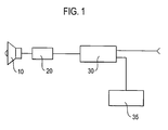
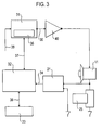
- Fig. 3 shows a further embodiment of the present invention. Like reference numerals are used to indicate like features as in Figs. 1 and 2.
- FIG. 3 illustrates the general circuit diagram a further embodiment of the invention including the main components.
- signals generated by generator 35 which can be a separate component or be included in microprocessor 32 or sound processor 31 is used to determine the frequency response of the system at that frequency.
- Impedance response characteristics are stored in the coefficient table 33 shown as a separate device in this embodiment.
- the data in the coefficient table include impedance coefficients for every frequency that can be generated and other compensation coefficients that can be determined or calculated by the inventive device and method.
- Stored data is used to compensate the unprocessed audio input signal in the microprocessor.
- the compensated audio input signal can be processed in sound processor and is directed to the amplifier.
- the compensated, processed and amplified audio signal is received by the sound output device 11.
- Fig. 4 depicts a preferred embodiment of the method according to the invention.
- a calibration mode of the device is activated. This may comprise switching on the impedance measuring device 21, activating and setting the frequency generator, loading a program for analysing the measured impedance/voltage/current values into a microprocessor, etc.
- a test signal of a specified, predetermined frequency is generated and output/applied to the sound output device 10, by the frequency generator 35.
- the impedance is determined for the applied frequencies by the impedance measuring device 21, possibly in connection with a calculating unit.
- step S13 a compensation information for said frequency is calculated, based on some preset algorithm, and the impedance determined in step S12. This compensation information is stored in step S14 in a memory unit, together with some reference to the frequency which is presently assessed. After this, it is judged in step S15 if more frequencies are to be tested. If this is the case, the processing returns to step S11. If no more impedances of further frequencies need to be determined, and the calibration is hence completed, the processing proceeds to step S16, in which a "compensation" or normal operating mode is activated, while the calibration mode is terminated.
- Fig. 5 depicts a further preferred embodiment of the method according to the invention.
- the "compensation" mode mentioned in Fig. 5 is shown, which uses the compensation information obtained in the process outlined in e.g. Fig. 4.
- step S16 identical to step 16 of Fig. 4
- the compensation mode is activated.
- step S17 an input signal representing some kind of acoustical information is read into the sound processing device.
- step S18 the input signal is decomposed into frequency components, to which a compensation is to be applied. It is to be understood that other approaches for compensation may be used, as long as a frequency specific compensation for differences in the impedance is possible with the respective frequency components of the input signal.
- step S19 the compensation itself is performed on the frequency components of the input signal, using e.g. a sound processor, a microprocessor, some suitable algorithm and the compensation information. This results in compensated input signal frequency components, which may optionally be further processed in known manner to improve the signal, in step S20.
- step S21 the compensated frequency components are recomposed, in order to give a compensated output acoustical signal. If a digital input signal is used, a digital/analogue conversion must additionally be performed at some step of the method, preferably after the compensation is done.
- the present invention has obvious advantages in acoustical compensation as the compensation is achieved by using determined and stored impedance & frequency characteristics of the system in a separate microprocessor or in prescale block of a sound processor before the common compensation blocks. These advantages include: high fidelity sound at the output, a solution for safety problems, power reduction in sound processing and stability in output power.
Landscapes
- Physics & Mathematics (AREA)
- Engineering & Computer Science (AREA)
- Acoustics & Sound (AREA)
- Signal Processing (AREA)
- Health & Medical Sciences (AREA)
- General Health & Medical Sciences (AREA)
- Otolaryngology (AREA)
- Circuit For Audible Band Transducer (AREA)
Priority Applications (1)
| Application Number | Priority Date | Filing Date | Title |
|---|---|---|---|
| EP06016049A EP1887687A1 (de) | 2006-08-01 | 2006-08-01 | Vorrichtung und Methode zur Kompensation in akustischen Systemen |
Applications Claiming Priority (1)
| Application Number | Priority Date | Filing Date | Title |
|---|---|---|---|
| EP06016049A EP1887687A1 (de) | 2006-08-01 | 2006-08-01 | Vorrichtung und Methode zur Kompensation in akustischen Systemen |
Publications (1)
| Publication Number | Publication Date |
|---|---|
| EP1887687A1 true EP1887687A1 (de) | 2008-02-13 |
Family
ID=37663371
Family Applications (1)
| Application Number | Title | Priority Date | Filing Date |
|---|---|---|---|
| EP06016049A Withdrawn EP1887687A1 (de) | 2006-08-01 | 2006-08-01 | Vorrichtung und Methode zur Kompensation in akustischen Systemen |
Country Status (1)
| Country | Link |
|---|---|
| EP (1) | EP1887687A1 (de) |
Cited By (6)
| Publication number | Priority date | Publication date | Assignee | Title |
|---|---|---|---|---|
| WO2010049399A1 (en) * | 2008-10-30 | 2010-05-06 | Oy Neverland Music Ltd. | Directive low frequency loudspeaker |
| US20100303252A1 (en) * | 2009-06-01 | 2010-12-02 | Canon Kabushiki Kaisha | Data relay apparatus, acoustic reproduction system and control method of the same |
| CN102325283A (zh) * | 2011-07-27 | 2012-01-18 | 中兴通讯股份有限公司 | 耳机、用户设备及音频数据输出方法 |
| EP2665293A4 (de) * | 2010-12-14 | 2014-08-27 | Jvc Kenwood Corp | Tonwiedergabevorrichtung, wiedergabetoneinstellungsverfahren, vorrichtung zur einstellung von akustischen eigenschaften, verfahren zur einstellung von akustischen eigenschaften und computerprogramm |
| CN107018474A (zh) * | 2017-05-24 | 2017-08-04 | 上海传英信息技术有限公司 | 智能功放校准方法和智能功放校准装置 |
| CN112804607A (zh) * | 2020-12-24 | 2021-05-14 | 歌尔光学科技有限公司 | 一种音质调节方法、装置和一种音质可调耳机 |
Citations (4)
| Publication number | Priority date | Publication date | Assignee | Title |
|---|---|---|---|---|
| JPS60254899A (ja) * | 1984-05-31 | 1985-12-16 | Matsushita Electric Ind Co Ltd | スピ−カ装置 |
| JPS6119297A (ja) * | 1984-07-05 | 1986-01-28 | Matsushita Electric Ind Co Ltd | 低域補正回路 |
| US20040017921A1 (en) * | 2002-07-26 | 2004-01-29 | Mantovani Jose Ricardo Baddini | Electrical impedance based audio compensation in audio devices and methods therefor |
| US20060093159A1 (en) * | 2004-11-02 | 2006-05-04 | Koh You-Kyung | Method and apparatus to compensate for frequency characteristic of earphones |
-
2006
- 2006-08-01 EP EP06016049A patent/EP1887687A1/de not_active Withdrawn
Patent Citations (4)
| Publication number | Priority date | Publication date | Assignee | Title |
|---|---|---|---|---|
| JPS60254899A (ja) * | 1984-05-31 | 1985-12-16 | Matsushita Electric Ind Co Ltd | スピ−カ装置 |
| JPS6119297A (ja) * | 1984-07-05 | 1986-01-28 | Matsushita Electric Ind Co Ltd | 低域補正回路 |
| US20040017921A1 (en) * | 2002-07-26 | 2004-01-29 | Mantovani Jose Ricardo Baddini | Electrical impedance based audio compensation in audio devices and methods therefor |
| US20060093159A1 (en) * | 2004-11-02 | 2006-05-04 | Koh You-Kyung | Method and apparatus to compensate for frequency characteristic of earphones |
Cited By (9)
| Publication number | Priority date | Publication date | Assignee | Title |
|---|---|---|---|---|
| WO2010049399A1 (en) * | 2008-10-30 | 2010-05-06 | Oy Neverland Music Ltd. | Directive low frequency loudspeaker |
| US20100303252A1 (en) * | 2009-06-01 | 2010-12-02 | Canon Kabushiki Kaisha | Data relay apparatus, acoustic reproduction system and control method of the same |
| EP2665293A4 (de) * | 2010-12-14 | 2014-08-27 | Jvc Kenwood Corp | Tonwiedergabevorrichtung, wiedergabetoneinstellungsverfahren, vorrichtung zur einstellung von akustischen eigenschaften, verfahren zur einstellung von akustischen eigenschaften und computerprogramm |
| US8913760B2 (en) | 2010-12-14 | 2014-12-16 | JVC Kenwood Corporation | Sound reproducing device, reproduced sound adjustment method, acoustic characteristic adjustment device, acoustic characteristic adjustment method, and computer program |
| CN102325283A (zh) * | 2011-07-27 | 2012-01-18 | 中兴通讯股份有限公司 | 耳机、用户设备及音频数据输出方法 |
| CN107018474A (zh) * | 2017-05-24 | 2017-08-04 | 上海传英信息技术有限公司 | 智能功放校准方法和智能功放校准装置 |
| CN107018474B (zh) * | 2017-05-24 | 2024-04-12 | 上海传英信息技术有限公司 | 智能功放校准方法和智能功放校准装置 |
| CN112804607A (zh) * | 2020-12-24 | 2021-05-14 | 歌尔光学科技有限公司 | 一种音质调节方法、装置和一种音质可调耳机 |
| CN112804607B (zh) * | 2020-12-24 | 2023-02-07 | 歌尔科技有限公司 | 一种音质调节方法、装置和一种音质可调耳机 |
Similar Documents
| Publication | Publication Date | Title |
|---|---|---|
| US7529377B2 (en) | Loudspeaker with automatic calibration and room equalization | |
| US8194874B2 (en) | In-room acoustic magnitude response smoothing via summation of correction signals | |
| EP2614586B1 (de) | Dynamische kompensation von audiosignalen für bessere wahrnehmung von spektrumsungleichgewichten | |
| CN100382657C (zh) | 用于声音再现的补偿系统和方法 | |
| US20070032895A1 (en) | Loudspeaker with demonstration mode | |
| US9866180B2 (en) | Amplifiers | |
| EP1961263A1 (de) | Verfahren zum durchführen von messungen mittels eines audiosystems mit passiven lautsprechern | |
| JPH0752994B2 (ja) | スピーカー駆動装置 | |
| EP3446499B1 (de) | Verfahren zur normalisierung der inversion einer kopfhörertransferfunktion | |
| EP3446494A1 (de) | Kopfhörer für aktive überwachung und binaurales verfahren dafür | |
| US20190098426A1 (en) | An active monitoring headphone and a method for calibrating the same | |
| Self | The Design of Active Crossovers | |
| US3457370A (en) | Impedance correcting networks | |
| EP1887687A1 (de) | Vorrichtung und Methode zur Kompensation in akustischen Systemen | |
| CN112449280A (zh) | 监测电气负载的方法、对应的电路、放大器和音频系统 | |
| GB2576997A (en) | Crosstalk mitigation | |
| WO2023086000A1 (en) | Hearing correction system | |
| US8428917B2 (en) | Signal processing device and signal processing method | |
| CA2585207A1 (en) | Method and system for equalization of a replacement load | |
| DE60211793T2 (de) | Modellieren von Wandlern in einem digitales Hörgerät | |
| US10715901B2 (en) | Improving canalphone performance using linear impedance tuning | |
| US8031876B2 (en) | Audio system | |
| US20070237343A1 (en) | Sound Enhancement | |
| WO2001089083A1 (en) | Complementary transfer function design of crossover filters in loudspeaker systems | |
| KR101121265B1 (ko) | 증폭기 장치 및 증폭 방법 |
Legal Events
| Date | Code | Title | Description |
|---|---|---|---|
| PUAI | Public reference made under article 153(3) epc to a published international application that has entered the european phase |
Free format text: ORIGINAL CODE: 0009012 |
|
| AK | Designated contracting states |
Kind code of ref document: A1 Designated state(s): AT BE BG CH CY CZ DE DK EE ES FI FR GB GR HU IE IS IT LI LT LU LV MC NL PL PT RO SE SI SK TR |
|
| AX | Request for extension of the european patent |
Extension state: AL BA HR MK YU |
|
| 17P | Request for examination filed |
Effective date: 20080813 |
|
| 17Q | First examination report despatched |
Effective date: 20080918 |
|
| AKX | Designation fees paid |
Designated state(s): AT BE BG CH CY CZ DE DK EE ES FI FR GB GR HU IE IS IT LI LT LU LV MC NL PL PT RO SE SI SK TR |
|
| STAA | Information on the status of an ep patent application or granted ep patent |
Free format text: STATUS: THE APPLICATION IS DEEMED TO BE WITHDRAWN |
|
| 18D | Application deemed to be withdrawn |
Effective date: 20090331 |