EP1887714A1 - Procédé et appareil d' attribution de ressources conformement avec multiplexage en frequence - Google Patents
Procédé et appareil d' attribution de ressources conformement avec multiplexage en frequence Download PDFInfo
- Publication number
- EP1887714A1 EP1887714A1 EP06016828A EP06016828A EP1887714A1 EP 1887714 A1 EP1887714 A1 EP 1887714A1 EP 06016828 A EP06016828 A EP 06016828A EP 06016828 A EP06016828 A EP 06016828A EP 1887714 A1 EP1887714 A1 EP 1887714A1
- Authority
- EP
- European Patent Office
- Prior art keywords
- data transmission
- frequency range
- transmission channel
- priority
- data
- Prior art date
- Legal status (The legal status is an assumption and is not a legal conclusion. Google has not performed a legal analysis and makes no representation as to the accuracy of the status listed.)
- Withdrawn
Links
- 238000000034 method Methods 0.000 title claims description 84
- 238000013468 resource allocation Methods 0.000 title claims description 4
- 230000005540 biological transmission Effects 0.000 claims abstract description 159
- 230000011664 signaling Effects 0.000 claims abstract description 13
- 101100153552 Saccharomyces cerevisiae (strain ATCC 204508 / S288c) TOK1 gene Proteins 0.000 claims description 24
- 238000012546 transfer Methods 0.000 claims description 12
- 230000008859 change Effects 0.000 claims description 7
- 238000012545 processing Methods 0.000 claims description 5
- 230000008569 process Effects 0.000 claims description 3
- 238000004891 communication Methods 0.000 abstract description 13
- 238000011161 development Methods 0.000 description 16
- 230000018109 developmental process Effects 0.000 description 16
- 230000008901 benefit Effects 0.000 description 4
- 239000000969 carrier Substances 0.000 description 4
- 230000000694 effects Effects 0.000 description 3
- 238000012913 prioritisation Methods 0.000 description 3
- 230000001105 regulatory effect Effects 0.000 description 3
- 238000013459 approach Methods 0.000 description 2
- 230000001427 coherent effect Effects 0.000 description 2
- 238000005562 fading Methods 0.000 description 2
- 230000006870 function Effects 0.000 description 2
- 210000002023 somite Anatomy 0.000 description 2
- 241001295925 Gegenes Species 0.000 description 1
- 238000005516 engineering process Methods 0.000 description 1
- 230000002349 favourable effect Effects 0.000 description 1
- 238000005259 measurement Methods 0.000 description 1
- 230000010363 phase shift Effects 0.000 description 1
- 230000008521 reorganization Effects 0.000 description 1
- 238000011160 research Methods 0.000 description 1
- 238000000926 separation method Methods 0.000 description 1
- 238000001228 spectrum Methods 0.000 description 1
- 230000009466 transformation Effects 0.000 description 1
Images


Classifications
-
- H—ELECTRICITY
- H04—ELECTRIC COMMUNICATION TECHNIQUE
- H04B—TRANSMISSION
- H04B7/00—Radio transmission systems, i.e. using radiation field
- H04B7/24—Radio transmission systems, i.e. using radiation field for communication between two or more posts
- H04B7/26—Radio transmission systems, i.e. using radiation field for communication between two or more posts at least one of which is mobile
- H04B7/2621—Radio transmission systems, i.e. using radiation field for communication between two or more posts at least one of which is mobile using frequency division multiple access [FDMA]
-
- H—ELECTRICITY
- H04—ELECTRIC COMMUNICATION TECHNIQUE
- H04W—WIRELESS COMMUNICATION NETWORKS
- H04W72/00—Local resource management
- H04W72/20—Control channels or signalling for resource management
Definitions
- the invention relates to methods for resource allocation or data transmission according to a frequency division multiplex method and devices.
- Such methods and devices are used, for example, in a UMTS (Universal Mobile Telecommunication System) network or in similar networks.
- these methods are also used in other data transmission methods, eg.
- 4G or Beyond 3G 4 th generation networks
- 4G or Beyond 3G 4 th generation networks
- WINNER research project Wireless world INitiative New Radio
- the methods are used, for example, together with, or without time division multiple access (CDMA) code division multiple access (CDMA).
- CDMA time division multiple access
- CDMA code division multiple access
- these methods involve the allocation of so-called localized data transmission channels, which use a coherent frequency range, which is optionally omitted only occasionally and only in subsections by so-called distributed data transmission channels, which are then given priority there.
- the distributed data transmission channels use narrow frequency ranges distributed over a wide frequency spectrum.
- the localized data transmission channels use, for example, good reception properties within a wide frequency range can exploit if it is ensured by the allocation of resources (scheduling) that just those frequency ranges are allocated, where prevail by the current fading (fast fading) particularly good transmission properties.
- distributed data transmission channels can exploit frequency diversity. By exploiting diversity it can be ensured that an average transmission quality is always available, even if no scheduling is carried out.
- the latter is particularly relevant to fast moving mobile stations where the channel characteristics change so fast that assigning particularly good frequencies becomes impractical, since the characteristics typically change significantly from the time of measurement to the time of assignment.
- slow moving mobile stations such assignment is very attractive because the characteristics change little.
- the use of localized data transmission channels for slow moving radio stations is suitable, whereas the use of distributed data transmission channels is interesting for fast moving stations.
- other criteria may also be decisive; for example, distributed data transmission channels can also be used in stations where data is transmitted relatively infrequently, so that it is not sensible to constantly transmit channel state information and / or transmit the resulting data with little delay so you can not wait for favorable conditions or can transmit ad hoc channel state information.
- the localized transmission thus corresponds to a frequency-adaptive transmission, whereas the distributed transmission represents a non-frequency-adaptive transmission mode.
- associated devices should be specified.
- the method should enable a simple and / or flexible allocation of localized data transmission channels and of distributed data transmission channels.
- the channels are arranged, for example, in a freely selectable order, which indicates the priority. For example, in the case of a collision, the individual subareas are assigned to the channel specified first in the sequence. More generally, a ranking for the channels is given.
- a localized channel contains too many recesses through distributed channels. Only the distributed channels with priority over the respective localized channel are allowed to create recesses. The distributed channels with subordination to the localized channels, however, are not allowed to use frequencies of the localized channel.
- the first data transmission device generates a message in which the order of data, in particular of resource allocations, indicates the ranking. For example, as the position increases in order, the priority becomes lower, or vice versa.
- This approach allows very little data to be transferred because no explicit ranking data needs to be transmitted.
- the data need only be arranged in order, which is easy, e.g. B. by reorganization processes can be achieved.
- the first data transmission device generates a message indicating the priority of a first type of assignment of frequencies to data transmission channels for at least one frequency range, and preferably indicates the priority of a second type of assignment of frequencies to data transmission channels for at least one further frequency range.
- the assignment type is, for example, either "localized channels" or "distributed channels”.
- the first data transmission channel is assigned a first frequency range, wherein the first frequency range comprises at least two partial ranges. Between the subregions is an intermediate frequency range, for example, has a width at least twice as wide or at least five times as wide as one of the subregions. Thus, the first data transmission channel is a so-called distributed data transmission channel.
- the subregions are preferably the same size.
- the second data transmission channel is assigned a second frequency range.
- the second frequency range is at least twice as wide or at least five times as wide as a subrange of the first frequency range.
- the second communication channel is a so-called "localized" channel, i. H. to a channel that is in several consecutive time slots, z. B. in more than two consecutive time slots or in more than three consecutive time slots, in the same frequency range. Restrictions may arise only through gaps in frequencies caused by the precedence of frequencies for distributed data transmission channels.
- the frequency range with priority is only a partial area of the second data transmission channel, ie the localized data transmission channel. Another subarea of this data transmission channel therefore has no priority. This makes the process even more flexible.
- data is transmitted in the data transmission channels according to a multi-frequency transmission method.
- a so-called OFDMA method Orthogonal Frequency Division Multiple Access
- the frequency ranges of the first data transmission channel or of the second data transmission channel change between at least three consecutive time slots of a time frame respectively.
- this change is different from changes that may occur between two time frames or that correspond to a change within a time frame.
- the so-called distributed channel is not distributed in the same way in each timeslot, but in a different way than in the previous timeslot. By this measure, the reception can be improved because even greater frequency diversity is achieved.
- the method according to the invention or one of its further developments is carried out in the context of a UMTS method (Universal Mobile Telecommunications System), in particular according to Release 3, 4 or 5.
- UMTS methods are covered, for example E-UTRA (Evolved -UMTS Terrestrial Radio Access).
- E-UTRA Evolved -UMTS Terrestrial Radio Access
- the methods are suitable for the so-called downlink, d. H. in the direction from a base station to a mobile device.
- the methods can also be used advantageously in the opposite upward direction (uplink).
- a priority rule which specifies how to proceed when a collision of a distributed channel and a localized allocations with the same priority occurs in a frequency range.
- this preference rule also depends on the priority of the two colliding data transmission channels.
- Another aspect of the invention also relates to a method of data transmission according to a frequency division multiplex method.
- the methods of both aspects are technically very close because they relate to the same task mentioned above.
- an allocation scheme is noted in a data transmission direction, which takes into account priorities of localized channels in comparison to distributed channels or in the reverse direction.
- the allocation scheme includes a first communication channel that is distributed, a second communication channel that is located, and that is recessed by the first communication channel. This means that the priority of the distributed channel is higher here.
- there is a third communication channel which is also located, but which is not spared from the first distributed communication channel, and preferably also not from another distributed channel.
- the Allokationsschema can be in the data transmission devices in a circuit arrangement "wired" or pretend.
- the data describing the allocation scheme is stored in a memory.
- a microprocessor or other processor has access to this memory to account for the allocation scheme.
- a method or a system which is a multi-carrier method with spatial resource reuse through multi-antenna processing (MIMO, Multiple Input Multiple Output).
- MIMO Multiple Input Multiple Output
- a frequency resource is repeatedly used by the same user through spatial separation, it is spatial multiplexing or spatial diversity; in the case of the shared use of a resource by different users one speaks of spatial multiple access.
- Each frequency resource thus contains several spatial components or layers (spatial multiplexing).
- the ranking of the frequency ranges for each spatial component is set independent of the rankings for the other components.
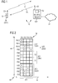
- FIG. 1 shows a mobile network, which can also be referred to as a mobile data transmission network or mobile telecommunications network.
- the mobile network 10 is a UMTS network in the embodiment.
- the mobile network Fig. 10 shows a network of a UMTS successor technology or a 4th generation network.
- the mobile network 10 includes a plurality of base stations, which are also referred to as Node B in the case of UMTS. In the following, however, the base station BS is also used in the case of UMTS.
- the mobile network includes a plurality of mobile terminals, which are referred to as a mobile device M or alternatively UE (User Equipment, user device) or as a mobile phone.
- FIG. 1 shows a base station BS and a mobile radio device M1 or UE1.
- the mobile device M1 contains, for example, an antenna 20, which is used as a transmitting antenna and also as a receiving antenna.
- the mobile device M1 includes a control unit S1, which contains, for example, a microprocessor or only a circuit without a processor.
- the mobile device M1 is particularly suitable for generating or receiving and processing the messages N2 to N10 explained below with reference to FIGS. 3 to 7.
- the base station BS1 contains inter alia an antenna 30 which is used as a transmitting antenna and as a receiving antenna.
- the base station BS1 contains a control unit S2 which contains one or more microprocessors or a circuit arrangement which operates without a program.
- the base station BS1 is in particular capable of receiving and processing or compiling and transmitting the messages N2 to N10 explained below with reference to FIGS. 3 to 7.
- uplink transmission direction UL From the mobile device M1 to the base station BS1 there is a so-called uplink transmission direction UL.
- downlink transmission direction DL which is directed from the base station BS1 to the mobile device M1 or UE1.
- the data transmission capacity on the uplink UL and on the downlink DL may be the same or different from each other, whereby in the downlink direction often a multiple of the data transmission capacity is available than in the uplink direction UL.
- FIG. 1 also shows a connection to a data transmission network 31 to which the base station BS1 is connected.
- the data transmission network 31 is used to forward the subscriber traffic and for administrative and administrative purposes, which are not further elaborated here.
- FIG. 2 shows an allocation scheme 36, which is determined only during network operation, for example, depending on changing transmission conditions or depending on the amount of data to be transmitted between the base station BS1 and the mobile device M1 or in the opposite direction.
- the allocation scheme 36 is shown in a coordinate system 40.
- the coordinate system includes an x-axis 42, on which the time t is shown.
- the time frame is displayed, for example, by synchronization bits of the network elements.
- the time frame ZR1 has a duration of 0.5 milliseconds alternatively of 0.667 milliseconds, so that, for example, fifteen time frames could be arranged in a superordinate time frame of 10 milliseconds.
- a time frame ZR1 may also have a length of 0.2 ms or 2 ms, or a variable or arbitrary length.
- the coordinate system 40 has a ⁇ -axis 44 on which the frequency f is indicated.
- frequency ranges FB1 to FB12 are within a range permitted for mobile transmission, for example in the range greater than 1.5 gigahertz and less than 2.5 gigahertz, or in frequency bands between 3.4 gigahertz to 4.2 gigahertz, 4.5 gigahertz to 4.9 gigahertz, as well as in frequency bands lower than 1.5 gigahertz.
- the frequency ranges FB1 to FB12 are the same size in the embodiment and, for example, each contain only one carrier frequency. In other embodiments, these frequency ranges may be different in magnitude and / or may each include multiple carrier frequencies, for example, 3 to 10 carrier frequencies, preferably, for example, 5 carrier frequencies.
- the base station BS1 assigns the available frequency ranges FB1 to FB12 to users with terminals UE1 to UE4 in the manner explained below.
- four consecutive time slots ZS1 to ZS4 are considered. In other embodiments, however, there are a different number of time slots in a time frame, for example one, three, or six or more than ten time slots. However, the number of time slots per time frame is preferably less than, for example, 50.
- the base station wants to assign the frequency range FB5 to FB8 as a localized data transmission channel DUK1 to the user terminal UE1. Therefore, in the first embodiment, the data transfer channel DUK1 is assigned the highest priority or the highest priority.
- a user terminal UE2 is to be assigned a distributed data transmission channel DUK2. Therefore, the base station BS1 occupies frequency ranges for the data transmission channel DUK2 according to a predetermined calculation scheme, with larger spaces between these frequency ranges, see For example, in the time slot ZS1 frequency range FB4 and frequency range FB12, which are marked by a cross that marks the data transmission channel DUK2.
- the calculation scheme is given, for example, using the modulo function, but the exact assignment function is irrelevant to the present invention.
- the data transmission channel DUK2 lies in the frequency range FB2 and in the frequency range FB10.
- the data transmission channel lies in the frequency range FB3 and in the frequency range FB11.
- the data transmission channel DUK2 lies in the frequency range FB1 and FB9.
- the base station BS1 with a lower priority than the priority of the data transmission channel DUK2 transfers a data transmission channel DUK3 to the terminal UE3.
- the data transmission channel DUK3 is a localized data transmission channel in the frequency range FB1 to FB4, it may be used or "dotted" by distributed data transmission channels, see, for example, the use of the frequency range FB4 for the data transmission channel DUK2 in time slot ZS1.
- the data transmission channel DUK4 lies in the frequency range FB9 to FB12 and is thus also a localized data transmission channel, which, however, can also be "dotted" again by distributed data transmission channels, for example time slot ZS1, frequency range FB12.
- the determination of the allocation scheme 36 by the base station BS1 is signaled in the exemplary embodiment to all mobile devices M1, etc. in the considered cell of the mobile network 10, whereby priorities or priority rules are observed. This shortens the amount of data to be transferred.
- the messages N2 to N10 used for signaling as alternatives are explained in greater detail below with reference to FIGS. 3 to 7.
- Each terminal M1 or UE1 then knows all priorities as well as its own priority and thus can determine whether it must prioritize certain frequency ranges used by other devices or whether it has priority. Thus, collisions can be easily prevented or resolved.
- the distributed data transmission channels are distributed, for example, according to a different scheme, as shown in Figure 2.
- time frames are transmitted, which, for example, have a similar structure to the time frame ZR1, but possibly with different allocation schemes, for the same terminals or also for other terminals.
- the lowest priority user terminals UE1 to UE4 are indicated before higher priority user terminals UE1 to UE4 in the order.
- the order in which the terminal identifier UE1 and the associated frequency range are specified in a data field D2 to D8 can be swapped.
- the order of the data fields D12 to D18 is therefore unrelated to the priority or the priority of certain data transmission channels.
- the order of the terminals in the data fields D12 to D18 is determined by the order in which the terminals UE1 to UE4 have registered with the base station BS1.
- This embodiment has the advantage that the order is not predetermined by the priorities, thus the order can be used to signal other properties or information for the transmissions.
- the order of the data in the respective data fields D12, D14, D16 and D18, respectively is different from the specified order.
- the data fields D12 to D18 may contain further data.
- message N6 contains further data, as shown at arrow 46.
- these may be data fields that contain user terminal allocations that are then assigned to a last lowest priority class. It is therefore not absolutely necessary for the last class to communicate the number of assigned terminals.
- the order of the data fields D32 to D38 for the priority or for the priority is not significant. This is in contrast to, for example, the cases of the message N2, see FIG. 3, or the message N6, see FIG. 5, whereby explicit priority information in particular could also be included in the message N6, for example to further grade the priority within a class. In this exemplary embodiment and correspondingly also in others with explicit priority information, it is also possible to determine how to proceed when a collision of distributed and localized allocations with the same priority occurs in a frequency range. You can specify in advance which allocation has priority in this special case. This priority scheme may continue to depend on the priority, for example, priority L may take precedence over distributed allocation and priority H over localized allocation.
- FIG. 7 shows a message N10.
- the rule is that localized allocations take precedence, whereas otherwise distributed allocations take precedence. It can in this embodiment so happen that in a first frequency range a first user with localized allocation takes precedence over a second user with distributed allocation, whereas in a second frequency range the same first user does not take precedence over this second user. In this respect, this embodiment is more general than the previous ones.
- All messages N2 to N10 may contain additional data fields, eg.
- data required for the further processing of the payload data such as music data, voice data or image data, such as information for coding (eg coding type, coding rate) or modulation method (eg QPSK (Quadrature Phase Shift Keying, n-QAM (Quadrature Amplitude Modulation), where n denotes a natural number greater than 4)
- the information contained in the messages N2 to N10, respectively are transmitted in a plurality of consecutive messages.
- the prioritization can also be expressed by the message in which the allocation is transmitted. For example, all allocations in the first message may receive a higher prioritization than the transmissions in subsequent messages. Within a message, the prioritization can be made as shown in the other embodiments. Similarly, the allocations transferred in a second message may have a higher priority than those in a third message, and so on.
- the order of the messages must not be timed (first and second message can also be transmitted simultaneously) but can be determined by any order method or order criterion, z. For example, on the frequency at which the corresponding message is transmitted - eg messages indicating larger priorities on higher frequencies than messages indicating smaller priorities.
- This method is particularly useful when the individual mobile stations are located at different distances or shading or interference, etc. of the base station. In that case, messages that are also to reach the remote mobile stations have to be sent out with much higher performance, alternatively with better error protection, more robust modulation methods, etc., than messages for mobile stations located nearer.
- the nearby mobile stations can also receive the messages intended for the remote mobile stations, but not vice versa.
- the messages sent with the highest performance should also receive the highest priority for the allocation.
- Messages that are sent with lower performance receive a correspondingly lower priority.
- a mobile station should only be able to receive messages containing its own allocation as well as those containing a higher priority, because only these can punctuate their own allocation.
- messages with lower-priority allocations have no influence and should therefore not be able to be received or received and can therefore be transmitted at lower power.
- such a convention in the allocation of priorities allows a power saving in the resource signaling.
- the messages N2 to N10 can be transmitted, for example, in a control channel, the known bit positions or symbol positions is transmitted or its positions are known or made in a suitable manner the terminals.
- FIG. 8 shows the use of fixed allocation schemas AS1 and optionally AS2.
- the users or more precisely individual terminals or services used by the terminals, are assigned to predetermined data transmission channels.
- the allocation scheme AS1 could correspond to the allocation scheme 36.
- the allocation scheme AS1 is stored in a base station BS2, for example hardwired or in a memory.
- the base station BS2 transmits the Allokationsschema AS1 in a first variant to a mobile device M2, see signaling SI.
- the Allokationsschema AS1 is stored in the mobile device M2 or hardwired, see arrow 52.
- the Allokationsschema AS1, or AS2 before assigning the resources saved to terminals.
- the base station BS2 assigns certain terminals UE1 to UE4 to the data transmission channels DUK1 to DUK4, see FIG. 2, but this may also deviate from the representation shown in FIG. The assignment is signaled to the respective terminal, see signaling SI.
- allocation schemes AS1 and AS2 there are two different allocation schemes AS1 and AS2. Both allocation schemes AS1 and AS2 are stored, for example, only in the base station BS2 in a first variant. In a second variant, the allocation schemes AS1 and AS2 are stored or wired both in the base station BS2 and in the mobile radio M2. In the first variant, the base station BS2 signals the current allocation scheme AS1 or AS2 to the terminals, see signaling SI.
- the base station BS2 signals to at least one terminal M2 which allocation scheme is to be selected, see signaling SI. This can be done, for example, by transmitting the current allocation scheme AS1 or AS2. Alternatively, however, not the allocation scheme but only a selection date is transmitted which identifies one of the allocation schemes. Thereafter, the base station BS2 signals the assignment of terminals to the now again rigidly predetermined data transmission channels DUK1 to DUK4.
- frequency ranges are defined which may not be used by distributed channels.
- these areas are then left out.
- a localized channel can still be assigned to this area and is protected at least in this area against puncturing by a distributed channel.
- a localized channel is protected against puncturing in one subarea and not in another subarea, see dashed circles in FIG. 2, wherein a subarea T1 of the data transfer channel DUK1 is protected by puncturing while the remaining subarea T2 of the data transfer channel DUK1 can certainly be punctured, see circle in time slot ZS1, frequency range FB7.
- puncturing by localized channels with lower priority or with lower priority can also be ruled out in this subarea T2, so that in the exemplary embodiment in the frequency range FB7 and FB8 there are no crosses which represent recesses for the communication channel DUK2.
- subareas T1 are also possible if the schemes are not fixed but dynamic, see scheme 36. In this case, there are then, for example, two data fields which describe the data transfer channel DUK1, the priority being different in both data fields.
Landscapes
- Engineering & Computer Science (AREA)
- Computer Networks & Wireless Communication (AREA)
- Signal Processing (AREA)
- Mobile Radio Communication Systems (AREA)
Priority Applications (2)
| Application Number | Priority Date | Filing Date | Title |
|---|---|---|---|
| EP06016828A EP1887714A1 (fr) | 2006-08-11 | 2006-08-11 | Procédé et appareil d' attribution de ressources conformement avec multiplexage en frequence |
| PCT/EP2007/057855 WO2008017609A1 (fr) | 2006-08-11 | 2007-07-30 | Procédé d'allocation de ressources selon un procédé de multiplexage en fréquence et dispositifs |
Applications Claiming Priority (1)
| Application Number | Priority Date | Filing Date | Title |
|---|---|---|---|
| EP06016828A EP1887714A1 (fr) | 2006-08-11 | 2006-08-11 | Procédé et appareil d' attribution de ressources conformement avec multiplexage en frequence |
Publications (1)
| Publication Number | Publication Date |
|---|---|
| EP1887714A1 true EP1887714A1 (fr) | 2008-02-13 |
Family
ID=37596191
Family Applications (1)
| Application Number | Title | Priority Date | Filing Date |
|---|---|---|---|
| EP06016828A Withdrawn EP1887714A1 (fr) | 2006-08-11 | 2006-08-11 | Procédé et appareil d' attribution de ressources conformement avec multiplexage en frequence |
Country Status (2)
| Country | Link |
|---|---|
| EP (1) | EP1887714A1 (fr) |
| WO (1) | WO2008017609A1 (fr) |
Cited By (1)
| Publication number | Priority date | Publication date | Assignee | Title |
|---|---|---|---|---|
| US9386444B2 (en) | 2007-10-30 | 2016-07-05 | Koninklijke Philips N.V. | Method of signalling information |
Citations (7)
| Publication number | Priority date | Publication date | Assignee | Title |
|---|---|---|---|---|
| US5448750A (en) * | 1992-04-22 | 1995-09-05 | Telefonaktiebolaget Lm Ericsson | Segregation method of dynamic channel allocation in a mobile radio system |
| WO1998059517A1 (fr) * | 1997-06-23 | 1998-12-30 | Telefonaktiebolaget Lm Ericsson | Affectation de canaux pour un melange de services a multi-creneau |
| US5903842A (en) * | 1995-07-14 | 1999-05-11 | Motorola, Inc. | System and method for allocating frequency channels in a two-way messaging network |
| US6064662A (en) * | 1994-04-28 | 2000-05-16 | At&T Corp | System and method for optimizing spectral efficiency using time-frequency-code slicing |
| WO2000074250A2 (fr) * | 1999-05-31 | 2000-12-07 | Siemens Aktiengesellschaft | Procede de transmission d'informations et station radio |
| WO2001093618A1 (fr) * | 2000-05-30 | 2001-12-06 | Siemens Aktiengesellschaft | Procede d'attribution de canal dans un systeme de radiocommunication |
| WO2002049306A2 (fr) * | 2000-12-15 | 2002-06-20 | Broadstorm Telecommunications, Inc. | Communications a ondes porteuses multiples avec attribution d'ondes porteuses basee sur des groupes |
-
2006
- 2006-08-11 EP EP06016828A patent/EP1887714A1/fr not_active Withdrawn
-
2007
- 2007-07-30 WO PCT/EP2007/057855 patent/WO2008017609A1/fr not_active Ceased
Patent Citations (7)
| Publication number | Priority date | Publication date | Assignee | Title |
|---|---|---|---|---|
| US5448750A (en) * | 1992-04-22 | 1995-09-05 | Telefonaktiebolaget Lm Ericsson | Segregation method of dynamic channel allocation in a mobile radio system |
| US6064662A (en) * | 1994-04-28 | 2000-05-16 | At&T Corp | System and method for optimizing spectral efficiency using time-frequency-code slicing |
| US5903842A (en) * | 1995-07-14 | 1999-05-11 | Motorola, Inc. | System and method for allocating frequency channels in a two-way messaging network |
| WO1998059517A1 (fr) * | 1997-06-23 | 1998-12-30 | Telefonaktiebolaget Lm Ericsson | Affectation de canaux pour un melange de services a multi-creneau |
| WO2000074250A2 (fr) * | 1999-05-31 | 2000-12-07 | Siemens Aktiengesellschaft | Procede de transmission d'informations et station radio |
| WO2001093618A1 (fr) * | 2000-05-30 | 2001-12-06 | Siemens Aktiengesellschaft | Procede d'attribution de canal dans un systeme de radiocommunication |
| WO2002049306A2 (fr) * | 2000-12-15 | 2002-06-20 | Broadstorm Telecommunications, Inc. | Communications a ondes porteuses multiples avec attribution d'ondes porteuses basee sur des groupes |
Cited By (1)
| Publication number | Priority date | Publication date | Assignee | Title |
|---|---|---|---|---|
| US9386444B2 (en) | 2007-10-30 | 2016-07-05 | Koninklijke Philips N.V. | Method of signalling information |
Also Published As
| Publication number | Publication date |
|---|---|
| WO2008017609A1 (fr) | 2008-02-14 |
Similar Documents
| Publication | Publication Date | Title |
|---|---|---|
| DE10338053B4 (de) | Verfahren zur Zuweisung von Funkressourcen und Netzeinrichtung in einem Mehrträgerfunkkommunikationssystem | |
| EP1530855B1 (fr) | Procede d'attribution de ressources radio dans un systeme de communication radio auto-organise | |
| EP1502472B1 (fr) | Procede et systeme de radiocommunication destine a la transmission de donnees utiles en tant que service a plusieurs postes de reseau | |
| EP2041938B1 (fr) | Réglage de filtre dépendant de l'occupation de la bande adjacente | |
| DE19882703B4 (de) | Verfahren und Einrichtung in einem Mobiltelekommunikationsnetz | |
| EP1849324B1 (fr) | Affectation dynamique de ressources dans un systeme de communication a porteuses multiples | |
| WO2005043947A1 (fr) | Procede pour faire fonctionner deux systemes de communication radio | |
| EP1586206B1 (fr) | Procede pour synchronisation dans des systemes de radiocommunication | |
| EP1887714A1 (fr) | Procédé et appareil d' attribution de ressources conformement avec multiplexage en frequence | |
| EP1716659B1 (fr) | Procede et dispositif pour l'allocation de sous-bandes d'une bande de frequence | |
| EP1844622B1 (fr) | Procede de groupage et d'affectation de ressources radio dans un systeme a ondes porteuses multiples | |
| WO1999067966A1 (fr) | Procede pour transmettre des informations d'organisation | |
| WO2007128793A2 (fr) | Procédé pour transmettre des données dans un réseau radio, réseau radio et récepteur | |
| DE19912198C1 (de) | Verfahren und Einrichtung zur Übertragung von Informationen über eine Funkschnittstelle | |
| EP1835777B1 (fr) | Allocation de ressources dans un système de radiocommunication multiporteuse | |
| DE102005008053B4 (de) | Kommunikation in einem OFDMA-System mit Aufteilung der Subbänder in Signalisierungs- und Nutzdatensubbänder | |
| DE102024108357A1 (de) | Verfahren zur koordinierten aufwärtskommunikation für nebeneinander existierende luftgestützte und terrestrische benutzer | |
| EP1681801A1 (fr) | Procédé et station de base pour faire fonctionner une système de WIMAX | |
| EP1773084A1 (fr) | Déplacement des resources de radio pour moyenner l'interference inter-cellulaire | |
| DE112021005575T5 (de) | Kommunikationsvorrichung, infrastrukturausrüstung und verfahren | |
| EP1763147A1 (fr) | Séquences de saut pour OFDMA entrelacé et pour IFDMA | |
| DE102006037756A1 (de) | Verfahren zum Übermitteln von Daten, Nachrichtenerzeugungsanordnung, Verfahren zum Empfangen von Daten und Anordnung zum Empfangen von Daten | |
| DE112020004714T5 (de) | Verfahren und kommunikationsvorrichtungen | |
| EP1566909A1 (fr) | Procédé et dispositif pour la communication sans fil en direction descendante en utilisant des codes non-orthogonales | |
| DE102005060020A1 (de) | Sendeleistungsregelung in OFDMA-Systemen |
Legal Events
| Date | Code | Title | Description |
|---|---|---|---|
| PUAI | Public reference made under article 153(3) epc to a published international application that has entered the european phase |
Free format text: ORIGINAL CODE: 0009012 |
|
| AK | Designated contracting states |
Kind code of ref document: A1 Designated state(s): AT BE BG CH CY CZ DE DK EE ES FI FR GB GR HU IE IS IT LI LT LU LV MC NL PL PT RO SE SI SK TR |
|
| AX | Request for extension of the european patent |
Extension state: AL BA HR MK YU |
|
| AKX | Designation fees paid | ||
| STAA | Information on the status of an ep patent application or granted ep patent |
Free format text: STATUS: THE APPLICATION IS DEEMED TO BE WITHDRAWN |
|
| 18D | Application deemed to be withdrawn |
Effective date: 20080814 |
|
| REG | Reference to a national code |
Ref country code: DE Ref legal event code: 8566 |