EP1887779A2 - Système et procédé pour intégrer des marques de sécurité miniatures - Google Patents
Système et procédé pour intégrer des marques de sécurité miniatures Download PDFInfo
- Publication number
- EP1887779A2 EP1887779A2 EP07114155A EP07114155A EP1887779A2 EP 1887779 A2 EP1887779 A2 EP 1887779A2 EP 07114155 A EP07114155 A EP 07114155A EP 07114155 A EP07114155 A EP 07114155A EP 1887779 A2 EP1887779 A2 EP 1887779A2
- Authority
- EP
- European Patent Office
- Prior art keywords
- mark
- host image
- miniature security
- parameters
- detection error
- Prior art date
- Legal status (The legal status is an assumption and is not a legal conclusion. Google has not performed a legal analysis and makes no representation as to the accuracy of the status listed.)
- Withdrawn
Links
- 238000000034 method Methods 0.000 title claims abstract description 56
- 238000001514 detection method Methods 0.000 claims abstract description 66
- 238000004088 simulation Methods 0.000 claims description 7
- 238000001914 filtration Methods 0.000 claims description 2
- 238000002372 labelling Methods 0.000 claims 1
- 238000012552 review Methods 0.000 abstract description 5
- 238000013459 approach Methods 0.000 description 7
- 230000008569 process Effects 0.000 description 6
- 238000007639 printing Methods 0.000 description 5
- 230000002265 prevention Effects 0.000 description 4
- 238000012986 modification Methods 0.000 description 3
- 230000004048 modification Effects 0.000 description 3
- 239000003086 colorant Substances 0.000 description 2
- 238000004891 communication Methods 0.000 description 2
- 230000006835 compression Effects 0.000 description 2
- 238000007906 compression Methods 0.000 description 2
- 238000010586 diagram Methods 0.000 description 2
- 238000005516 engineering process Methods 0.000 description 2
- 238000000605 extraction Methods 0.000 description 2
- 238000012545 processing Methods 0.000 description 2
- 238000012795 verification Methods 0.000 description 2
- QTBSBXVTEAMEQO-UHFFFAOYSA-M Acetate Chemical compound CC([O-])=O QTBSBXVTEAMEQO-UHFFFAOYSA-M 0.000 description 1
- 230000009471 action Effects 0.000 description 1
- 230000008901 benefit Effects 0.000 description 1
- 230000005540 biological transmission Effects 0.000 description 1
- 230000003139 buffering effect Effects 0.000 description 1
- 238000004590 computer program Methods 0.000 description 1
- 230000010339 dilation Effects 0.000 description 1
- 230000003628 erosive effect Effects 0.000 description 1
- 230000006870 function Effects 0.000 description 1
- 238000003384 imaging method Methods 0.000 description 1
- 238000003780 insertion Methods 0.000 description 1
- 230000037431 insertion Effects 0.000 description 1
- 238000010330 laser marking Methods 0.000 description 1
- 238000004519 manufacturing process Methods 0.000 description 1
- 239000003550 marker Substances 0.000 description 1
- 230000005055 memory storage Effects 0.000 description 1
- 230000003287 optical effect Effects 0.000 description 1
- 238000009877 rendering Methods 0.000 description 1
- 238000000926 separation method Methods 0.000 description 1
- 238000013519 translation Methods 0.000 description 1
Images


Classifications
-
- H—ELECTRICITY
- H04—ELECTRIC COMMUNICATION TECHNIQUE
- H04N—PICTORIAL COMMUNICATION, e.g. TELEVISION
- H04N1/00—Scanning, transmission or reproduction of documents or the like, e.g. facsimile transmission; Details thereof
- H04N1/32—Circuits or arrangements for control or supervision between transmitter and receiver or between image input and image output device, e.g. between a still-image camera and its memory or between a still-image camera and a printer device
- H04N1/32101—Display, printing, storage or transmission of additional information, e.g. ID code, date and time or title
- H04N1/32144—Display, printing, storage or transmission of additional information, e.g. ID code, date and time or title embedded in the image data, i.e. enclosed or integrated in the image, e.g. watermark, super-imposed logo or stamp
- H04N1/32149—Methods relating to embedding, encoding, decoding, detection or retrieval operations
- H04N1/32309—Methods relating to embedding, encoding, decoding, detection or retrieval operations in colour image data
-
- H—ELECTRICITY
- H04—ELECTRIC COMMUNICATION TECHNIQUE
- H04N—PICTORIAL COMMUNICATION, e.g. TELEVISION
- H04N1/00—Scanning, transmission or reproduction of documents or the like, e.g. facsimile transmission; Details thereof
- H04N1/32—Circuits or arrangements for control or supervision between transmitter and receiver or between image input and image output device, e.g. between a still-image camera and its memory or between a still-image camera and a printer device
- H04N1/32101—Display, printing, storage or transmission of additional information, e.g. ID code, date and time or title
- H04N1/32144—Display, printing, storage or transmission of additional information, e.g. ID code, date and time or title embedded in the image data, i.e. enclosed or integrated in the image, e.g. watermark, super-imposed logo or stamp
- H04N1/32149—Methods relating to embedding, encoding, decoding, detection or retrieval operations
- H04N1/32203—Spatial or amplitude domain methods
- H04N1/32229—Spatial or amplitude domain methods with selective or adaptive application of the additional information, e.g. in selected regions of the image
Definitions
- This disclosure relates generally to methods and systems for counterfeit prevention, and more particularly to a system and method for automatically embedding miniature security marks in documents or images.
- the simplest method involves flipping the lowest-order bit of chosen pixels in a gray scale or color image. This works well only if the image will not be subject to any human or noisy modification.
- a more robust watermark can be embedded in an image in the same way that a watermark is added to paper. Such techniques may superimpose a watermark symbol over an area of the picture and then add some fixed intensity value for the watermark to the varied pixel values of the image. The resulting watermark may be visible or invisible depending upon the value (large or small, respectively) of the watermark intensity.
- Spatial watermarking can also be applied using color separation.
- the watermark appears in only one of the color bands. This type of watermark is visibly subtle and difficult to detect under normal viewing conditions.
- the colors of the image are separated for printing or xerography, the watermark appears immediately. This renders the document useless to the printer unless the watermark can be removed from the color band.
- This approach is used commercially for journalists to inspect digital pictures from a photo-stockhouse before buying un-watermarked versions.
- MSMs Miniature Security Marks
- the MSMs can be embedded in documents or images to be protected. When the documents or images are scanned, processed, and sent to a printer, the MSM detectors in the imaging system may recognize the embedded MSM marks and defeat the counterfeit attempts.
- the MSM has an advantage over existing technologies, such as watermarking, in that it requires only very simple and inexpensive detectors. Consequently, the MSM may be applied to many devices in a cost-effective manner.
- Embedding MSMs in an image is a complicated process involving determination of the best mark locations and adjusting mark parameters. As usually multiple conflicting requirements such as higher detection rate and lower visibility exist, a try-and-error approach requires skill and experience. Additionally, it is labor intensive and usually does not yield optimal results. In order to remedy this problem as well as other problems, a system and method need to be developed to assist in the MSM embedding process.
- U.S. Patent Application Publication No. 2006/0115110 describes a system for authenticating security documents in which a document includes a first surface having a first and second set of print structures and a second surface.
- the sets of print structures cooperate to obscure the location on the first surface of the second set of print structures.
- the second set of print structures is arranged on the first surface so to provide a reflection pattern, such as a diffraction grating.
- the second set of print structures is preferably provided with metallic ink on the first surface.
- U.S. Patent No. 6,694,042 enables a variety of document management functions by printing documents with machine readable indicia, such as steganographic digital watermarks or barcodes.
- the indicia can be added as part of the printing process (after document data has been output by an originating application program), such as by printer driver software, by a Postscript engine in a printer, etc.
- the indicia can encode data about the document, or can encode an identifier that references a database record containing such data.
- a suitable optical input device such as a webcam
- an electronic version of the document can be recalled for editing, or other responsive action can be taken.
- U.S. Patent No. 7,002,704 teaches a system for rendering an electronic image representation associated with a software application program.
- the system includes a PC-based host processor programmed to execute the software application program, a temporary storage device associated with the host processor, and a printer interfaced to the host processor.
- a printer driver routine is operative on the host processor and determines whether the electronic image representation is of a counterfeit document by examining at least a portion of the electronic image representation when stored in the temporary storage device during the course of printing the electronic image representation at the printer.
- the disclosed embodiments provide examples of improved solutions to the problems noted in the above Background discussion and the art cited therein.
- the method includes predicting detection error rates for each pixel location of a host image, defined as a digital representation of at least one recipient of the miniature security marks.
- the detection error rates for each pixel are displayed with the host image on a graphical user interface and the desired miniature security mark locations are selected.
- At least one set of miniature security mark parameters is identified, with the parameters being mark parameters that enable determination of an optimized balance between detectability and visibility of the miniature security marks.
- the host image with the miniature security mark is displayed on the graphical user interface for review and adjustment by an operator.
- a system for embedding miniature security marks within documents and images utilizing a mark parameters database, graphical user interface, and detection simulator.
- the system includes means for predicting detection error rates for each pixel location of a host image, defined as a digital representation of at least one recipient of the miniature security marks.
- the system provides means for detection of the error rates for each pixel. These are displayed with the host image on a graphical user interface and means are provided for selecting the desired miniature security mark locations.
- the system identifies at least one set of miniature security mark parameters, with the parameters being mark parameters that enable determination of an optimized balance between detectability and visibility of the miniature security marks.
- the host image with the miniature security mark is displayed on the graphical user interface for review and adjustment by an operator.
- said parameters include color, size, or shape.
- means for detecting prediction error rates comprises:
- a computer-readable storage medium having computer readable program code embodied in the medium which, when the program code is executed by a computer, causes the computer to perform method steps for embedding miniature security marks within documents and images, utilizing a mark parameters database, graphical user interface, and detection simulator.
- the method includes predicting detection error rates for each pixel location of a host image, defined as a digital representation of at least one recipient of the miniature security marks.
- the detection error rates for each pixel are displayed with the host image on a graphical user interface and the desired miniature security mark locations are selected.
- At least one set of miniature security mark parameters is identified, with the parameters being mark parameters that enable determination of an optimized balance between detectability and visibility of the miniature security marks.
- the host image with the miniature security mark is displayed on the graphical user interface for review and adjustment by an operator.
- FIG. 1 is a functional block diagram of one exemplary embodiment of a system for embedding MSMs in documents and/or images;
- FIG. 2 is a flowchart outlining one exemplary embodiment of the method for embedding MSMs in documents and/or images
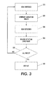
- FIG. 3 is a flow chart outlining one exemplary embodiment of prediction of detection error rates
- FIG. 4 is a flow chart outlining one exemplary embodiment of parameter determination within the method for embedding MSMs in documents and/or images.
- FIG. 5 is a flow chart outlining another exemplary embodiment of parameter determination within the method for embedding MSMs in documents and/or images illustrates.
- the semi-automated MSM embedding system and method improve upon the existing methods for embedding MSMs in documents or images.
- image refers to a graphic or plurality of graphics, compilation of text, a contone or haftone pictorial image, or any combination or subcombination thereof, that is capable of being output on a display device, a marker and the like, including a digital representation of such image.
- an image may be a combination of graphics, text and pictures that is represented by a series of pixel values denoting the color, intensity, etc., of the particular pixels that make up the image.
- the system includes a user interface, a detection simulator, and a database that stores mark parameters.
- the embedding method includes prediction of the detection error rates for each image location through simulation and displays the result on the user interface. Using the prediction information, an operator selects the desired mark locations. The system then automatically selects a set of parameters that maximizes the balance between detectability of the marks and visibility of them according to operator-determined metrics. These parameters may be adjusted by the operator and the results placed in the database.
- Various computing environments may incorporate capabilities for supporting a network on which the system and method for embedding MSMs may reside.
- the following discussion is intended to provide a brief, general description of suitable computing environments in which the method and system may be implemented.
- program modules include routines, programs, objects, components, data structures, etc., that perform particular tasks or implement particular abstract data types.
- program modules include routines, programs, objects, components, data structures, etc., that perform particular tasks or implement particular abstract data types.
- the method and system may be practiced with other computer system configurations, including hand-held devices, multi-processor systems, microprocessor-based or programmable consumer electronics, networked PCs, minicomputers, mainframe computers, and the like.
- the method and system may also be practiced in distributed computing environments where tasks are performed by remote processing devices that are linked through a communication network.
- program modules may be located in both local and remote memory storage devices.
- a security mark as used herein can be any mark (e.g., depression, impression, raised, overlay, etc.) that is applied to a recipient such as an image, a graphic, a picture, a document, a body of text, etc.
- the security mark can contain information that can be detected, extracted and/or interpreted. Such information can be employed to prevent counterfeiting by verifying that the information contained within the security mark is accurate, thereby verifying the authenticity of the recipient upon which the security mark is applied.
- the system includes data reception source 110, MSM embedding module 120, memory 160, and application module 170. These devices are coupled together via data communication links which may be any type of link that permits the transmission of data, such as direct serial connections, a local area network (LAN), wide area network (WAN), an intranet, the Internet, circuit wirings, and the like.
- the data reception source 110 receives information from one or more sources (not shown). Such sources can be one or more databases, processing components, etc. that contain information related to one or more products (e.g., currency, passports, visas, banking documents, identification documents, etc.). In some cases, verification of authenticity of the one or more products is of interest to a user. In order to provide a means to verify authenticity, one or more security marks can be placed on the product. Such security marks can be detected and extracted at a later time for verification purposes.
- Data can be representative of substantially any desired quantity such as origin of manufacture, date, time, serial number or simply an arbitrary alphanumeric string.
- the data is proprietary such that only a limited number of users can interpret the data.
- the MSM embedding module 120 can convert received data into one or more MSM(s), which is placed in a particular configuration. MSMs are small in size (e.g., a size between about 1 micrometer and several hundred micrometers) such that they are virtually invisible to the naked eye. Information from the data reception component 110 can be employed to generate one or more MSMs.
- the marks that comprise a MSM configuration can be composed via one or more algorithms that convert the received data to a configuration of marks that are representative of the received data.
- the algorithm can utilize one or more equations, methodologies, work flows, etc. to determine the locations, sizes and/or shapes of the one or more marks. Such a determination can be made based at least in part upon one or more aspects of one or more disparate marks.
- MSM embedding module 120 includes user interface 130, detection simulator 140 and mark parameters database 150.
- Detection simulator 140 predicts the detection error rates for each pixel location in the recipient host image and the results are displayed on the user interface 130 with the host image. The results may be displayed as separate images on the screen or overlapped. Overlapping may be accomplished, for example, through use of a luminance channel to present the host image and use of chrominance channels to present the detection error rates, or by any other means known in the art.
- Mark parameters database 150 selects a set of mark parameters that provides the optimum compromise between the detectability and the visibility of the MSMs. Mark parameters may include, for example, color, size, and shape.
- the metrics applied to optimize the combination of detectability and visibility may be selected by the operator and include ensuring acceptable detectability and minimizing visibility, or ensuring acceptable visibility and maximizing detectability.
- the host image containing the embedded marks with the selected parameters is displayed on the user interface 130 for review by the operator. Operation of detection simulator 140 and mark parameters database 150 are discussed more fully herein with reference to Figures 2-4.
- Algorithms can employ substantially any method to determine the location, size, shape, etc. of the data marks and/or anchor marks within a MSM configuration. For example, key dependency, mathematical morphology, etc. can be employed. Algorithms utilizing mathematical morphology can process an image utilizing a structuring element, erosion and/or dilation, for example. Informed embedding can be employed utilizing blind extraction. In one example, various techniques are employed to create compact non-authentic regions and to remove noise due to high quality compression from a false detection map. Utilizing mathematical morphology, the tampered regions can be located and noise (e.g., from lossy compression, etc.) is reduced. In another example, an algorithm that creates a geometrically invariant feature based security mark is created. Such a mark remains constant under rotation, scale, translation, etc.
- the memory 160 can contain one or more algorithms, look up tables, etc. in order to provide a method of generating a particular MSM configuration. New algorithms employed by the MSM embedding module 120 can be transmitted to the memory 160. In this manner, algorithms can be stored, viewed, edited, organized and retrieved for subsequent use. Selection of an algorithm can be based on a plurality of factors such as data source, user preference, time constraints, footprint constraints, data constraints, surface type, etc.
- the application component 170 can apply one or more security marks received from the MSM embedding module 120 to one or more recipients.
- the application component 170 is a printing platform that can place an MSM configuration on a recipient (e.g., paper, velum, acetate, etc.) based at least in part upon commands received from the MSM embedding module 120. In this manner, a print head, an applicator or the like can move to one or more locations relative to the recipient and distribute ink in specified locations to create a particular MSM configuration.
- the application component is a laser marking system that removes and/or discolors a surface of the recipient in order to create a particular MSM configuration. It is to be appreciated that the application component 16 can be substantially any device that can create one or more marks on a recipient.
- the particular methods performed for embedding MSMs comprise steps which are described below with reference to a series of flow charts.
- the flow charts illustrate an embodiment in which the methods constitute computer programs made up of computer-executable instructions. Describing the methods by reference to a flowchart enables one skilled in the art to develop software programs including such instructions to carry out the methods on computing systems.
- the language used to write such programs can be procedural, such as Fortran, or object based, such as C++.
- One skilled in the art will realize that variations or combinations of these steps can be made without departing from the scope of the disclosure herein.
- FIG. 2 a flowchart illustrates an example embodiment of the method for embedding MSMs in documents and/or images.
- detection error rates are predicted for each pixel location of the host image, which is the digital representation of the recipient.
- the results are displayed to the operator with the host image.
- the results and the host image may be displayed separately on a single screen, for example side-by-side, or the images may be overlapped.
- Various known methods such as using a luminance channel to show the host image and using chrominance channels to show the detection error rates may be utilized to overlap the images.
- the operator may then select the desired mark locations at 220. While locations having lower detection errors are generally preferred, other factors, such as balance in location (to avoid concentrations of marks in a single region), may need to be considered.
- a set of mark parameters are selected at 230 by the system.
- the mark parameters provide an optimized balance between the detectability and visibility of the MSMs. While for the purposes of discussion, color is utilized as an example parameter, alternate parameters such as mark size and shape may be used.
- the system identifies the background color, which is the host image color around the mark location. It then searches the database to locate the mark color that will ensure a lower bound for detectability while minimizing visibility. Alternatively, a metric may be applied to impose a limit for visibility while maximizing the detection. It is noted that other metrics that optimize a combination of both detectability and visibility may also be applied, all of which are contemplated by the scope of the discussion and claims herein.
- the user interface presents various metrics to the operator for selection.
- the host image containing the embedded marks with the selected parameters is displayed on the user interface at 240.
- the operator may modify the mark parameters through the user interface if the selection is not satisfactory. Otherwise, the operator may save the file to memory and complete the embedding process through application of the MSMs by the system application module.
- an MSM is embedded at a first pixel location of the host image. If it is not possible to embed an MSM at a particular location, for example at the border of the host image, the error rate for the location is labeled as 100% and a next pixel location is identified. The system then selects the parameters for the MSM such that it ensures a sufficient signal to noise ratio for the detection.
- a set of simulation images is generated at 320 by performing various operations on the embedded host image created at 310. The operations may include but are not limited to rotation, shifting, scaling, and filtering. MSM detection on the simulation images is performed at 330 and the detection rate is recorded at 340.
- the results are displayed on the user interface with the host image at 360.
- the images may be shown as independent or superimposed images.
- Various approaches may be utilized to superimpose the images, with one example being use of a luminance channel to show the host image and use of chrominance channels to show the detection error rates.
- the flow chart illustrates an example embodiment of a method for parameter determination within the method for embedding MSMs in documents and/or images.
- the system automatically selects a set of mark parameters that provides an optimized balance between detectability and visibility of the MSMs.
- Various parameters such as mark color (described below with reference to Figure 5), mark size, mark shape, or any other parameters known in the art may be utilized.
- the system is initialized with the current specified visibility, V sel , initially set at infinity.
- V sel the current specified visibility
- the system identifies the host background information for the parameter selected at 420.
- the system searches the database to identify the best parameter set that minimizes the mark visibility while its detectability exceeds a pre-determined threshold.
- a determination is made at 430 as to whether the identified mark parameter set is the last of the parameter set to be checked in the database. If it is the last parameter set to be checked in the database, it is determined whether the visibility equals infinity at 440. If the visibility equals infinity, no parameter is selected at 450 and the system returns a message at 455 that a parameter set satisfying the detection and visibility requirements was not identified. If the visibility does not equal infinity, the selected parameter, P sel is identified at 445 and provided to the operator at 455.
- the next candidate mark parameter in the set, P i is identified at 460.
- the system determines whether the candidate parameter satisfies a predetermined threshold for detectability at 470.
- the threshold is set by the system and can be modified by the operator. If the detectability threshold is satisfied, the system calculates the resulting visibility for the candidate mark parameter set at 475. If the detectability threshold is not satisfied, the system returns to 430 and selects a new candidate parameter set from the database.
- Various metrics may be applied to optimize the balance between detectability and visibility, for example minimizing visibility while providing a lower bound for detection as illustrated. Alternatively a metric may be applied to impose a limit for visibility while maximizing detection. Other metrics that optimize a combination of both detectability and visibility may also be used. These options are presented on the system user interface for selection by the operator.
- the system automatically selects a set of mark parameters that provides an optimized balance between detectability and visibility of the MSMs.
- color is used as an example parameter, but other parameters, such as mark size, and mark shape may be used.
- V sel the current specified visibility
- the system identifies the background color, B, which is the host image color around the mark location, at 520. The system then searches the database to identify the best mark color that minimizes the difference between the mark color and the background color under the constraint that the mark detectability is greater than a predetermined threshold.
- the next candidate mark color, M i is identified at 560.
- the system determines whether the difference between the candidate mark color and the background color in the color channel that detection is performed is greater than a predetermined threshold for detectability at 570.
- the threshold is set by the system and may be modified by the operator. If the detectability threshold is exceeded the system calculates the resulting visibility for the difference between the selected color and the background color at 575. If the detectability threshold is not exceeded, the system returns to 530 and selects a new candidate mark color from the database.
- code as used herein, or “program” as used herein, is any plurality of binary values or any executable, interpreted or compiled code which can be used by a computer or execution device to perform a task. This code or program can be written in any one of several known computer languages.
- a "computer”, as used herein, can mean any device which stores, processes, routes, manipulates, or performs like operation on data. It is to be understood, therefore, that this disclosure is not limited to the particular forms illustrated and that it is intended in the appended claims to embrace all alternatives, modifications, and variations which do not depart from the spirit and scope of the embodiments described herein.
Landscapes
- Engineering & Computer Science (AREA)
- Multimedia (AREA)
- Signal Processing (AREA)
- Editing Of Facsimile Originals (AREA)
- Image Processing (AREA)
- Facsimile Image Signal Circuits (AREA)
Applications Claiming Priority (1)
| Application Number | Priority Date | Filing Date | Title |
|---|---|---|---|
| US11/502,987 US7792324B2 (en) | 2006-08-11 | 2006-08-11 | System and method for embedding miniature security marks |
Publications (2)
| Publication Number | Publication Date |
|---|---|
| EP1887779A2 true EP1887779A2 (fr) | 2008-02-13 |
| EP1887779A3 EP1887779A3 (fr) | 2008-07-16 |
Family
ID=38792240
Family Applications (1)
| Application Number | Title | Priority Date | Filing Date |
|---|---|---|---|
| EP07114155A Withdrawn EP1887779A3 (fr) | 2006-08-11 | 2007-08-10 | Système et procédé pour intégrer des marques de sécurité miniatures |
Country Status (3)
| Country | Link |
|---|---|
| US (1) | US7792324B2 (fr) |
| EP (1) | EP1887779A3 (fr) |
| JP (1) | JP4709190B2 (fr) |
Families Citing this family (2)
| Publication number | Priority date | Publication date | Assignee | Title |
|---|---|---|---|---|
| US9277091B2 (en) | 2007-05-22 | 2016-03-01 | Xerox Corporation | Embedding information in paper forms |
| CN111143961B (zh) * | 2018-11-02 | 2024-10-18 | 阿波罗智能技术(北京)有限公司 | 无人车仿真监控定位方法、装置及存储介质 |
Citations (2)
| Publication number | Priority date | Publication date | Assignee | Title |
|---|---|---|---|---|
| US6694042B2 (en) | 1999-06-29 | 2004-02-17 | Digimarc Corporation | Methods for determining contents of media |
| US7002704B1 (en) | 2000-11-06 | 2006-02-21 | Xerox Corporation | Method and apparatus for implementing anti-counterfeiting measures in personal computer-based digital color printers |
Family Cites Families (7)
| Publication number | Priority date | Publication date | Assignee | Title |
|---|---|---|---|---|
| US6067374A (en) | 1997-11-13 | 2000-05-23 | Xerox Corporation | Seal detection system and method |
| JP3156667B2 (ja) * | 1998-06-01 | 2001-04-16 | 日本電気株式会社 | 電子透かし挿入システム、電子透かし特性表作成装置 |
| US6580820B1 (en) | 1999-06-09 | 2003-06-17 | Xerox Corporation | Digital imaging method and apparatus for detection of document security marks |
| JP2002077589A (ja) * | 2000-09-04 | 2002-03-15 | Nippon Telegr & Teleph Corp <Ntt> | 電子透かし埋め込み装置、方法およびプログラム記録媒体 |
| JP2004282356A (ja) * | 2003-03-14 | 2004-10-07 | Ricoh Co Ltd | 画像処理装置、方法および記録媒体 |
| JP4285300B2 (ja) * | 2004-03-31 | 2009-06-24 | 株式会社日立製作所 | 情報埋め込み装置を実現するプログラム,および,情報読み取り装置を実現するプログラム |
| WO2006053023A2 (fr) | 2004-11-09 | 2006-05-18 | Digimarc Corporation | Authentification de documents d'identification et de securite |
-
2006
- 2006-08-11 US US11/502,987 patent/US7792324B2/en not_active Expired - Fee Related
-
2007
- 2007-08-06 JP JP2007204547A patent/JP4709190B2/ja not_active Expired - Fee Related
- 2007-08-10 EP EP07114155A patent/EP1887779A3/fr not_active Withdrawn
Patent Citations (2)
| Publication number | Priority date | Publication date | Assignee | Title |
|---|---|---|---|---|
| US6694042B2 (en) | 1999-06-29 | 2004-02-17 | Digimarc Corporation | Methods for determining contents of media |
| US7002704B1 (en) | 2000-11-06 | 2006-02-21 | Xerox Corporation | Method and apparatus for implementing anti-counterfeiting measures in personal computer-based digital color printers |
Also Published As
| Publication number | Publication date |
|---|---|
| JP4709190B2 (ja) | 2011-06-22 |
| US7792324B2 (en) | 2010-09-07 |
| EP1887779A3 (fr) | 2008-07-16 |
| US20080037822A1 (en) | 2008-02-14 |
| JP2008048401A (ja) | 2008-02-28 |
Similar Documents
| Publication | Publication Date | Title |
|---|---|---|
| CA2618738C (fr) | Systeme et procede pour l'inclusion de marques de securite miniatures dispersees | |
| US7949175B2 (en) | Counterfeit deterrence using dispersed miniature security marks | |
| CN101155239B (zh) | 电子水印嵌入装置及检测装置 | |
| US20040001606A1 (en) | Watermark fonts | |
| EP1667422A1 (fr) | Systeme de traitement d'imprimes, dispositif d'impression de documents contenant des filigranes, dispositif de lecture de documents contenant des filigranes, procede de traitement d'imprimes, dispositif de lecture d'informations et procede de lecture d'informations | |
| EP3050289B1 (fr) | Filigranes numériques | |
| JP2009111980A (ja) | 閉ループ処理における文書の真偽判定 | |
| WO2009142640A1 (fr) | Système d'analyse d'impression de sécurité et procédé d'amélioration d'impression de sécurité | |
| US20080056529A1 (en) | Systems and Methods for Image Watermarking | |
| JP4783003B2 (ja) | 個人認証媒体発行装置および個人認証媒体発行方法 | |
| EP1887779A2 (fr) | Système et procédé pour intégrer des marques de sécurité miniatures | |
| EP1887532B1 (fr) | Système et procédé pour la détection de marques de sécurité miniatures | |
| JP4298588B2 (ja) | 情報検出装置および情報検出方法 | |
| EP1901226A2 (fr) | Marques de sécurité miniatures hiérarchiques | |
| JP2009200794A (ja) | 文書の改竄検出プログラム及び改竄検出装置 | |
| RU2431192C1 (ru) | Способ внедрения скрытого цифрового сообщения в печатаемые документы и извлечения сообщения | |
| JP2005252382A (ja) | 改ざん検証データ入り文書およびその画像、文書出力装置およびその方法、ならびに文書入力装置およびその方法 | |
| TW200406717A (en) | Watermarking | |
| JP2009260886A (ja) | 文書作成支援システム及び文書検証システム | |
| US20080259403A1 (en) | Image processing apparatus, viewer, image processing program and image processing system | |
| EA044006B1 (ru) | Способ внесения цифровых меток в цифровое изображение и устройство для осуществления способа | |
| JP2007306229A (ja) | 画像処理装置、画像形成装置およびプログラム | |
| JP2005311941A (ja) | 画像処理装置、画像処理方法および画像処理プログラム |
Legal Events
| Date | Code | Title | Description |
|---|---|---|---|
| PUAI | Public reference made under article 153(3) epc to a published international application that has entered the european phase |
Free format text: ORIGINAL CODE: 0009012 |
|
| AK | Designated contracting states |
Kind code of ref document: A2 Designated state(s): AT BE BG CH CY CZ DE DK EE ES FI FR GB GR HU IE IS IT LI LT LU LV MC MT NL PL PT RO SE SI SK TR |
|
| AX | Request for extension of the european patent |
Extension state: AL BA HR MK YU |
|
| PUAL | Search report despatched |
Free format text: ORIGINAL CODE: 0009013 |
|
| AK | Designated contracting states |
Kind code of ref document: A3 Designated state(s): AT BE BG CH CY CZ DE DK EE ES FI FR GB GR HU IE IS IT LI LT LU LV MC MT NL PL PT RO SE SI SK TR |
|
| AX | Request for extension of the european patent |
Extension state: AL BA HR MK RS |
|
| 17P | Request for examination filed |
Effective date: 20090116 |
|
| AKX | Designation fees paid |
Designated state(s): DE FR GB |
|
| 17Q | First examination report despatched |
Effective date: 20090312 |
|
| GRAP | Despatch of communication of intention to grant a patent |
Free format text: ORIGINAL CODE: EPIDOSNIGR1 |
|
| INTG | Intention to grant announced |
Effective date: 20171018 |
|
| STAA | Information on the status of an ep patent application or granted ep patent |
Free format text: STATUS: THE APPLICATION IS DEEMED TO BE WITHDRAWN |
|
| 18D | Application deemed to be withdrawn |
Effective date: 20180301 |