EP1888151B1 - Dispositif de protection pour proteger une aiguille de seringue - Google Patents
Dispositif de protection pour proteger une aiguille de seringue Download PDFInfo
- Publication number
- EP1888151B1 EP1888151B1 EP06779771.2A EP06779771A EP1888151B1 EP 1888151 B1 EP1888151 B1 EP 1888151B1 EP 06779771 A EP06779771 A EP 06779771A EP 1888151 B1 EP1888151 B1 EP 1888151B1
- Authority
- EP
- European Patent Office
- Prior art keywords
- sleeve
- protection device
- peg
- injection
- support
- Prior art date
- Legal status (The legal status is an assumption and is not a legal conclusion. Google has not performed a legal analysis and makes no representation as to the accuracy of the status listed.)
- Expired - Lifetime
Links
Images


Classifications
-
- A—HUMAN NECESSITIES
- A61—MEDICAL OR VETERINARY SCIENCE; HYGIENE
- A61M—DEVICES FOR INTRODUCING MEDIA INTO, OR ONTO, THE BODY; DEVICES FOR TRANSDUCING BODY MEDIA OR FOR TAKING MEDIA FROM THE BODY; DEVICES FOR PRODUCING OR ENDING SLEEP OR STUPOR
- A61M5/00—Devices for bringing media into the body in a subcutaneous, intra-vascular or intramuscular way; Accessories therefor, e.g. filling or cleaning devices, arm-rests
- A61M5/178—Syringes
- A61M5/31—Details
- A61M5/32—Needles; Details of needles pertaining to their connection with syringe or hub; Accessories for bringing the needle into, or holding the needle on, the body; Devices for protection of needles
- A61M5/3205—Apparatus for removing or disposing of used needles or syringes, e.g. containers; Means for protection against accidental injuries from used needles
- A61M5/321—Means for protection against accidental injuries by used needles
- A61M5/3243—Means for protection against accidental injuries by used needles being axially-extensible, e.g. protective sleeves coaxially slidable on the syringe barrel
- A61M5/3271—Means for protection against accidental injuries by used needles being axially-extensible, e.g. protective sleeves coaxially slidable on the syringe barrel with guiding tracks for controlled sliding of needle protective sleeve from needle exposing to needle covering position
- A61M5/3272—Means for protection against accidental injuries by used needles being axially-extensible, e.g. protective sleeves coaxially slidable on the syringe barrel with guiding tracks for controlled sliding of needle protective sleeve from needle exposing to needle covering position having projections following labyrinth paths
-
- A—HUMAN NECESSITIES
- A61—MEDICAL OR VETERINARY SCIENCE; HYGIENE
- A61M—DEVICES FOR INTRODUCING MEDIA INTO, OR ONTO, THE BODY; DEVICES FOR TRANSDUCING BODY MEDIA OR FOR TAKING MEDIA FROM THE BODY; DEVICES FOR PRODUCING OR ENDING SLEEP OR STUPOR
- A61M5/00—Devices for bringing media into the body in a subcutaneous, intra-vascular or intramuscular way; Accessories therefor, e.g. filling or cleaning devices, arm-rests
- A61M5/178—Syringes
- A61M5/31—Details
- A61M5/32—Needles; Details of needles pertaining to their connection with syringe or hub; Accessories for bringing the needle into, or holding the needle on, the body; Devices for protection of needles
- A61M5/3205—Apparatus for removing or disposing of used needles or syringes, e.g. containers; Means for protection against accidental injuries from used needles
- A61M5/321—Means for protection against accidental injuries by used needles
- A61M5/3243—Means for protection against accidental injuries by used needles being axially-extensible, e.g. protective sleeves coaxially slidable on the syringe barrel
- A61M5/326—Fully automatic sleeve extension, i.e. in which triggering of the sleeve does not require a deliberate action by the user
-
- A—HUMAN NECESSITIES
- A61—MEDICAL OR VETERINARY SCIENCE; HYGIENE
- A61M—DEVICES FOR INTRODUCING MEDIA INTO, OR ONTO, THE BODY; DEVICES FOR TRANSDUCING BODY MEDIA OR FOR TAKING MEDIA FROM THE BODY; DEVICES FOR PRODUCING OR ENDING SLEEP OR STUPOR
- A61M5/00—Devices for bringing media into the body in a subcutaneous, intra-vascular or intramuscular way; Accessories therefor, e.g. filling or cleaning devices, arm-rests
- A61M5/36—Devices for bringing media into the body in a subcutaneous, intra-vascular or intramuscular way; Accessories therefor, e.g. filling or cleaning devices, arm-rests with means for eliminating or preventing injection or infusion of air into body
-
- A—HUMAN NECESSITIES
- A61—MEDICAL OR VETERINARY SCIENCE; HYGIENE
- A61M—DEVICES FOR INTRODUCING MEDIA INTO, OR ONTO, THE BODY; DEVICES FOR TRANSDUCING BODY MEDIA OR FOR TAKING MEDIA FROM THE BODY; DEVICES FOR PRODUCING OR ENDING SLEEP OR STUPOR
- A61M5/00—Devices for bringing media into the body in a subcutaneous, intra-vascular or intramuscular way; Accessories therefor, e.g. filling or cleaning devices, arm-rests
- A61M5/178—Syringes
- A61M5/31—Details
- A61M5/32—Needles; Details of needles pertaining to their connection with syringe or hub; Accessories for bringing the needle into, or holding the needle on, the body; Devices for protection of needles
- A61M5/3205—Apparatus for removing or disposing of used needles or syringes, e.g. containers; Means for protection against accidental injuries from used needles
- A61M5/321—Means for protection against accidental injuries by used needles
- A61M5/3243—Means for protection against accidental injuries by used needles being axially-extensible, e.g. protective sleeves coaxially slidable on the syringe barrel
- A61M5/326—Fully automatic sleeve extension, i.e. in which triggering of the sleeve does not require a deliberate action by the user
- A61M2005/3267—Biased sleeves where the needle is uncovered by insertion of the needle into a patient's body
Definitions
- the present invention relates to a protection device for protecting a needle so as to protect the patient and/or the user from the risk of needlestick injury, particularly after the said needle has been used.
- syringes may be supplied ready for use or in the form of kits to be assembled, which may or may not be pre-filled with the liquid that is to be injected.
- the liquid that is to be injected is often supplied within a syringe body containing the dose that is to be injected.
- the end of the syringe body may be provided directly with a needle or may be provided with a syringe tip to which a needle support bearing the needle can be fixed.
- This syringe tip is, for example, of the "luer” or "luer lock” type.
- Document EP 409 180 describes a device for protecting a needle comprising a moving sleeve intended to cover the needle after injection.
- this protection device entails the sleeve rotating on itself by a certain amount in order to trigger its deployment, this rotation being performed while the distal end of the sleeve is in contact with the patient's skin, and while the medicinal product is being injected.
- the present invention aims to satisfy this need by proposing a device for protecting a needle that is effective, reliable whith safety operation not directly linked to friction specificities, easy to manufacture and to use, comprises a limited number of parts, can be activated after injection without additional manual intervention on the part of the user so as to cover the needle, the said needle protection device not giving rise to any effect of friction against the patient's skin and limiting the risks of needlestick injury.
- the present invention is also aimed at proposing such a needle protection device that is irreversible, preventing access to the needle once it has been activated.
- the present invention is also aimed at proposing a needle protection device that can be used in any field of medicine, veterinary science and with any injection device such as, for example, syringes, catheters and any other equivalent device.
- the present invention relates to a protection device intended to at least partially cover the needle of an injection device, the said protection device comprising at least:
- the protection device according to the invention is able to protect efficiently the needle of an injection device, at least after injection., Particularly by virtue of the presence of a peg that can move laterally and which is longitudinally linked to the support, the impact of friction problem due to moving parts and that is encountered in other prior art protection devices, is avoided. Therefore, the protection device according to the invention is a more reliable protection device.
- the sleeve of the device according to the invention does not rotate on itself during the entire operation of administering the medicinal product, the injection is at no time disrupted by the effect of friction against the patient's skin, it is therefore easier and safer and can be administered without inconveniencing either of the patient or the user.
- the protection device according to the invention makes it possible to avoid the risks of needlestick injury after injection as the needle is withdrawn from the injection site. What happens, after injection, as the injection device is withdrawn, is that the return means allow deployment of the sleeve without the user having to perform any additional manual operation. The operation of triggering the placement of the sleeve is therefore also safe.
- the present invention also relates to an injection device comprising a needle protection device described hereinabove.
- an injection device ready for use and provided with the said protection device, it being possible for the end of the needle of the injection device to be visible, but nonetheless safe. Indeed, it may be important to nurses to have an injection device in which the end of the needle is visible: that allows them to expel air prior to most injections, with the best possible view of what they are doing. That also allows them better control over the first phase of the operation of injecting the medicinal product, namely the phase of positioning the needle on the injection site and orientating the tip of the needle with a view to inserting it and injecting the medicinal product.
- distal end of a component or a device is to be understood as meaning the end furthest from the user's hand and the proximal end is to be understood as meaning the end closest to the user's hand.
- distal direction is to be understood as meaning the direction of injection
- proximal direction is to be understood as meaning the opposite direction to the direction of injection.
- the "injection surface" may be the patient's skin in the case of an injection, the membrane of a bottle from which the product is taken or in which it is mixed, the end of a tube, of a pipe, the wall of a flexible bag, or of any connecting means.
- the said axial-guidance means are arranged in such a way as also to prevent the said sleeve from pivoting axially as it moves axially with respect to the said support from its storage position to its injection position.
- the said axial-guidance means comprise more or less complementary longitudinal geometric shapes provided respectively on the said sleeve and on the said support and arranged facing one another in order to collaborate.
- These geometric shapes may be grooves, ribs, bulges or alternatively slideways.
- the said first and second sections of the said running passageway are joined together by a first narrowed region defined by a flexible tongue at least partially defining the said first safety means.
- the peg may be solid and made of a deformable material; it may be hollow, its walls deforming inwards, or may be formed of flexible tabs.
- the said peg is urged laterally from the said first section towards the said second section by second return means at least partially defining the said first safety means.
- the said support or, respectively, the said sleeve comprises at least one tab able to deflect tangentially and bearing the said peg.
- the said tab is arranged in such a way as to deflect tangentially in an elastically deformable manner between a normal position and at least one stressed deflected position, said tab at least partially defining the said first safety means.
- the said tab is in a normal position or, respectively, in a stressed deflected position when the said peg is in the said first section, and the said tab is in the stressed deflected position or, respectively, in the normal position when the said peg is in the said second section.
- the said tab may be made of an elastically deformable material.
- the said tab may also comprise a pivot connection or a ball joint, which is elastically deformable, it being possible for this connection to be coupled to these return means.
- the said first and second sections have different lengths arranged in such a way as to delimit the said storage and protection positions such that the said distance 13 is greater than the said distance 11.
- the said sleeve facing the said running passageway provided on the said sleeve or, respectively, on the said support, the said support or, respectively, the said sleeve comprises a deflection passage arranged in such a way as to guide the said peg laterally.
- the said protection device comprises second safety means arranged in such a way as to block the said peg when the said sleeve is in the said protection position.
- the said second section of the said running passageway comprises a second narrowed region at least partially defining the said second safety means.
- the said second section of the said running passageway comprises at least one step forming a stop catch for the said peg when the said sleeve is in the said protection position and at least partially defining the said second safety means.
- the said running passageway and/or the said deflection passage is formed of at least one element chosen from the group comprising a groove, a slot, a rib or a combination of these elements.
- the said first and/or second return means are elastically deformable and chosen from the group comprising a helical spring, an elastic leaf, an elastically deformable element.
- the said first return means are arranged between the proximal end of the said support and the distal end of the said sleeve.
- the said sleeve or, respectively, the said support comprises at least one stop wall situated facing the said tab when the device is in the protection position, the said stop wall being arranged in such a way as to prevent the radial deflection of the said tab towards the axis of the said protection device in this protection position.
- the said support is provided with an injection needle.
- the present invention also relates to an injection device comprising at least one injection needle and a reservoir of product that is to be injected, characterized in that it comprises at least one protection device as described hereinabove.
- the present invention also relates to a set comprising a device as described hereinabove and packaging for this device, the said packaging comprising a cylindrical body and a cap, the said cylindrical body being equipped on its internal wall with means for blocking the rotation and translation of the said device within the said packaging.
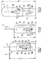
- Figure 1 depicts a protection device 1 for protecting an injection needle 2 according to the invention.
- This protection device 1 comprises a support 3 for a needle 2 and a sleeve 4 arranged in such a way as to accept the support 3.
- This sleeve 4 can be moved in translation with respect to the support 3, from a storage position depicted in Figure 2 towards a second position, the injection position, depicted in Figure 3 and towards a third position, the protection position, depicted in Figure 4 .
- the support 3 and the sleeve 4 each comprise means for the guidance and axial translation of the support 3 with respect to the sleeve 4: in Figure 1 , these guide means are in the form of diametrically opposed longitudinal bulges 29 situated on the external wall of the support 3, these longitudinal bulges 29 collaborating with diametrically opposed slideways 30 situated on the internal wall of the sleeve 4, facing the said bulges 29.
- the support 3 comprises a flexible tab 5 which runs longitudinally from the proximal part of the support 3 in the distal direction.
- This flexible tab 5 at its distal end comprises a peg 6.
- This flexible tab 5 is able to deflect laterally between a normal position and at least one stressed deflected position (see Figure 4 ).
- this flexible tab 5 is depicted in its normal position. Still in this figure, the tab 5 is able to move from its normal position to its stressed deflected position within a window 7 cut into the wall of the support 3.
- the support 3 comprises a stop wall 8 partially closing off the window 7, the function of which will be explained later on.
- the support 3 comprises two proximal fins 9. These fins 9 may serve to block the rotation and translation of the device of the invention within its packaging (see Figure 6 ) or to lock it in a standard "luer lock" connection system.
- the sleeve 4 comprises a running passageway 10 forming a U, made in the wall of the sleeve 4 and arranged in such a way as to collaborate with the peg 6 over the entire travel of the sleeve, as will be apparent from Figures 2-4 .
- the running passageway 10 comprises a first longitudinal section 11 and a second longitudinal section 12, which are more or less parallel and slightly angularly offset from one another about the longitudinal axis of the device 1. These two longitudinal sections 11 and 12 are connected to one another at their respective distal ends by an intermediate section 13.
- the protection device 1 also comprises a helical spring 14.
- the proximal end 31 of this helical device 14 bears against an internal flange 32 of the proximal part of the support 3 and the distal end 33 of the spring 14 bears against the internal face of the radial distal wall 15 of the sleeve 4.
- the protection device 1 is in the storage position.
- the sleeve 4 partially covers the needle 2.
- part of the needle 2 is visible for better user control both of the expelling of air and of the phase of positioning the needle 2 on the injection site prior to penetration.
- the flexible tab 5 (partly concealed by the sleeve 4 in Figure 2 ) is in the normal position and the peg 6 is kept in abutment against the proximal end 16 of the first longitudinal section 11 of the running passageway 10 by the action of the spring 14 which is partially compressed between the sleeve 4 and the support 3, as can be seen in Figure 5 .
- the protection device 1 is therefore supplied for use in this storage position.
- the user then equips himself with the syringe body 17, partially depicted in Figure 2 , prefilled with the medicinal product to be injected into the injection site.
- This syringe body 17 comprises a standard distal tip 18 that can be fitted to the proximal base 19 (see Figure 1 ) of the support 3 for connection to the needle 2.
- the user thus connects the syringe body 17 to the protection device 1 of the invention.
- the syringe body 17 will not be depicted in Figures 3 and 4 .
- the user begins to cause the needle 2 to penetrate the injection site, until the distal radial wall 15 of the sleeve 4 comes into contact with the surface of the injection site and then he continues, via the syringe 17, to press on the support 3 in order to ensure complete penetration of the needle 2 in the injection site, the distal radial wall 15 of the sleeve 4 still being in contact with the surface of the injection site.
- the sleeve 4 therefore moves proximally in the axial direction with respect to the support 3 until the radial peg 6, which takes the path of the first longitudinal section 11, comes into abutment against the distal end 20 of this first longitudinal section 11.
- the protection device 1 is then in the injection position as depicted in Figure 3 .
- the spring 14 is in the compressed state and the needle 2 is exposed, that is to say not covered by the sleeve 4 because it is inside the injection site.
- the sleeve 4 has not rotated on itself. The user then proceeds with injecting the medicinal product from the syringe body 17 in the known way, maintaining his pressure on the support 3, and the protection device 1 thus remains in the position depicted in Figure 3 .
- the user releases the pressure he was exerting on the support 3 via the syringe and proceeds to withdraw the needle 2 from the injection site, thus releasing the spring 14 which returns to its relaxed position carrying with it the support 3 which completely covers the needle 2.
- the flexible tab 5 and its radial peg 6 then take the path marked out by the intermediate section 13 and the second longitudinal section 12 of the running passageway 10, as shown in Figure 4 .
- the first longitudinal section 11 comprises, situated proximally at its distal end 20, a narrowing 21 defined by a flexible tongue 39 which allows the peg 6 to pass in the distal direction and prevents the said peg 6 from returning in the proximal direction.
- the flexible tongue 39 forms at least in part the first safety means, elastically deformable, preventing the peg 6 from returning from the said second section 12 to the said first section 11.
- the flexible tab 5 is made of a deformable and semi-rigid material such as polypropylene.
- the flexible tab 5 is in a stressed deflected position and the peg 6 is kept bearing against the proximal end 22 of the second longitudinal section 13 by the action of the spring 14 which is then in the at least partially relaxed position.
- the second longitudinal section 12 of the running passageway 10 comprises, situated distally at its proximal end 22, a narrowing 23 which allows the peg 6 to pass in the proximal direction and prevents the said peg 6 from returning in the distal direction.
- the peg 6 or the narrowing 23 is able to deform elastically to allow this passing. There is thus no risk of the needle 2 re-emerging from the sleeve 4.
- this narrowing 23 is obtained by the presence of two steps 24 and 25 situated facing one another on the second longitudinal section 12.
- the peg 6 faces the stop wall 8 formed in the window 7 of the support 3.
- This stop wall 8 prevents the flexible tab 5 from deflecting radially towards the inside of the support: thus, it is not possible to separate the sleeve 4 from the support 3 and to reexpose the needle 2.
- the second longitudinal section 12 of the running passageway 10 comprises a clearance space which is directed towards the first longitudinal section 11 and in which the peg 6 becomes blocked in a protection position in which the flexible tab 5 is partly or completely deflected.
- the flexible tab 5 is arranged on the sleeve 4 and the running passageway 10 is formed within the wall of the support 3.
- the flexible tab 5 is in a stressed deflected position when the protection device 1 is in the storage position and is in its normal position when the protection device 1 is in the protection position.
- the flexible tab 5 forms at least in part the first safety means, elastically deformable, preventing the peg 6 from returning from the said second section 12 to the said first section 11.
- the sleeve is inside the support.
- Figure 6 depicts packaging 26 for the device 1 of the invention. Specifically, as the needle 2 is partially exposed when the protection device 1 is in the storage position, it is preferable for it to be supplied in protective packaging.
- the packaging 26 of Figure 5 comprises a cylindrical body 27 and a cap 28.
- the body 27 comprises, on its internal cylindrical wall, striations which collaborate with the fins 9 of the support 3 to prevent the device 1 from rotating within the packaging 26.
- the protection device 1 of Figure 7 to 9 is similar to the device of Figures 1 to 6 . It differs therefrom in that the running passageway 10 (depicted in dotted line in Figures 7 and 8 and partially in solid line in Figure 9 ) is situated on the said support 3 and in that the flexible tab is replaced by a pivoting tab 31 equipped with a pivot connection 32, situated on the sleeve 4.
- the pivoting of the pivoting tab 31 occurs within a window 33 of triangular overall shape formed in the wall of the sleeve 4.
- the running passageway 10 is U-shaped, the second longitudinal section 12 of the U being longer than the first longitudinal section 11. Thus, the distance 13 is greater than the distance 11.
- the branches of the U are separated by a flexible tongue 39.
- the peg 6 of the pivoting tab 31 is blocked in the distal end of the first longitudinal section 11 of the U forming the running passageway 10.
- the peg 6 is displaced along the first longitudinal section 11 where it presses against the flexible tongue 39 and bends it to reach the vertex 36 of the U.
- the flexible tongue 39 prevents the peg 6 from coming back to its storage position and forms at least part of the first safety means.
- the pivoting tab 31 has pivoted and the peg 6 is blocked in the vertex 36 of the U that forms the running passageway 10.
- the pivoting tab does not move in a window; only the peg moves in a deflection passage.
- the sleeve has no window and the tab is superposed on the inside of the wall of the sleeve: thus neither the tab nor the peg move in a window.
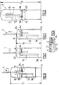
- the protection device 1 of Figures 10 to 14 is similar to the protection device of Figures 1 to 6 . It differs therefrom in that the peg 6 is subject to the action of a spring 34 which is urged laterally from the first longitudinal section 11 towards the second longitudinal section 12 of the running passageway 10.
- the support 3 comprises a deflection passage 35 arranged in such a way as to guide the said peg 6 laterally.
- the peg 6 arrives in the deflection passage 35 in which it is pushed by the spring 34 which relaxes.
- the spring 34 forms at least in part the first safety means, elastically deformable, preventing the peg 6 from returning from the said second section 12 to the said first section 11.
- the peg 6 is guided in the second longitudinal section 12 of the running passageway 10.
- the peg 6 is kept blocked against the proximal end 38 of the second longitudinal section 12 of the running passageway 10 by the thrust of the spring 34.
- the needle is perfectly covered by the sleeve.
- the injection device 1 is safe.
- the protection device 1 according to the invention allows an injection to be given in complete safety by virtue in particular of the fact that the sleeve 4 that protects the needle 2 does not rotate on itself at any time during the injection process and by virtue of the fact that this sleeve 4 deploys automatically at the end of the injection without any additional manual operation on the part of the user.
- the reliability of the protection device 1 according to the invention is increased by the reduced number of parts involved and their reduced relative movement with therefore enable to limit problems due to friction between moving parts.
Landscapes
- Health & Medical Sciences (AREA)
- Engineering & Computer Science (AREA)
- Heart & Thoracic Surgery (AREA)
- Vascular Medicine (AREA)
- Anesthesiology (AREA)
- Biomedical Technology (AREA)
- Hematology (AREA)
- Life Sciences & Earth Sciences (AREA)
- Animal Behavior & Ethology (AREA)
- General Health & Medical Sciences (AREA)
- Public Health (AREA)
- Veterinary Medicine (AREA)
- Environmental & Geological Engineering (AREA)
- Emergency Medicine (AREA)
- Infusion, Injection, And Reservoir Apparatuses (AREA)
Claims (20)
- Dispositif de protection (1) destiné à couvrir au moins partiellement l'aiguille (2) d'un dispositif d'injection, ledit dispositif de protection (1) comprenant au moins :- un support (3) pourvu d'un moyen de fixation (9) destiné à fixer ledit dispositif de protection (1) à un dispositif d'injection,- un manchon (4) comprenant une extrémité distale (15) destinée à venir en contact avec une surface d'injection et pourvu d'un orifice destiné à permettre le passage de ladite aiguille, ledit manchon (4) étant agencé de manière à pouvoir se déplacer axialement en translation par rapport audit support (3) depuis une première position dite position de stockage, dans laquelle l'extrémité distale dudit manchon (4) se trouve à une distance l1 dudit moyen de fixation, vers une deuxième position dite position d'injection, dans laquelle l'extrémité distale dudit manchon (4) se trouve à une distance l2 dudit moyen de fixation, et vers une troisième position dite position de protection, dans laquelle l'extrémité distale dudit manchon (4) se trouve à une distance l3 dudit moyen de fixation, lesdites distances l1 et l3 étant supérieures à ladite distance l2,- des premiers moyens de rappel (14) pour faire repasser ledit manchon (4) au moins de sa position d'injection à sa position de protection,- au moins un tenon (6), directement et au moins élastiquement, couplé longitudinalement audit support (3) ou audit manchon (4) et reçu dans un passage de déplacement (10) prévu respectivement dans ledit manchon (4) ou dans ledit support (3), ledit passage de déplacement (10) formant plus ou moins un U, dont les branches définissent respectivement une première section (11) prise par ledit tenon (6) lorsque ledit manchon (4) se déplace de sa position de stockage à sa position d'injection et une deuxième section (12) prise par ledit tenon (6) lorsque ledit manchon (4) passe de sa position d'injection à sa position de protection, ledit tenon (6) étant conçu pour être mobile latéralement,- des premiers moyens de sécurité (5, 21 ; 39, 34, 35), au moins une partie de ceux-ci étant élastiquement déformables, lesdits premiers moyens de sécurité (5, 21 ; 39, 36, 34, 35) étant agencés de manière à empêcher ledit tenon (6) de repasser de ladite deuxième section (12) à ladite première section (11), caractérisé en ce que ledit dispositif de protection (1) comprend au moins :- des moyens de guidage axial (29, 30) permettant de guider ledit manchon (4), agencés de manière à l'empêcher de pivoter axialement lorsqu'il se déplace axialement par rapport audit support (3) au moins de sa position d'injection à sa position de protection.
- Dispositif de protection (1) selon la revendication 1, caractérisé en ce que lesdits moyens de guidage axial (29, 30) sont agencés de manière à empêcher également ledit manchon (4) de pivoter axialement lorsqu'il se déplace axialement par rapport audit support (3) de sa position de stockage à sa position d'injection.
- Dispositif de protection (1) selon la revendication 1, caractérisé en ce que lesdits moyens de guidage axial (29, 30) comprennent des formes géométriques longitudinales plus ou moins complémentaires prévues respectivement sur ledit manchon (4) et sur ledit support (3) et agencées en vis-à-vis pour coopérer.
- Dispositif de protection (1) selon la revendication 1, caractérisé en ce que lesdites première et deuxième sections (11, 12) dudit passage de déplacement (10) sont reliées entre elles par une première région rétrécie (21, 36) définie par une languette flexible (39) définissant au moins partiellement lesdits premiers moyens de sécurité.
- Dispositif de protection (1) selon la revendication 1, caractérisé en ce que ledit tenon (6) est poussé latéralement depuis ladite première section vers ladite deuxième section par des deuxièmes moyens de rappel (34) définissant au moins partiellement lesdits premiers moyens de sécurité.
- Dispositif de protection (1) selon la revendication 1, caractérisé en ce que ledit support (3) ou, respectivement, ledit manchon (4) comprend au moins une patte (5) apte à dévier tangentiellement et portant ledit tenon (6).
- Dispositif de protection (1) selon la revendication 6, caractérisé en ce que ladite patte est agencée de façon à dévier tangentiellement de manière élastiquement déformable entre une position normale et au moins une position déviée contrainte, ladite patte (5) définissant au moins partiellement lesdits premiers moyens de sécurité.
- Dispositif de protection (1) selon la revendication 7, caractérisé en ce que ladite patte (5) se trouve dans une position normale ou, respectivement, dans une position déviée contrainte lorsque ledit tenon (6) est dans ladite première section (11), et ladite patte (5) se trouve dans la position déviée contrainte ou, respectivement, dans la position normale lorsque ledit tenon (6) est dans ladite deuxième section (12).
- Dispositif de protection (1) selon la revendication 1, caractérisé en ce que lesdites première et deuxième sections (11, 12) ont des longueurs différentes agencées de manière à délimiter lesdites positions de stockage et de protection de sorte que ladite distance l3 soit supérieure à ladite distance l1.
- Dispositif de protection (1) selon la revendication 1, caractérisé en ce que, en face dudit passage de déplacement (10) prévu sur ledit manchon (4) ou, respectivement, sur ledit support (3), ledit support (3) ou, respectivement, ledit manchon (4) comprend un passage de déviation (35) agencé de manière à guider ledit tenon (6) latéralement.
- Dispositif de protection (1) selon la revendication 1, caractérisé en ce qu'il comprend des deuxièmes moyens de sécurité (23, 33, 37, 34, 38) agencés de manière à bloquer ledit tenon (6) lorsque ledit manchon (4) se trouve dans ladite position de protection.
- Dispositif de protection (1) selon la revendication 11, caractérisé en ce que ladite deuxième section (12) dudit passage de déplacement (10) comprend une deuxième région rétrécie (23) définissant au moins partiellement lesdits deuxièmes moyens de sécurité.
- Dispositif de protection (1) selon la revendication 11, caractérisé en ce que ladite deuxième section (12) dudit passage de déplacement (10) comprend au moins un gradin (24) formant un cran d'arrêt pour ledit tenon (6) lorsque ledit manchon (4) se trouve dans ladite position de protection et définissant au moins partiellement lesdits deuxièmes moyens de sécurité.
- Dispositif de protection (1) selon la revendication 1 ou 10, caractérisé en ce que ledit passage de déplacement (10) et/ou ledit passage de déviation (35) est/sont formé(s) d'au moins un élément choisi dans le groupe comprenant une rainure, une fente, une nervure ou une combinaison de ces éléments.
- Dispositif de protection (1) selon la revendication 1 ou 5, caractérisé en ce que lesdits premiers et/ou deuxièmes moyens de rappel (14, 34) sont élastiquement déformables et choisis dans le groupe comprenant un ressort hélicoïdal, une lame élastique, un élément élastiquement déformable.
- Dispositif de protection (1) selon la revendication 1, caractérisé en ce que lesdits premiers moyens de rappel (14) sont agencés entre l'extrémité proximale dudit support (3) et l'extrémité distale dudit manchon (4).
- Dispositif de protection (1) selon la revendication 6, caractérisé en ce que ledit manchon (4) ou, respectivement, ledit support (3) comprend au moins une paroi d'arrêt (8) située en face de ladite patte (5) lorsque le dispositif (1) se trouve dans la position de protection, ladite paroi d'arrêt (8) étant agencée de manière à empêcher la déviation radiale de ladite patte (5) vers l'axe dudit dispositif de protection dans cette position de protection.
- Dispositif de protection (1) selon la revendication 1, caractérisé en ce que ledit support (3) est pourvu d'une aiguille d'injection (2).
- Dispositif d'injection (1) comprenant au moins une aiguille d'injection (2) et un réservoir de produit à injecter, caractérisé en ce qu'il comprend au moins un dispositif de protection (1) selon au moins l'une des revendications 1 à 18.
- Ensemble comprenant un dispositif de protection (1) selon l'une quelconque des revendications 1 à 18 et un emballage (26) pour ce dispositif, ledit emballage comprenant un corps cylindrique (27) et un capuchon (28), ledit corps cylindrique étant équipé sur sa paroi interne de moyens pour bloquer la rotation et la translation dudit dispositif à l'intérieur dudit emballage.
Applications Claiming Priority (2)
| Application Number | Priority Date | Filing Date | Title |
|---|---|---|---|
| FR0503965A FR2884723B1 (fr) | 2005-04-20 | 2005-04-20 | Dispositif de protection d'un dispositif d'injection |
| PCT/IB2006/001738 WO2006131832A1 (fr) | 2005-04-20 | 2006-04-20 | Dispositif de protection pour proteger une aiguille de seringue |
Publications (2)
| Publication Number | Publication Date |
|---|---|
| EP1888151A1 EP1888151A1 (fr) | 2008-02-20 |
| EP1888151B1 true EP1888151B1 (fr) | 2018-08-22 |
Family
ID=34955189
Family Applications (1)
| Application Number | Title | Priority Date | Filing Date |
|---|---|---|---|
| EP06779771.2A Expired - Lifetime EP1888151B1 (fr) | 2005-04-20 | 2006-04-20 | Dispositif de protection pour proteger une aiguille de seringue |
Country Status (6)
| Country | Link |
|---|---|
| US (3) | US9457157B2 (fr) |
| EP (1) | EP1888151B1 (fr) |
| JP (1) | JP4981030B2 (fr) |
| ES (1) | ES2693425T3 (fr) |
| FR (1) | FR2884723B1 (fr) |
| WO (1) | WO2006131832A1 (fr) |
Families Citing this family (74)
| Publication number | Priority date | Publication date | Assignee | Title |
|---|---|---|---|---|
| US7654986B2 (en) | 2002-07-03 | 2010-02-02 | Novo Nordisk A/S | Needle mounting system and a method for mounting a needle assembly |
| US20090204076A1 (en) * | 2003-02-03 | 2009-08-13 | Barry Peter Liversidge | Medical Injector |
| GB0414054D0 (en) | 2004-06-23 | 2004-07-28 | Owen Mumford Ltd | Improvements relating to automatic injection devices |
| TWI498137B (zh) | 2006-06-30 | 2015-09-01 | Abbvie Biotechnology Ltd | 自動注射裝置 |
| GB2445437B (en) * | 2007-07-06 | 2008-11-26 | Applied Medical Technology Ltd | Cannula insertion device |
| USD675316S1 (en) | 2007-08-22 | 2013-01-29 | Novo Nordisk A/S | Needle hub |
| JP5451638B2 (ja) * | 2008-01-15 | 2014-03-26 | ベクトン・ディキンソン・アンド・カンパニー | ペン針組立品を備える医療用注射器 |
| GB0802351D0 (en) * | 2008-02-08 | 2008-03-12 | Owen Mumford Ltd | Injection devices |
| FR2930160B1 (fr) * | 2008-04-16 | 2011-05-13 | Becton Dickinson France | Ensemble de protection d'aiguille. |
| ES2914825T3 (es) * | 2008-08-15 | 2022-06-16 | Becton Dickinson Co | Conjunto de aguja de pluma de seguridad |
| MX2011011541A (es) | 2009-04-29 | 2012-02-28 | Abbott Biotech Ltd | Dispositivo de inyeccion automatico. |
| GB0912347D0 (en) | 2009-07-16 | 2009-08-26 | Shapland Howard | Universal adaptor |
| US9233213B2 (en) | 2009-10-16 | 2016-01-12 | Janssen Biotech, Inc. | Palm activated drug delivery device |
| WO2011047298A2 (fr) | 2009-10-16 | 2011-04-21 | Centocor Ortho Biotech Inc. | Dispositif d'administration de médicament activé par la paume |
| US8663174B2 (en) * | 2009-11-13 | 2014-03-04 | Becton, Dickinson And Company | Hub assembly having a hidden needle for a drug delivery pen |
| US8480646B2 (en) | 2009-11-20 | 2013-07-09 | Carmel Pharma Ab | Medical device connector |
| JP5623541B2 (ja) * | 2009-11-20 | 2014-11-12 | カルメル ファルマ アクチボラゲット | 医療装置コネクタ |
| US8758301B2 (en) * | 2009-12-15 | 2014-06-24 | Abbvie Biotechnology Ltd | Firing button for automatic injection device |
| EP2515973B1 (fr) | 2009-12-23 | 2018-02-21 | Tecpharma Licensing AG | Dispositif d'injection comportant une gaine de protection d'aiguille |
| WO2011076281A1 (fr) * | 2009-12-23 | 2011-06-30 | Tecpharma Licensing Ag | Dispositif pour retirer un capuchon de protection d'aiguille d'une aiguille |
| WO2011117287A1 (fr) * | 2010-03-25 | 2011-09-29 | Sanofi-Aventis Deutschland Gmbh | Module médicamenteux avec entrée en prise automatique du réservoir |
| KR101850687B1 (ko) | 2010-04-21 | 2018-04-20 | 애브비 바이오테크놀로지 리미티드 | 치료제의 제어된 전달을 위한 착용형 자동 주사 디바이스 |
| PL2588168T3 (pl) * | 2010-07-02 | 2015-08-31 | Sanofi Aventis Deutschland | Urządzenie zabezpieczające do wstępnie napełnionej strzykawki oraz urządzenie iniekcyjne |
| MY166395A (en) * | 2010-07-02 | 2018-06-25 | Sanofi Aventis Deutschland | Safety device for a pre-filled syringe and injection device |
| RU2572738C2 (ru) | 2010-07-02 | 2016-01-20 | Санофи-Авентис Дойчланд Гмбх | Защитное устройство для предварительно заполненного шприца и инъекционное устройство |
| DK2588165T3 (da) | 2010-07-02 | 2020-09-14 | Sanofi Aventis Deutschland | Sikkerhedsanordning til en fyldt injektionssprøjte, injektionsanordning og injektionskit |
| WO2012000837A1 (fr) * | 2010-07-02 | 2012-01-05 | Sanofi-Aventis Deutschland Gmbh | Dispositif d'injection doté d'un protecteur d'aiguille |
| EP2588162B1 (fr) * | 2010-07-02 | 2020-01-01 | Sanofi-Aventis Deutschland GmbH | Dispositif de sécurité pour seringue pré-remplie et dispositif d'injection |
| EP2661293B1 (fr) * | 2011-01-04 | 2019-01-23 | Sanofi-Aventis Deutschland GmbH | Dispositif de sécurité pour seringue pré-remplie et dispositif d'injection |
| EP3744372B1 (fr) * | 2011-01-04 | 2023-04-26 | Sanofi-Aventis Deutschland GmbH | Dispositif de sécurité pour seringue préremplie et dispositif d'injection |
| MX336571B (es) | 2011-01-24 | 2016-01-25 | Elcam Medical Agricultural Cooperative Ass Ltd | Inyector. |
| MX388000B (es) | 2011-01-24 | 2025-03-19 | Abbvie Biotechnology Ltd | Separación de protectores de aguja de jeringas y dispositivos de inyección automáticos. |
| RU2602039C2 (ru) | 2011-01-24 | 2016-11-10 | Эббви Байотекнолоджи Лтд. | Автоматические инъекционные устройства, имеющие наформованные поверхности захвата |
| EP2942072B1 (fr) * | 2011-05-18 | 2018-11-28 | Becton, Dickinson and Company | Injecteur à usage unique de faible coût |
| CN103732278B (zh) * | 2011-06-17 | 2016-02-17 | 赛诺菲-安万特德国有限公司 | 用于给药装置的药筒保持器组件 |
| EP2578257A1 (fr) * | 2011-10-06 | 2013-04-10 | Sanofi-Aventis Deutschland GmbH | Dispositif de sécurité d'aiguille |
| US10004854B2 (en) | 2012-03-07 | 2018-06-26 | West Pharmaceutical Services, Inc. | Low radial profile needle safety device |
| WO2013134465A1 (fr) | 2012-03-07 | 2013-09-12 | West Pharmaceutical Services, Inc. | Dispositif de sécurité d'aiguille à faible profil radial |
| SK500122012A3 (sk) * | 2012-03-28 | 2013-10-02 | Marian Buday | Single-use safety syringe |
| JP6293126B2 (ja) * | 2012-05-25 | 2018-03-14 | アプター フランス エスアーエス | 自己注射器 |
| US9662447B2 (en) * | 2012-05-25 | 2017-05-30 | Aptar France Sas | Autoinjector |
| EP2687252A1 (fr) * | 2012-07-17 | 2014-01-22 | Sanofi-Aventis Deutschland GmbH | Dispositif d'administration de médicaments |
| WO2014056635A1 (fr) * | 2012-10-08 | 2014-04-17 | Tecpharma Licensing Ag | Dispositif d'injection pourvu d'un moyen de commande de dose |
| WO2014164823A1 (fr) * | 2013-03-11 | 2014-10-09 | Auerbach, Judith | Système de sécurité pour un dispositif de retenue d'aiguille |
| USD757256S1 (en) * | 2013-03-15 | 2016-05-24 | Neogen Corporation | Sampler |
| JP6211309B2 (ja) * | 2013-05-31 | 2017-10-11 | 株式会社ダイセル | 注射器 |
| EP3034118B1 (fr) * | 2013-08-14 | 2019-09-18 | Terumo Kabushiki Kaisha | Seringue |
| US9937299B2 (en) | 2013-09-26 | 2018-04-10 | Becton, Dickinson And Company | Adjustable penetration depth syringe |
| FR3013601B1 (fr) * | 2013-11-25 | 2017-08-11 | Aptar France Sas | Autoinjecteur. |
| GB201407682D0 (en) * | 2014-05-01 | 2014-06-18 | New Injection Systems Ltd | Needle Safety Shield |
| GB2529390A (en) | 2014-08-12 | 2016-02-24 | Owen Mumford Ltd | Needle assembly |
| CN104307072A (zh) * | 2014-10-29 | 2015-01-28 | 杭州普昂医疗科技有限公司 | 安全式胰岛素笔针 |
| EP3251715B1 (fr) | 2015-01-30 | 2020-01-29 | Terumo Kabushiki Kaisha | Protecteur et ensemble d'instrument médical |
| ES2708182T3 (es) * | 2015-06-15 | 2019-04-09 | Gerresheimer Regensburg Gmbh | Cuerpo de jeringa |
| JP6118848B2 (ja) * | 2015-07-14 | 2017-04-19 | ベクトン・ディキンソン・アンド・カンパニーBecton, Dickinson And Company | 低コストの単回使用注射器 |
| WO2017164356A1 (fr) * | 2016-03-25 | 2017-09-28 | テルモ株式会社 | Ensemble de dispositif de protection et d'instrument médical |
| FR3056916B1 (fr) * | 2016-10-04 | 2018-11-09 | Aptar France Sas | Dispositif d'injection manuelle. |
| US11103651B2 (en) | 2016-12-13 | 2021-08-31 | Beckon, Dickinson and Company | Safety needle devices |
| US11147910B2 (en) | 2016-12-12 | 2021-10-19 | Becton, Dickinson And Company | Packaging for safety needle |
| US11173253B2 (en) | 2016-12-12 | 2021-11-16 | Becton, Dickinson And Company | Packaging for safety needle |
| US10792438B2 (en) | 2016-12-13 | 2020-10-06 | Becton, Dickinson And Company | Safety needle devices |
| US10661026B2 (en) * | 2016-12-13 | 2020-05-26 | Becton, Dickinson And Company | Safety needle device |
| US10589036B2 (en) | 2016-12-13 | 2020-03-17 | Becton, Dickinson And Company | Safety needle device |
| EP3406283B1 (fr) | 2017-05-26 | 2024-11-20 | Embecta Corp. | Aiguille de stylet |
| EP3659654B1 (fr) | 2018-03-16 | 2022-05-25 | Terumo Kabushiki Kaisha | Ensemble aiguille |
| CN108543169B (zh) | 2018-05-16 | 2023-12-01 | 普昂(杭州)医疗科技股份有限公司 | 一种安全式胰岛素笔针 |
| EP3741631B1 (fr) * | 2019-05-20 | 2022-04-06 | Fico Transpar, S.A. | Dispositif de lavage télescopique |
| FR3097425A1 (fr) * | 2019-06-24 | 2020-12-25 | Anecova S.A. | Dispositif de protection pour dispositif médical |
| CA3180013A1 (fr) * | 2020-04-15 | 2021-10-21 | Bayer Healthcare Llc | Systeme de seringue preremplie et procede |
| EP3978051A1 (fr) * | 2020-10-02 | 2022-04-06 | Becton, Dickinson and Company | Seringue de sécurité |
| IT202200003977A1 (it) * | 2022-03-03 | 2023-09-03 | Ferrotto Design S R L | Siringa ipodermica sicura |
| CN117414503A (zh) * | 2023-08-28 | 2024-01-19 | 梵颖(上海)生物科技有限公司 | 一种注射器保护装置及安全注射器 |
| USD1109322S1 (en) | 2023-10-02 | 2026-01-13 | Regeneron Pharmaceuticals, Inc. | Drug-delivery device |
| USD1108627S1 (en) | 2023-10-02 | 2026-01-06 | Regeneron Pharmaceuticals, Inc. | Drug-delivery device |
Family Cites Families (25)
| Publication number | Priority date | Publication date | Assignee | Title |
|---|---|---|---|---|
| ATE60239T1 (de) * | 1986-11-19 | 1991-02-15 | Sterimatic Holdings Ltd | Injektionsvorrichtungen. |
| US4932940A (en) * | 1988-06-06 | 1990-06-12 | Walker Cedric F | Needle guard device |
| US4927417A (en) * | 1988-07-07 | 1990-05-22 | Schneider Medical Technologies, Inc. | Safety sleeve adapter |
| US4917673A (en) * | 1988-10-31 | 1990-04-17 | Coplin Allan J | Assembly for the protection against inadvertent puncture by medical needles |
| US4966592A (en) * | 1989-05-05 | 1990-10-30 | Burns Cameron A | Protective sleeve for hypodermic needle |
| WO1991011212A1 (fr) * | 1990-02-02 | 1991-08-08 | Gerard Philip Gilliland | Dispositif a tranchant retractable |
| US5254099A (en) * | 1992-03-10 | 1993-10-19 | Injectimed. Inc. | Hard cover for pre-cocking protected injection apparatus |
| US5267972A (en) * | 1992-07-20 | 1993-12-07 | Anderson Wayne W | Hypodermic syringe with needle guard |
| US5242401A (en) * | 1992-10-09 | 1993-09-07 | Colsky Andrew E | Disposable needle head assembly |
| US5295975A (en) * | 1992-10-28 | 1994-03-22 | Lockwood Jr Hanford N | Hypodermic needle safety device with sliding outer cover |
| US5411487A (en) * | 1992-12-07 | 1995-05-02 | Castagna; John F. | Hypodermic syringe with automatic needle cover |
| US5984899A (en) * | 1993-02-11 | 1999-11-16 | Beech Medical Products, Inc. | Needle protector device having a lockable protective cover which is unlockable during actuation |
| US5688241A (en) * | 1996-04-15 | 1997-11-18 | Asbaghi; Hooman Ali | Automatic non-reusable needle guard |
| IE970782A1 (en) * | 1997-10-22 | 1999-05-05 | Elan Corp | An improved automatic syringe |
| US20020004652A1 (en) * | 1999-06-18 | 2002-01-10 | Asbaghi Hooman A. | Protective device for a fillable injection syringe |
| US6926696B2 (en) * | 1999-12-23 | 2005-08-09 | Owais Mohammed | Hypodermic syringe needle assembly and method of making the same |
| US6547764B2 (en) * | 2000-05-31 | 2003-04-15 | Novo Nordisk A/S | Double pointed injection needle |
| US6485469B1 (en) * | 2001-01-10 | 2002-11-26 | Sherwood Services Ag | Shielded dental safety needle |
| JP3725842B2 (ja) * | 2002-03-15 | 2005-12-14 | カルソニックカンセイ株式会社 | パイプ曲げ加工装置およびパイプ曲げ加工方法 |
| US6702784B1 (en) * | 2002-11-01 | 2004-03-09 | Ross David Sheckler | Limited injection cycle safety syringe |
| US6884237B2 (en) * | 2002-12-10 | 2005-04-26 | Inviro Medical Devices, Inc. | Position guide for a needle guard |
| US6846302B2 (en) * | 2002-12-31 | 2005-01-25 | Teva Medical Ltd. | Needle protector device |
| US6926697B2 (en) * | 2003-05-13 | 2005-08-09 | Robert Malenchek | Adaptor for converting a non-safety syringe into a safety syringe |
| US7497847B2 (en) * | 2003-11-03 | 2009-03-03 | Becton, Dickinson And Company | Safety shield system for a syringe |
| GB0327136D0 (en) * | 2003-11-21 | 2003-12-24 | Nmt Group Plc | Safety needle |
-
2005
- 2005-04-20 FR FR0503965A patent/FR2884723B1/fr not_active Expired - Lifetime
-
2006
- 2006-04-20 WO PCT/IB2006/001738 patent/WO2006131832A1/fr not_active Ceased
- 2006-04-20 ES ES06779771.2T patent/ES2693425T3/es not_active Expired - Lifetime
- 2006-04-20 JP JP2008507198A patent/JP4981030B2/ja not_active Expired - Lifetime
- 2006-04-20 US US11/912,257 patent/US9457157B2/en active Active
- 2006-04-20 EP EP06779771.2A patent/EP1888151B1/fr not_active Expired - Lifetime
-
2016
- 2016-08-30 US US15/251,469 patent/US10420900B2/en active Active
-
2019
- 2019-08-02 US US16/530,400 patent/US11744958B2/en active Active
Non-Patent Citations (1)
| Title |
|---|
| None * |
Also Published As
| Publication number | Publication date |
|---|---|
| JP4981030B2 (ja) | 2012-07-18 |
| US11744958B2 (en) | 2023-09-05 |
| WO2006131832A1 (fr) | 2006-12-14 |
| US10420900B2 (en) | 2019-09-24 |
| US9457157B2 (en) | 2016-10-04 |
| FR2884723B1 (fr) | 2008-03-14 |
| US20190351151A1 (en) | 2019-11-21 |
| FR2884723A1 (fr) | 2006-10-27 |
| JP2008536598A (ja) | 2008-09-11 |
| US20090024093A1 (en) | 2009-01-22 |
| US20160367765A1 (en) | 2016-12-22 |
| EP1888151A1 (fr) | 2008-02-20 |
| ES2693425T3 (es) | 2018-12-11 |
Similar Documents
| Publication | Publication Date | Title |
|---|---|---|
| US11744958B2 (en) | Protection device for protecting an injection needle | |
| US12527916B2 (en) | Auto-injector | |
| US20230201483A1 (en) | Safety needle device | |
| EP3441096B1 (fr) | Dispositif de sécurité pour seringue préremplie et dispositif d'injection | |
| AU2010260568B2 (en) | Safety pen needle device | |
| JP6138129B2 (ja) | 注射装置 | |
| EP2468328A1 (fr) | Auto-injecteur |
Legal Events
| Date | Code | Title | Description |
|---|---|---|---|
| PUAI | Public reference made under article 153(3) epc to a published international application that has entered the european phase |
Free format text: ORIGINAL CODE: 0009012 |
|
| 17P | Request for examination filed |
Effective date: 20071023 |
|
| AK | Designated contracting states |
Kind code of ref document: A1 Designated state(s): AT BE BG CH CY CZ DE DK EE ES FI FR GB GR HU IE IS IT LI LT LU LV MC NL PL PT RO SE SI SK TR |
|
| DAX | Request for extension of the european patent (deleted) | ||
| 17Q | First examination report despatched |
Effective date: 20160523 |
|
| STAA | Information on the status of an ep patent application or granted ep patent |
Free format text: STATUS: EXAMINATION IS IN PROGRESS |
|
| REG | Reference to a national code |
Ref country code: DE Ref legal event code: R079 Ref document number: 602006056154 Country of ref document: DE Free format text: PREVIOUS MAIN CLASS: A61M0005320000 Ipc: A61M0005360000 |
|
| RIC1 | Information provided on ipc code assigned before grant |
Ipc: A61M 5/32 20060101ALI20180110BHEP Ipc: A61M 5/36 20060101AFI20180110BHEP |
|
| GRAP | Despatch of communication of intention to grant a patent |
Free format text: ORIGINAL CODE: EPIDOSNIGR1 |
|
| STAA | Information on the status of an ep patent application or granted ep patent |
Free format text: STATUS: GRANT OF PATENT IS INTENDED |
|
| INTG | Intention to grant announced |
Effective date: 20180312 |
|
| RAP1 | Party data changed (applicant data changed or rights of an application transferred) |
Owner name: BECTON DICKINSON FRANCE |
|
| GRAS | Grant fee paid |
Free format text: ORIGINAL CODE: EPIDOSNIGR3 |
|
| GRAA | (expected) grant |
Free format text: ORIGINAL CODE: 0009210 |
|
| STAA | Information on the status of an ep patent application or granted ep patent |
Free format text: STATUS: THE PATENT HAS BEEN GRANTED |
|
| AK | Designated contracting states |
Kind code of ref document: B1 Designated state(s): AT BE BG CH CY CZ DE DK EE ES FI FR GB GR HU IE IS IT LI LT LU LV MC NL PL PT RO SE SI SK TR |
|
| REG | Reference to a national code |
Ref country code: GB Ref legal event code: FG4D |
|
| REG | Reference to a national code |
Ref country code: CH Ref legal event code: EP |
|
| REG | Reference to a national code |
Ref country code: AT Ref legal event code: REF Ref document number: 1031735 Country of ref document: AT Kind code of ref document: T Effective date: 20180915 |
|
| REG | Reference to a national code |
Ref country code: IE Ref legal event code: FG4D |
|
| REG | Reference to a national code |
Ref country code: DE Ref legal event code: R096 Ref document number: 602006056154 Country of ref document: DE |
|
| REG | Reference to a national code |
Ref country code: ES Ref legal event code: FG2A Ref document number: 2693425 Country of ref document: ES Kind code of ref document: T3 Effective date: 20181211 |
|
| REG | Reference to a national code |
Ref country code: NL Ref legal event code: MP Effective date: 20180822 |
|
| REG | Reference to a national code |
Ref country code: LT Ref legal event code: MG4D |
|
| PG25 | Lapsed in a contracting state [announced via postgrant information from national office to epo] |
Ref country code: NL Free format text: LAPSE BECAUSE OF FAILURE TO SUBMIT A TRANSLATION OF THE DESCRIPTION OR TO PAY THE FEE WITHIN THE PRESCRIBED TIME-LIMIT Effective date: 20180822 Ref country code: IS Free format text: LAPSE BECAUSE OF FAILURE TO SUBMIT A TRANSLATION OF THE DESCRIPTION OR TO PAY THE FEE WITHIN THE PRESCRIBED TIME-LIMIT Effective date: 20181222 Ref country code: SE Free format text: LAPSE BECAUSE OF FAILURE TO SUBMIT A TRANSLATION OF THE DESCRIPTION OR TO PAY THE FEE WITHIN THE PRESCRIBED TIME-LIMIT Effective date: 20180822 Ref country code: BG Free format text: LAPSE BECAUSE OF FAILURE TO SUBMIT A TRANSLATION OF THE DESCRIPTION OR TO PAY THE FEE WITHIN THE PRESCRIBED TIME-LIMIT Effective date: 20181122 Ref country code: LT Free format text: LAPSE BECAUSE OF FAILURE TO SUBMIT A TRANSLATION OF THE DESCRIPTION OR TO PAY THE FEE WITHIN THE PRESCRIBED TIME-LIMIT Effective date: 20180822 Ref country code: FI Free format text: LAPSE BECAUSE OF FAILURE TO SUBMIT A TRANSLATION OF THE DESCRIPTION OR TO PAY THE FEE WITHIN THE PRESCRIBED TIME-LIMIT Effective date: 20180822 |
|
| REG | Reference to a national code |
Ref country code: AT Ref legal event code: MK05 Ref document number: 1031735 Country of ref document: AT Kind code of ref document: T Effective date: 20180822 |
|
| PG25 | Lapsed in a contracting state [announced via postgrant information from national office to epo] |
Ref country code: LV Free format text: LAPSE BECAUSE OF FAILURE TO SUBMIT A TRANSLATION OF THE DESCRIPTION OR TO PAY THE FEE WITHIN THE PRESCRIBED TIME-LIMIT Effective date: 20180822 |
|
| PG25 | Lapsed in a contracting state [announced via postgrant information from national office to epo] |
Ref country code: RO Free format text: LAPSE BECAUSE OF FAILURE TO SUBMIT A TRANSLATION OF THE DESCRIPTION OR TO PAY THE FEE WITHIN THE PRESCRIBED TIME-LIMIT Effective date: 20180822 Ref country code: EE Free format text: LAPSE BECAUSE OF FAILURE TO SUBMIT A TRANSLATION OF THE DESCRIPTION OR TO PAY THE FEE WITHIN THE PRESCRIBED TIME-LIMIT Effective date: 20180822 Ref country code: AT Free format text: LAPSE BECAUSE OF FAILURE TO SUBMIT A TRANSLATION OF THE DESCRIPTION OR TO PAY THE FEE WITHIN THE PRESCRIBED TIME-LIMIT Effective date: 20180822 Ref country code: PL Free format text: LAPSE BECAUSE OF FAILURE TO SUBMIT A TRANSLATION OF THE DESCRIPTION OR TO PAY THE FEE WITHIN THE PRESCRIBED TIME-LIMIT Effective date: 20180822 Ref country code: CZ Free format text: LAPSE BECAUSE OF FAILURE TO SUBMIT A TRANSLATION OF THE DESCRIPTION OR TO PAY THE FEE WITHIN THE PRESCRIBED TIME-LIMIT Effective date: 20180822 |
|
| REG | Reference to a national code |
Ref country code: DE Ref legal event code: R097 Ref document number: 602006056154 Country of ref document: DE |
|
| PG25 | Lapsed in a contracting state [announced via postgrant information from national office to epo] |
Ref country code: SK Free format text: LAPSE BECAUSE OF FAILURE TO SUBMIT A TRANSLATION OF THE DESCRIPTION OR TO PAY THE FEE WITHIN THE PRESCRIBED TIME-LIMIT Effective date: 20180822 Ref country code: DK Free format text: LAPSE BECAUSE OF FAILURE TO SUBMIT A TRANSLATION OF THE DESCRIPTION OR TO PAY THE FEE WITHIN THE PRESCRIBED TIME-LIMIT Effective date: 20180822 |
|
| PLBE | No opposition filed within time limit |
Free format text: ORIGINAL CODE: 0009261 |
|
| STAA | Information on the status of an ep patent application or granted ep patent |
Free format text: STATUS: NO OPPOSITION FILED WITHIN TIME LIMIT |
|
| 26N | No opposition filed |
Effective date: 20190523 |
|
| PG25 | Lapsed in a contracting state [announced via postgrant information from national office to epo] |
Ref country code: SI Free format text: LAPSE BECAUSE OF FAILURE TO SUBMIT A TRANSLATION OF THE DESCRIPTION OR TO PAY THE FEE WITHIN THE PRESCRIBED TIME-LIMIT Effective date: 20180822 |
|
| REG | Reference to a national code |
Ref country code: CH Ref legal event code: PL |
|
| REG | Reference to a national code |
Ref country code: BE Ref legal event code: MM Effective date: 20190430 |
|
| PG25 | Lapsed in a contracting state [announced via postgrant information from national office to epo] |
Ref country code: MC Free format text: LAPSE BECAUSE OF FAILURE TO SUBMIT A TRANSLATION OF THE DESCRIPTION OR TO PAY THE FEE WITHIN THE PRESCRIBED TIME-LIMIT Effective date: 20180822 Ref country code: LU Free format text: LAPSE BECAUSE OF NON-PAYMENT OF DUE FEES Effective date: 20190420 |
|
| PG25 | Lapsed in a contracting state [announced via postgrant information from national office to epo] |
Ref country code: LI Free format text: LAPSE BECAUSE OF NON-PAYMENT OF DUE FEES Effective date: 20190430 Ref country code: CH Free format text: LAPSE BECAUSE OF NON-PAYMENT OF DUE FEES Effective date: 20190430 |
|
| PG25 | Lapsed in a contracting state [announced via postgrant information from national office to epo] |
Ref country code: BE Free format text: LAPSE BECAUSE OF NON-PAYMENT OF DUE FEES Effective date: 20190430 |
|
| PG25 | Lapsed in a contracting state [announced via postgrant information from national office to epo] |
Ref country code: TR Free format text: LAPSE BECAUSE OF FAILURE TO SUBMIT A TRANSLATION OF THE DESCRIPTION OR TO PAY THE FEE WITHIN THE PRESCRIBED TIME-LIMIT Effective date: 20180822 |
|
| PG25 | Lapsed in a contracting state [announced via postgrant information from national office to epo] |
Ref country code: IE Free format text: LAPSE BECAUSE OF NON-PAYMENT OF DUE FEES Effective date: 20190420 |
|
| PG25 | Lapsed in a contracting state [announced via postgrant information from national office to epo] |
Ref country code: PT Free format text: LAPSE BECAUSE OF FAILURE TO SUBMIT A TRANSLATION OF THE DESCRIPTION OR TO PAY THE FEE WITHIN THE PRESCRIBED TIME-LIMIT Effective date: 20181222 |
|
| PG25 | Lapsed in a contracting state [announced via postgrant information from national office to epo] |
Ref country code: CY Free format text: LAPSE BECAUSE OF FAILURE TO SUBMIT A TRANSLATION OF THE DESCRIPTION OR TO PAY THE FEE WITHIN THE PRESCRIBED TIME-LIMIT Effective date: 20180822 |
|
| PG25 | Lapsed in a contracting state [announced via postgrant information from national office to epo] |
Ref country code: GR Free format text: LAPSE BECAUSE OF FAILURE TO SUBMIT A TRANSLATION OF THE DESCRIPTION OR TO PAY THE FEE WITHIN THE PRESCRIBED TIME-LIMIT Effective date: 20180822 |
|
| PG25 | Lapsed in a contracting state [announced via postgrant information from national office to epo] |
Ref country code: HU Free format text: LAPSE BECAUSE OF FAILURE TO SUBMIT A TRANSLATION OF THE DESCRIPTION OR TO PAY THE FEE WITHIN THE PRESCRIBED TIME-LIMIT; INVALID AB INITIO Effective date: 20060420 |
|
| PGFP | Annual fee paid to national office [announced via postgrant information from national office to epo] |
Ref country code: FR Payment date: 20230321 Year of fee payment: 18 |
|
| PG25 | Lapsed in a contracting state [announced via postgrant information from national office to epo] |
Ref country code: FR Free format text: LAPSE BECAUSE OF NON-PAYMENT OF DUE FEES Effective date: 20240430 |
|
| PG25 | Lapsed in a contracting state [announced via postgrant information from national office to epo] |
Ref country code: FR Free format text: LAPSE BECAUSE OF NON-PAYMENT OF DUE FEES Effective date: 20240430 |
|
| PGFP | Annual fee paid to national office [announced via postgrant information from national office to epo] |
Ref country code: IT Payment date: 20250319 Year of fee payment: 20 Ref country code: GB Payment date: 20250319 Year of fee payment: 20 |
|
| PGFP | Annual fee paid to national office [announced via postgrant information from national office to epo] |
Ref country code: DE Payment date: 20250319 Year of fee payment: 20 |
|
| PGFP | Annual fee paid to national office [announced via postgrant information from national office to epo] |
Ref country code: ES Payment date: 20250502 Year of fee payment: 20 |
|
| REG | Reference to a national code |
Ref country code: DE Ref legal event code: R071 Ref document number: 602006056154 Country of ref document: DE |
|
| REG | Reference to a national code |
Ref country code: ES Ref legal event code: FD2A Effective date: 20260504 |