EP1888366B1 - Fahrzeugsitz, insbesondere sitzbank für ein kraftfahrzeug - Google Patents
Fahrzeugsitz, insbesondere sitzbank für ein kraftfahrzeug Download PDFInfo
- Publication number
- EP1888366B1 EP1888366B1 EP06724594A EP06724594A EP1888366B1 EP 1888366 B1 EP1888366 B1 EP 1888366B1 EP 06724594 A EP06724594 A EP 06724594A EP 06724594 A EP06724594 A EP 06724594A EP 1888366 B1 EP1888366 B1 EP 1888366B1
- Authority
- EP
- European Patent Office
- Prior art keywords
- vehicle seat
- vehicle
- coupling jaw
- mount
- mounting
- Prior art date
- Legal status (The legal status is an assumption and is not a legal conclusion. Google has not performed a legal analysis and makes no representation as to the accuracy of the status listed.)
- Expired - Lifetime
Links
Images



Classifications
-
- B—PERFORMING OPERATIONS; TRANSPORTING
- B60—VEHICLES IN GENERAL
- B60N—SEATS SPECIALLY ADAPTED FOR VEHICLES; VEHICLE PASSENGER ACCOMMODATION NOT OTHERWISE PROVIDED FOR
- B60N2/00—Seats specially adapted for vehicles; Arrangement or mounting of seats in vehicles
- B60N2/005—Arrangement or mounting of seats in vehicles, e.g. dismountable auxiliary seats
- B60N2/015—Attaching seats directly to vehicle chassis
- B60N2/01508—Attaching seats directly to vehicle chassis using quick release attachments
- B60N2/01516—Attaching seats directly to vehicle chassis using quick release attachments with locking mechanisms
- B60N2/01583—Attaching seats directly to vehicle chassis using quick release attachments with locking mechanisms locking on transversal elements on the vehicle floor or rail, e.g. transversal rods
-
- B—PERFORMING OPERATIONS; TRANSPORTING
- B60—VEHICLES IN GENERAL
- B60N—SEATS SPECIALLY ADAPTED FOR VEHICLES; VEHICLE PASSENGER ACCOMMODATION NOT OTHERWISE PROVIDED FOR
- B60N2/00—Seats specially adapted for vehicles; Arrangement or mounting of seats in vehicles
- B60N2/24—Seats specially adapted for vehicles; Arrangement or mounting of seats in vehicles for particular purposes or particular vehicles
- B60N2/30—Non-dismountable or dismountable seats storable in a non-use position, e.g. foldable spare seats
- B60N2/3002—Non-dismountable or dismountable seats storable in a non-use position, e.g. foldable spare seats back-rest movements
- B60N2/3004—Non-dismountable or dismountable seats storable in a non-use position, e.g. foldable spare seats back-rest movements by rotation only
- B60N2/3009—Non-dismountable or dismountable seats storable in a non-use position, e.g. foldable spare seats back-rest movements by rotation only about transversal axis
- B60N2/3011—Non-dismountable or dismountable seats storable in a non-use position, e.g. foldable spare seats back-rest movements by rotation only about transversal axis the back-rest being hinged on the cushion, e.g. "portefeuille movement"
-
- B—PERFORMING OPERATIONS; TRANSPORTING
- B60—VEHICLES IN GENERAL
- B60N—SEATS SPECIALLY ADAPTED FOR VEHICLES; VEHICLE PASSENGER ACCOMMODATION NOT OTHERWISE PROVIDED FOR
- B60N2/00—Seats specially adapted for vehicles; Arrangement or mounting of seats in vehicles
- B60N2/24—Seats specially adapted for vehicles; Arrangement or mounting of seats in vehicles for particular purposes or particular vehicles
- B60N2/30—Non-dismountable or dismountable seats storable in a non-use position, e.g. foldable spare seats
- B60N2/3038—Cushion movements
- B60N2/304—Cushion movements by rotation only
- B60N2/3045—Cushion movements by rotation only about transversal axis
- B60N2/305—Cushion movements by rotation only about transversal axis the cushion being hinged on the vehicle frame
-
- B—PERFORMING OPERATIONS; TRANSPORTING
- B60—VEHICLES IN GENERAL
- B60N—SEATS SPECIALLY ADAPTED FOR VEHICLES; VEHICLE PASSENGER ACCOMMODATION NOT OTHERWISE PROVIDED FOR
- B60N2205/00—General mechanical or structural details
- B60N2205/20—Measures for elimination or compensation of play or backlash
Definitions
- the invention relates to a vehicle seat, in particular a seat for a motor vehicle, which is anchored by means of at least one capture jaws releasably secured to the vehicle floor, with means for compensating tolerances between jaw and recording, wherein the recording comprises a horizontal, transverse to the sitting direction bolts which is arranged in a trough-like holder, and wherein the means are particularly suitable for compensating for tolerances in the vertical direction and include spring means which can be pressed against the bolt during assembly of the vehicle seat from the catching mouth.
- a vehicle seat of the type mentioned is in the utility model DE 200 06 691 U1 disclosed.
- the vehicle seat is equipped with swiveling rotary traps, which are provided for gripping bolts fastened to the vehicle floor.
- a safety device has a cam acting on the rotary latch, which is actuated by a spring-loaded or spring-like control element as soon as it comes into contact with the bolt.
- the mechanism is suitable for a self-adjusting tolerance and clearance compensation to bring the position of the bolt. In the Y direction of the vehicle, the bolt can also be damped by rubber elements.
- a similar device is known from the patent US 6,629,710 B1 known.
- EP 1 160 121 A1 is a rotary latch lock for the lateral locking of a pivotable backrest to the vehicle body is known in which in the recess of the rotary latch, a damping element is arranged.
- the publication DE 199 16 422 A1 describes a rotary latch lock for mounting a vehicle seat on the vehicle floor, which is equipped with a biased on the vehicle floor leaf spring.
- From the publication DE 103 10 382 A1 is another vehicle seat known. It has a device for releasable attachment to the bottom of a vehicle body, which comprises a releasably inserted into a rod-shaped counterpart jaw and a relation to the jaw about a rotation axis of a locking position in a release position pivotally arranged locking claw, with which the counterpart is gripped around.
- the locking claw is formed displaceable relative to the catching jaw along the axis of rotation and pivotable after the displacement in the release position.
- the invention has for its object to form a generic vehicle seat such that with structurally simple and inexpensive means when operating the vehicle noise in the recording prevents and also a compensation of tolerances is ensured across the seat direction.
- the installation of the vehicle seat should also be carried out easily by a person.
- the spring means are formed as attached to the rear vertical surface of the bracket spring clip, which extends U-shaped below the bolt to the front and in the assembly of the vehicle seat from the front lower edge of the jaw upwards can be tensioned.
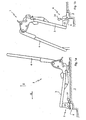
- Fig. 1 illustrated vehicle seat 1, of which only the metal structure is shown without cushions, consists of a vehicle floor 2 releasably anchored seat part 3, which in turn is pivotally connected to the backrest 4. From the position of use after Fig. 1a out, in which the backrest 4 substantially vertically and the seat part 3 are aligned almost horizontally, the backrest 4 can be folded onto the seat part 3 and the resulting package can be pivoted forward in a vertical stowed position ( Fig. 1 b) , Such an arrangement is known and is commonly referred to as "fold &tumble".
- the Vorschwenken via a in the front, detachable receptacle 5 integrated joint 6.
- the following terms "front” and “back” refer to the line of sight of the seat occupant, "front” usually the -X direction of the current coordinate system of Vehicle, so the direction of travel corresponds. In a transversely arranged to the direction of travel vehicle seat is naturally to use the Y-axis.
- the term “assembly” below the installation of the vehicle seat is understood in the use position of at least the seat part.
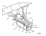
- the front seat 5 for the vehicle seat 1 is as shown Fig. 2 seen from a trough-like holder 7, which is formed from a sheet metal part and held open at its front end.
- a recessed in the lateral vertical surfaces 8 of the holder 7 bolt 9 extends at a distance from the horizontal surface 10 transversely and horizontally through the front portion of the holder. 7
- the bolt 9 is encompassed when mounted vehicle seat 1 by a seat part 3 arranged on the jaw 11, which is equipped with a pivot bolt 12.
- the pivot bolt 12 is biased by a leg spring 13 in the direction of its closed position. In this position, although the vehicle seat 1 may be pivoted forward about the bolt 9, it is still connected to the vehicle floor 2.
- a tab 14 which is accessible at vorklapptem seat part 3 (see Fig. 1 b) , the pivot bolt can be opened and the vehicle seat 1 removed.
- spring means 16 in the form of a U-shaped spring clip 17 are inserted, which extends below the bolt 9 to the front. How out Fig. 3 seen, collar the legs 18 of the spring clip 17 to the rear of the vertical surface 15 of the Holder 7 and find in a downwardly bent edge 19 of the holder 7, an abutment which holds the spring clip 17 in its approximately horizontal position.
- the parallel to the bolt 9 extending front base 20 of the spring clip 17 is in vorwenktem seat part 3 (Fig. Fig. 3b ) unloaded, is when folding the seat part in its position of use ( Fig. 3a ), however, detected by the front lower edge 21 of the catching mouth 11 and stretched upwards. In this case, the spring clip 17 comes into abutment with the pin 9 and thus compensates for tolerances in the vertical (Z) direction of the vehicle.
- the catching mouth 11 and the adjoining connecting parts 22 to the seat part 3 are also at least partially provided with a coating 23 made of a lubricious, thermoplastic material, in particular POM, which also includes the area of possible contact with the rear vertical surface 15 of the holder 7.
- this coating 22 is elastically compressed by contact with the vertical surface 15, whereby the catching jaw in the -X direction on the bolt 9 is tensioned.
- tolerances in the direction of the seat occupant are compensated.
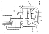
- projections 24, which surround the pin 9 arcuately and can be brought into contact with the extending within the holder 7 areas of the legs 18 of the spring clip 17 during pivoting of the seat part 3 in its position of use.
- the projections 24 widen in the mounting direction A wedge-shaped and are therefore suitable to spread the spring clip 17 during assembly.
- a balance of the game between recording 5 and jaw 11 is also in a horizontal transverse direction (Y-direction) of the vehicle.
- tolerances in all coordinates of the vehicle during assembly of the vehicle seat are compensated without further action, so that rattling or squeaking noise during operation of the vehicle can be prevented.
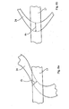
- the projections 24 In order to reduce the cycle times in the injection molding of the coating provided with the projections 24, it can be provided to make the projections 24 in a lateral view wave-like and overall thinner ( Fig. 5 ) to avoid cooling-critical material buildup.
- the surface pressure In the areas of the projections 24, which extend in the course of the sliding movement relative to the spring clip 17 obliquely, the surface pressure is reduced by the increased contact surface due to the inclination.
- the wall thickness d 1 of the projections 24 can be made particularly small there ( Fig. 6a ).
- the regions of the projections 24, however, which are aligned orthogonal to this when applied to the spring clip 17 can be provided with corresponding thickening (wall thickness d 2 ) ( Fig. 6b ).
Landscapes
- Engineering & Computer Science (AREA)
- Aviation & Aerospace Engineering (AREA)
- Transportation (AREA)
- Mechanical Engineering (AREA)
- Seats For Vehicles (AREA)
Description
- Die Erfindung betrifft einen Fahrzeugsitz, insbesondere eine Sitzbank für ein Kraftfahrzeug, der mittels mindestens eines eine Aufnahme umgreifenden Fangmauls lösbar am Fahrzeugboden verankerbar ist, mit Mitteln zur Kompensation von Toleranzen zwischen Fangmaul und Aufnahme, wobei die Aufnahme einen horizontalen, quer zur Sitzrichtung verlaufenden Bolzen umfasst, welcher in einer wannenartigen Halterung angeordnet ist, und wobei die Mittel insbesondere zur Kompensation von Toleranzen in vertikaler Richtung geeignet sind und Federmittel umfassen, welche bei der Montage des Fahrzeugsitzes vom Fangmaul gegen den Bolzen pressbar sind.
- Ein Fahrzeugsitz der eingangs genannten Art wird in der Gebrauchsmusterschrift
DE 200 06 691 U1 offenbart. Der Fahrzeugsitz ist mit schwenkbaren Drehfallen ausgestattet, welche zum Umgreifen von am Fahrzeugboden befestigten Bolzen vorgesehen sind. Eine Sicherheitseinrichtung weist einen auf die Drehfalle wirkenden Nocken auf, der von einem federbelasteten oder federartigen Steuerelement angesteuert wird, sobald dieses mit dem Bolzen in Kontakt gerät. Der Mechanismus ist dazu geeignet, einen selbstnachstellenden Toleranz- und Spielausgleich der Lage des Bolzens zu bewirken. In Y-Richtung des Fahrzeugs kann der Bolzen ferner über Gummielemente gedämpft werden. Eine ähnliche Vorrichtung ist aus der PatentschriftUS 6,629,710 B1 bekannt. - Diese Ausbildungen sind technisch anspruchsvoll und damit vergleichsweise kostenintensiv.
- In der Patentschrift
US 6,283,550 B1 wird eine hakenförmige Ausnehmung in einer Sitzhalterung beschrieben, die in dem zum Umgreifen eines Bolzens vorgesehenen Bereich zur Vermeidung von Geräuschen mit einer Kunststoffbeschichtung versehen ist. - Aus der Patentanmeldung
EP 1 160 121 A1 ist ein Drehfallenschloss zur seitlichen Verriegelung einer schwenkbaren Rückenlehne an der Fahrzeugkarosserie bekannt, bei welchem in der Ausnehmung der Drehfalle ein Dämpfungselement angeordnet ist. - Die Offenlegungsschrift
DE 199 16 422 A1 beschreibt ein Drehfallenschloss zur Befestigung eines Fahrzeugsitzes am Fahrzeugboden, das mit einer sich unter Vorspannung am Fahrzeugboden abstützenden Blattfeder ausgestattet ist. - Aus der Offenlegungsschrift
DE 103 10 382 A1 ist ein weiterer Fahrzeugsitz bekannt. Er weist eine Vorrichtung zur lösbaren Befestigung am Boden einer Fahrzeugkarosserie auf, welche ein in ein stabförmiges Gegenstück lösbar einsetzbares Fangmaul sowie eine gegenüber dem Fangmaul um eine Drehachse von einer Arretierstellung in eine Lösestellung schwenkbar angeordnete Verriegelungsklaue umfasst, mit welcher das Gegenstück umgreifbar ist. Die Verriegelungsklaue ist gegenüber dem Fangmaul entlang der Drehachse verschiebbar ausgebildet und nach der Verschiebung in die Lösestellung schwenkbar. - Besondere Mittel zur Kompensation von Toleranzen zwischen Fangmaul und Gegenstück werden dabei nicht offenbart.
- Der Erfindung liegt die Aufgabe zugrunde, einen gattungsgemäßen Fahrzeugsitz derart auszubilden, dass mit konstruktiv einfachen und kostengünstigen Mitteln beim Betrieb des Fahrzeugs eine Geräuschentwicklung im Bereich der Aufnahme verhindert und auch eine Kompensation von Toleranzen quer zur Sitzrichtung gewährleistet wird. Darüber hinaus soll die Montage des Fahrzeugsitzes auch von einer Person problemlos durchführbar sein.
- Die Aufgabe wird erfindungsgemäß dadurch gelöst, dass die Federmittel als an der hinteren Vertikalfläche der Halterung befestigter Federbügel ausgebildet sind, welcher sich U-förmig unterhalb des Bolzens nach vorne erstreckt und bei der Montage des Fahrzeugsitzes von der vorderen Unterkante des Fangmauls nach oben spannbar ist.
- Die Unteransprüche betreffen bevorzugte Ausführungsformen der Erfindung.
- Die Figuren stellen beispielhaft und schematisch verschiedene Ausführungen der Erfindung dar.
- Es zeigen:
- Fig. 1
- einen erfindungsgemäßen Fahrzeugsitz in Gebrauchsstellung (
Fig. 1a ) und Staustellung (Fig. 1b ), - Fig. 2
- eine perspektivische Ansicht der vorderen Aufnahme des Fahrzeugsitzes,
- Fig. 3
- eine seitliche Ansicht der Aufnahme in Gebrauchsstellung (
Fig. 3a ) und Staustellung (Fig. 3b ) des Fahrzeugsitzes, - Fig. 4
- die Aufnahme nach
Fig. 3a in frontaler Ansicht, - Fig. 5
- eine seitliche Ansicht der Aufnahme nach einer anderen Ausführung der Erfindung,
- Fig. 6
- vergrößerte Ausschnitte aus
Fig. 5 in verschiedenen Stadien des Montageprozesses, - Fig. 7
- das Einsetzen des entnommenen Fahrzeugsitzes in die Aufnahme.
- Der in
Fig. 1 abgebildete Fahrzeugsitz 1, von welchem nur die Metallstruktur ohne Polsterauflagen gezeigt wird, besteht aus einem am Fahrzeugboden 2 lösbar verankerten Sitzteil 3, das seinerseits gelenkig mit der Rückenlehne 4 verbunden ist. Aus der Gebrauchsstellung nachFig. 1a heraus, in welcher die Rückenlehne 4 im Wesentlichen senkrecht und das Sitzteil 3 nahezu waagerecht ausgerichtet sind, können die Rückenlehne 4 auf das Sitzteil 3 geklappt und das so entstandene Paket nach vorne in eine vertikale Staustellung geschwenkt werden (Fig. 1 b) . Eine derartige Anordnung ist bekannt und wird üblicherweise als "fold & tumble" bezeichnet. - Das Vorschwenken erfolgt über ein in die vordere, lösbare Aufnahme 5 integriertes Gelenk 6. Die nachfolgend genannten Begriffe "vorne" und "hinten" beziehen sich dabei auf die Blickrichtung des Sitzinsassen, wobei "vorne" üblicherweise der -X-Richtung des gängigen Koordinatensystems des Fahrzeugs, also der Fahrtrichtung, entspricht. Bei einem quer zur Fahrtrichtung angeordneten Fahrzeugsitz ist naturgemäß die Y-Achse heranzuziehen. Unter "Montage" wird nachfolgend der Einbau des Fahrzeugsitzes in die Gebrauchsstellung zumindest des Sitzteils verstanden.
- Die vordere Aufnahme 5 für den Fahrzeugsitz 1 besteht, wie aus
Fig. 2 ersichtlich, aus einer wannenartige Halterung 7, die aus einem Blechteil geformt und an ihrem vorderen Ende offen gehalten ist. Ein in die seitlichen Vertikalflächen 8 der Halterung 7 eingelassener Bolzen 9 erstreckt sich mit Abstand zur Horizontalfläche 10 quer und waagerecht durch den vorderen Bereich der Halterung 7. - Der Bolzen 9 wird bei montiertem Fahrzeugsitz 1 von einem am Sitzteil 3 angeordneten Fangmaul 11 umgriffen, das mit einem Schwenkriegel 12 ausgestattet ist. Der Schwenkriegel 12 wird mittels einer Schenkelfeder 13 in Richtung seiner Schließstellung vorgespannt. In dieser Stellung kann der Fahrzeugsitz 1 zwar um den Bolzen 9 herum nach vorne geschwenkt werden, ist jedoch weiterhin mit dem Fahrzeugboden 2 verbunden. Durch Ziehen an einer Lasche 14, die bei vorgeklapptem Sitzteil 3 zugänglich wird (siehe
Fig. 1 b) , können der Schwenkriegel geöffnet und der Fahrzeugsitz 1 entnommen werden. - In die hintere Vertikalfläche 15 der Halterung 7 sind Federmittel 16 in Form eines U-förmigen Federbügels 17 eingelassen, der sich unterhalb des Bolzens 9 nach vorne erstreckt. Wie aus
Fig. 3 ersichtlich, kragen die Schenkel 18 des Federbügels 17 nach hinten aus der Vertikalfläche 15 der Halterung 7 aus und finden in einer nach unten geneigten Abkantung 19 der Halterung 7 ein Widerlager, welches den Federbügel 17 in seiner etwa horizontalen Stellung hält. Die parallel zum Bolzen 9 verlaufende vordere Basis 20 des Federbügels 17 ist bei vorgeschwenktem Sitzteil 3 (Fig. 3b ) unbelastet, wird beim Klappen des Sitzteils in seine Gebrauchsstellung (Fig. 3a ) jedoch von der vorderen Unterkante 21 des Fangmauls 11 erfasst und nach oben gespannt. Dabei gerät der Federbügel 17 in Anlage an den Bolzen 9 und kompensiert somit Toleranzen in vertikaler (Z-) Richtung des Fahrzeugs. - Das Fangmaul 11 und die angrenzenden Verbindungsteile 22 zum Sitzteil 3 sind ferner zumindest partiell mit einer Beschichtung 23 aus einem gleitfähigem, thermoplastischen Kunststoff, insbesondere POM, versehen, welche auch den Bereich der möglichen Anlage an die hintere Vertikalfläche 15 der Halterung 7 umfasst. In Gebrauchsstellung des Sitzteils 3 (
Fig. 3a ) wird diese Beschichtung 22 durch Kontakt mit der Vertikalfläche 15 elastisch komprimiert, wodurch das Fangmaul in -X-Richtung auf den Bolzen 9 zu gespannt wird. Somit werden auch Toleranzen in Sichtrichtung des Sitzinsassen ausgeglichen. - An die Beschichtung 23 beidseitig einstückig angeformt sind Vorsprünge 24, welche den Bolzen 9 bogenförmig umgeben und beim Schwenken des Sitzteils 3 in seine Gebrauchsstellung in Kontakt mit den sich innerhalb der Halterung 7 erstreckenden Bereichen der Schenkel 18 des Federbügels 17 bringbar sind. Die Vorsprünge 24 erweitern sich in Montagerichtung A keilförmig und sind daher geeignet, den Federbügel 17 bei der Montage aufzuspreizen. Damit erfolgt ein Ausgleich des Spiels zwischen Aufnahme 5 und Fangmaul 11 auch in einer horizontalen Querrichtung (Y-Richtung) des Fahrzeugs.
- Durch das Zusammenwirken aller genannten Maßnahmen werden somit Toleranzen in allen Koordinaten des Fahrzeugs bei der Montage des Fahrzeugsitzes ohne weiteres Zutun kompensiert, so dass Klapper- oder Quietschgeräusche beim Betrieb des Fahrzeugs verhindert werden.
- Um die Taktzeiten beim Spritzgießen der mit den Vorsprüngen 24 ausgestatteten Beschichtung zu verringern, kann vorgesehen werden, die Vorsprünge 24 in seitlicher Ansicht wellenartig und insgesamt dünner auszuführen (
Fig. 5 ), um abkühlkritische Materialanhäufungen zu vermeiden. In den Bereichen der Vorsprünge 24, welche im Verlaufe der Gleitbewegung relativ zum Federbügel 17 schräg verlaufen, wird die Flächenpressung durch die infolge der Neigung vergrößerten Kontaktfläche verringert. Die Wanddicke d1 der Vorsprünge 24 kann dort besonders gering ausgebildet werden (Fig. 6a ). Die Bereiche der Vorsprünge 24 hingegen, die bei Anlage am Federbügel 17 orthogonal zu diesem ausgerichtet sind, können mit entsprechenden Verdickungen (Wanddicke d2) versehen werden (Fig. 6b ). - Beim Einsetzen des zuvor entnommenen Fahrzeugsitzes 1 in das Fahrzeug wird dieser, vorzugsweise bei vorgeklappter Rückenlehne, auf eine hinter der Aufnahme 5 befindliche karosserieseitige Horizontalfläche, beispielsweise den Kofferraumboden 25, aufgesetzt. Das Sitzteil 3 wird gegenüber dem Kofferraumboden 25 von einer außerhalb des Fahrzeugs stehenden und durch die Heckklappe greifenden Person in einer Schrägstellung gehalten (
Fig. 7a ). Das Gewicht des Fahrzeugsitzes 1 wird dabei im Wesentlichen über das Fangmaul 11 in den Kofferraumboden 25 abgeleitet. Der Fahrzeugsitz 1 kann nachfolgend nach vorne geschoben werden (-X-Richtung), bis das Fangmaul 11 unter Schwerkraftwirkung in die wannenartige Halterung 7 einfällt (Fig. 7b ). Beim Kontakt mit dem Bolzen 9 wird der Schwenkriegel 12 gegen die Kraft der Schenkelfeder 13 zunächst geöffnet und umschließt den Bolzen beim weiteren Vorschieben. Nachfolgend kann das Sitzteil 3 um den Bolzen 9 herum nach unten in seine Gebrauchsstellung geschwenkt werden (Pfeil A), wobei die zuvor beschriebene Toleranzkompensation erfolgt. Nach dem Hochklappen der Rückenlehne 4 ist die Montage des Fahrzeugsitzes 1 vollständig abgeschlossen. -
- 1
- Fahrzeugsitz
- 2
- Fahrzeugboden
- 3
- Sitzteil
- 4
- Rückenlehne
- 5
- Aufnahme
- 6
- Gelenk
- 7
- Halterung
- 8
- Vertikalfläche (seitlich) der Halterung
- 9
- Bolzen
- 10
- Horizontalfläche der Halterung
- 11
- Fangmaul
- 12
- Schwenkriegel
- 13
- Schenkelfeder
- 14
- Lasche
- 15
- Vertikalfläche (hinten) der Halterung
- 16
- Federmittel
- 17
- Federbügel
- 18
- Schenkel (des Federbügels)
- 19
- Abkantung (der Halterung)
- 20
- Basis (des Federbügels)
- 21
- vordere Unterkante (des Fangmauls)
- 22
- Verbindungsteil
- 23
- Beschichtung
- 24
- Vorsprünge
- 25
- Kofferraumboden
Claims (10)
- Fahrzeugsitz (1), insbesondere Sitzbank für ein Kraftfahrzeug, der mittels mindestens eines eine Aufnahme (5) umgreifenden Fangmauls (11) lösbar am Fahrzeugboden (2) verankerbar ist, mit Mitteln zur Kompensation von Toleranzen zwischen Fangmaul (11) und Aufnahme (5), wobei die Aufnahme (5) einen horizontalen, quer zur Sitzrichtung verlaufendenBolzen (9) umfasst, welcher in einer wannenartigen Halterung (7) angeordnet ist, und die Mittel insbesondere zur Kompensation von Toleranzen in vertikaler Richtung geeignet sind und Federmittel (16) umfassen, welche bei der Montage des Fahrzeugsitzes (1) vom Fangmaul (11) gegen den Bolzen (9) pressbar sind, dadurch gekennzeichnet, dass die Federmittel (16) als an der hinteren Vertikalfläche (15) der Halterung (7) befestigter Federbügel (17) ausgebildet sind, welcher sich U-förmig unterhalb des Bolzens (9) nach vorne erstreckt und bei der Montage des Fahrzeugsitzes (1) von der vorderen Unterkante (21) des Fangmauls (11) nach oben spannbar ist.
- Fahrzeugsitz nach einem der Ansprüche 1, dadurch gekennzeichnet, dass die Mittel insbesondere zur Kompensation von horizontalen Toleranzen in Sitzrichtung geeignet sind und das Fangmaul (11) und/oder die Aufnahme (5) zumindest im Bereich der Anlage an der Auflage (5) und/oder dem Fangmaul (11) mit einer Beschichtung (23) versehen sind, welche bei der Montage des Fahrzeugsitzes (1) elastisch verformbar ist.
- Fahrzeugsitz nach Anspruch 2, dadurch gekennzeichnet, dass die elastische Verformung in der Anlage des hinteren Bereichs des Fangmauls (11) an der wannenartigen Halterung (7) erfolgt, wodurch das Fangmaul (11) bei der Montage des Fahrzeugsitzes (1) in Richtung des Bolzens (9) spannbar ist.
- Fahrzeugsitz nach einem der Ansprüche 1 bis 3, dadurch gekennzeichnet, dass die Mittel insbesondere zur Kompensation von horizontalen Toleranzen quer zur Sitzrichtung geeignet sind und seitlich an das Fangmaul (11) angeformte Vorsprünge (24) umfassen, welche bei der Montage des Fahrzeugsitzes (1) an vertikale Gegenflächen der Aufnahme (5) pressbar sind.
- Fahrzeugsitz nach Anspruch 4, dadurch gekennzeichnet, dass die Vorsprünge (24) bei der Montage des Fahrzeugsitzes (1) an den Federbügel (17) pressbar sind.
- Fahrzeugsitz nach Anspruch 4 oder 5, dadurch gekennzeichnet, dass die Vorsprünge (24), in seitlicher Ansicht, das Fangmaul (11) bogenförmig umgebend ausgebildet sind und sich, in frontaler Ansicht, in Montagerichtung keilförmig erweitern.
- Fahrzeugsitz nach Anspruch 6, dadurch gekennzeichnet, dass die Vorsprünge (24) innerhalb der bogenförmigen Kontur wellenartig ausgebildet sind, wobei die bei der Montage am Federbügel (17) orthogonal anliegenden Bereiche der wellenartigen Ausbildung vorzugsweise verdickt ausgeführt sind.
- Fahrzeugsitz nach einem der Ansprüche 4 bis 7, dadurch gekennzeichnet, dass die Vorsprünge (24) einstückig an die Beschichtung (23) angeformt sind.
- Fahrzeugsitz nach einem der vorhergehenden Ansprüche, dadurch gekennzeichnet, dass das Fangmaul (11) bei der Montage des Fahrzeugsitzes (1) von hinten in Richtung der Aufnahme (5) über eine karosserieseitige Horizontalfläche schiebbar ist und bei Erreichen der Aufnahme (5) mit dieser ohne weiteres Zutun in Eingriff bringbar ist.
- Fahrzeugsitz nach Anspruch 9, dadurch gekennzeichnet, dass das Fangmaul (11) beim Erreichen der Aufnahme (5) unter Schwerkraftwirkung und Umgreifen des Bolzens (9) nach unten in die wannenartige Halterung (7) einbringbar ist.
Applications Claiming Priority (2)
| Application Number | Priority Date | Filing Date | Title |
|---|---|---|---|
| DE102005024816A DE102005024816B4 (de) | 2005-05-27 | 2005-05-27 | Fahrzeugsitz, insbesondere Sitzbank für ein Kraftfahrzeug |
| PCT/EP2006/003894 WO2006128531A1 (de) | 2005-05-27 | 2006-04-27 | Fahrzeugsitz, insbesondere sitzbank für ein kraftfahrzeug |
Publications (2)
| Publication Number | Publication Date |
|---|---|
| EP1888366A1 EP1888366A1 (de) | 2008-02-20 |
| EP1888366B1 true EP1888366B1 (de) | 2011-02-02 |
Family
ID=36593071
Family Applications (1)
| Application Number | Title | Priority Date | Filing Date |
|---|---|---|---|
| EP06724594A Expired - Lifetime EP1888366B1 (de) | 2005-05-27 | 2006-04-27 | Fahrzeugsitz, insbesondere sitzbank für ein kraftfahrzeug |
Country Status (4)
| Country | Link |
|---|---|
| EP (1) | EP1888366B1 (de) |
| AT (1) | ATE497454T1 (de) |
| DE (2) | DE102005024816B4 (de) |
| WO (1) | WO2006128531A1 (de) |
Families Citing this family (2)
| Publication number | Priority date | Publication date | Assignee | Title |
|---|---|---|---|---|
| DE102009056775B4 (de) * | 2009-12-03 | 2023-12-21 | Volkswagen Ag | Toleranzausgleichselement für einen entnehmbaren Fahrzeugsitz oder eine entnehmbare Sitzbank |
| DE102021122645B4 (de) * | 2021-09-01 | 2023-12-21 | Bayerische Motoren Werke Aktiengesellschaft | Vorrichtung zum Verankern eines Sitzes in einem Kraftfahrzeug |
Family Cites Families (8)
| Publication number | Priority date | Publication date | Assignee | Title |
|---|---|---|---|---|
| FR2780351B1 (fr) | 1998-06-26 | 2000-09-08 | Faure Bertrand Equipements Sa | Siege de vehicule a ancrage avant automatique, et vehicule comportant un tel siege |
| DE19916422B4 (de) | 1999-04-07 | 2006-07-27 | Brose Fahrzeugteile Gmbh & Co. Kommanditgesellschaft, Coburg | Vorrichtung zur lösbaren Befestigung eines Fahrzeugsitzes am Fahrzeugboden |
| DE19930945C1 (de) * | 1999-07-05 | 2001-03-22 | Keiper Gmbh & Co | Befestigungsvorrichtung für den am Sitzteil oder Sitzrahmen festgelegten Beschlagteil eines Beschlages |
| DE29912439U1 (de) | 1999-07-16 | 2000-11-30 | Johnson Controls GmbH, 51399 Burscheid | Verriegelungsvorrichtung und Verankerungssystem |
| DE20006691U1 (de) | 2000-04-11 | 2001-08-23 | Johnson Controls GmbH, 51399 Burscheid | Verbindungssystem |
| IT1320387B1 (it) | 2000-06-02 | 2003-11-26 | Atoma Roltra Spa | Dispositivo di vincolo di uno schienale di un sedile ad una scocca diun autoveicolo. |
| KR100461257B1 (ko) * | 2002-04-18 | 2004-12-10 | 기아자동차주식회사 | 차량의 탈착식 시트 |
| DE10310382B4 (de) | 2003-03-07 | 2016-09-29 | Johnson Controls Gmbh | Lösbare Befestigungseinrichtung, insbesondere für Fahrzeugsitze |
-
2005
- 2005-05-27 DE DE102005024816A patent/DE102005024816B4/de not_active Expired - Fee Related
-
2006
- 2006-04-27 WO PCT/EP2006/003894 patent/WO2006128531A1/de not_active Ceased
- 2006-04-27 AT AT06724594T patent/ATE497454T1/de active
- 2006-04-27 EP EP06724594A patent/EP1888366B1/de not_active Expired - Lifetime
- 2006-04-27 DE DE502006008848T patent/DE502006008848D1/de not_active Expired - Lifetime
Also Published As
| Publication number | Publication date |
|---|---|
| DE102005024816A1 (de) | 2006-11-30 |
| DE102005024816B4 (de) | 2007-04-19 |
| EP1888366A1 (de) | 2008-02-20 |
| DE502006008848D1 (de) | 2011-03-17 |
| WO2006128531A1 (de) | 2006-12-07 |
| ATE497454T1 (de) | 2011-02-15 |
Similar Documents
| Publication | Publication Date | Title |
|---|---|---|
| EP2310227B1 (de) | Verriegelungsvorrichtung für einen fahrzeugsitz | |
| AT502486B1 (de) | Anordnung mit einem scharnier, insbesondere möbelscharnier | |
| EP2310226A1 (de) | Verriegelungsvorrichtung für einen fahrzeugsitz | |
| WO2010003586A1 (de) | Verriegelungsvorrichtung für einen fahrzeugsitz | |
| DE102012015854A1 (de) | Verriegelungseinheit für einen Fahrzeugsitz | |
| DE102012011515A1 (de) | Verriegelungseinheit für einen Fahrzeugsitz | |
| DE19531018A1 (de) | Gelenkbeschlag für Fahrzeugsitze, insbesondere Kraftfahrzeugsitze | |
| DE19928862A1 (de) | Befestigungsvorrichtung für einen Kindersitz | |
| DE102007058331B4 (de) | Fahrzeugsitz | |
| EP1888366B1 (de) | Fahrzeugsitz, insbesondere sitzbank für ein kraftfahrzeug | |
| WO2017174282A1 (de) | Haltegriffanordnung, fahrzeug | |
| DE10247069B4 (de) | Verstelleinrichtung für die Rückenlehne von Sitzen | |
| DE69302983T2 (de) | Abnehmbarer und durch Handbetätigung schwenkbarer Befestigungsclip und diesen enthaltende Verbindungsvorrichtung | |
| DE102005060709B4 (de) | Bremse für das Ringscharnier an einer Kraftfahrzeugtür | |
| DE19849070C1 (de) | Unterlenkerbaueinheit für eine Geräteanbaueinrichtung | |
| DE19961618C1 (de) | Rückenlehne für einen Fahrzeugsitz | |
| DE19526317C2 (de) | Vorrichtung für die Längsverstellung eines Kraftfahrzeugsitzes | |
| DE102005039305B4 (de) | Rückenlehne für ein Fahrzeug | |
| DE102005003818B4 (de) | Fahrzeugsitz mit klappbarer Rückenlehne | |
| DE102005025002B4 (de) | Beschlag für einen Fahrzeugsitz | |
| DE102005028771B4 (de) | Kraftfahrzeugsitz | |
| DE10154395B4 (de) | Verriegelungsvorrichtung mit einer Verriegelungsklinke | |
| EP0858922A1 (de) | Vorrichtung zur Aufnahme des Tankstutzens bei Kraftfahrzeugen | |
| DE102023117530A1 (de) | Sonnenblendenbaugruppe für ein fahrzeug | |
| DE10255573B4 (de) | Türaußengriffanordnung für ein Kraftfahrzeug |
Legal Events
| Date | Code | Title | Description |
|---|---|---|---|
| PUAI | Public reference made under article 153(3) epc to a published international application that has entered the european phase |
Free format text: ORIGINAL CODE: 0009012 |
|
| 17P | Request for examination filed |
Effective date: 20071227 |
|
| AK | Designated contracting states |
Kind code of ref document: A1 Designated state(s): AT BE BG CH CY CZ DE DK EE ES FI FR GB GR HU IE IS IT LI LT LU LV MC NL PL PT RO SE SI SK TR |
|
| DAX | Request for extension of the european patent (deleted) | ||
| 17Q | First examination report despatched |
Effective date: 20100309 |
|
| GRAP | Despatch of communication of intention to grant a patent |
Free format text: ORIGINAL CODE: EPIDOSNIGR1 |
|
| GRAS | Grant fee paid |
Free format text: ORIGINAL CODE: EPIDOSNIGR3 |
|
| GRAA | (expected) grant |
Free format text: ORIGINAL CODE: 0009210 |
|
| AK | Designated contracting states |
Kind code of ref document: B1 Designated state(s): AT BE BG CH CY CZ DE DK EE ES FI FR GB GR HU IE IS IT LI LT LU LV MC NL PL PT RO SE SI SK TR |
|
| REG | Reference to a national code |
Ref country code: GB Ref legal event code: FG4D Free format text: NOT ENGLISH |
|
| REG | Reference to a national code |
Ref country code: CH Ref legal event code: EP |
|
| REG | Reference to a national code |
Ref country code: IE Ref legal event code: FG4D Free format text: LANGUAGE OF EP DOCUMENT: GERMAN |
|
| REF | Corresponds to: |
Ref document number: 502006008848 Country of ref document: DE Date of ref document: 20110317 Kind code of ref document: P |
|
| REG | Reference to a national code |
Ref country code: DE Ref legal event code: R096 Ref document number: 502006008848 Country of ref document: DE Effective date: 20110317 |
|
| REG | Reference to a national code |
Ref country code: NL Ref legal event code: VDEP Effective date: 20110202 |
|
| LTIE | Lt: invalidation of european patent or patent extension |
Effective date: 20110202 |
|
| PG25 | Lapsed in a contracting state [announced via postgrant information from national office to epo] |
Ref country code: LT Free format text: LAPSE BECAUSE OF FAILURE TO SUBMIT A TRANSLATION OF THE DESCRIPTION OR TO PAY THE FEE WITHIN THE PRESCRIBED TIME-LIMIT Effective date: 20110202 Ref country code: ES Free format text: LAPSE BECAUSE OF FAILURE TO SUBMIT A TRANSLATION OF THE DESCRIPTION OR TO PAY THE FEE WITHIN THE PRESCRIBED TIME-LIMIT Effective date: 20110513 Ref country code: GR Free format text: LAPSE BECAUSE OF FAILURE TO SUBMIT A TRANSLATION OF THE DESCRIPTION OR TO PAY THE FEE WITHIN THE PRESCRIBED TIME-LIMIT Effective date: 20110503 Ref country code: PT Free format text: LAPSE BECAUSE OF FAILURE TO SUBMIT A TRANSLATION OF THE DESCRIPTION OR TO PAY THE FEE WITHIN THE PRESCRIBED TIME-LIMIT Effective date: 20110602 Ref country code: SE Free format text: LAPSE BECAUSE OF FAILURE TO SUBMIT A TRANSLATION OF THE DESCRIPTION OR TO PAY THE FEE WITHIN THE PRESCRIBED TIME-LIMIT Effective date: 20110202 Ref country code: LV Free format text: LAPSE BECAUSE OF FAILURE TO SUBMIT A TRANSLATION OF THE DESCRIPTION OR TO PAY THE FEE WITHIN THE PRESCRIBED TIME-LIMIT Effective date: 20110202 |
|
| PG25 | Lapsed in a contracting state [announced via postgrant information from national office to epo] |
Ref country code: BG Free format text: LAPSE BECAUSE OF FAILURE TO SUBMIT A TRANSLATION OF THE DESCRIPTION OR TO PAY THE FEE WITHIN THE PRESCRIBED TIME-LIMIT Effective date: 20110502 Ref country code: NL Free format text: LAPSE BECAUSE OF FAILURE TO SUBMIT A TRANSLATION OF THE DESCRIPTION OR TO PAY THE FEE WITHIN THE PRESCRIBED TIME-LIMIT Effective date: 20110202 Ref country code: PL Free format text: LAPSE BECAUSE OF FAILURE TO SUBMIT A TRANSLATION OF THE DESCRIPTION OR TO PAY THE FEE WITHIN THE PRESCRIBED TIME-LIMIT Effective date: 20110202 Ref country code: SI Free format text: LAPSE BECAUSE OF FAILURE TO SUBMIT A TRANSLATION OF THE DESCRIPTION OR TO PAY THE FEE WITHIN THE PRESCRIBED TIME-LIMIT Effective date: 20110202 Ref country code: FI Free format text: LAPSE BECAUSE OF FAILURE TO SUBMIT A TRANSLATION OF THE DESCRIPTION OR TO PAY THE FEE WITHIN THE PRESCRIBED TIME-LIMIT Effective date: 20110202 Ref country code: CY Free format text: LAPSE BECAUSE OF FAILURE TO SUBMIT A TRANSLATION OF THE DESCRIPTION OR TO PAY THE FEE WITHIN THE PRESCRIBED TIME-LIMIT Effective date: 20110202 |
|
| REG | Reference to a national code |
Ref country code: IE Ref legal event code: FD4D |
|
| BERE | Be: lapsed |
Owner name: JOHNSON CONTROLS G.M.B.H. Effective date: 20110430 |
|
| PG25 | Lapsed in a contracting state [announced via postgrant information from national office to epo] |
Ref country code: EE Free format text: LAPSE BECAUSE OF FAILURE TO SUBMIT A TRANSLATION OF THE DESCRIPTION OR TO PAY THE FEE WITHIN THE PRESCRIBED TIME-LIMIT Effective date: 20110202 Ref country code: IE Free format text: LAPSE BECAUSE OF FAILURE TO SUBMIT A TRANSLATION OF THE DESCRIPTION OR TO PAY THE FEE WITHIN THE PRESCRIBED TIME-LIMIT Effective date: 20110202 Ref country code: DK Free format text: LAPSE BECAUSE OF FAILURE TO SUBMIT A TRANSLATION OF THE DESCRIPTION OR TO PAY THE FEE WITHIN THE PRESCRIBED TIME-LIMIT Effective date: 20110202 |
|
| PG25 | Lapsed in a contracting state [announced via postgrant information from national office to epo] |
Ref country code: SK Free format text: LAPSE BECAUSE OF FAILURE TO SUBMIT A TRANSLATION OF THE DESCRIPTION OR TO PAY THE FEE WITHIN THE PRESCRIBED TIME-LIMIT Effective date: 20110202 Ref country code: CZ Free format text: LAPSE BECAUSE OF FAILURE TO SUBMIT A TRANSLATION OF THE DESCRIPTION OR TO PAY THE FEE WITHIN THE PRESCRIBED TIME-LIMIT Effective date: 20110202 Ref country code: MC Free format text: LAPSE BECAUSE OF NON-PAYMENT OF DUE FEES Effective date: 20110430 Ref country code: RO Free format text: LAPSE BECAUSE OF FAILURE TO SUBMIT A TRANSLATION OF THE DESCRIPTION OR TO PAY THE FEE WITHIN THE PRESCRIBED TIME-LIMIT Effective date: 20110202 |
|
| REG | Reference to a national code |
Ref country code: CH Ref legal event code: PL |
|
| PLBE | No opposition filed within time limit |
Free format text: ORIGINAL CODE: 0009261 |
|
| STAA | Information on the status of an ep patent application or granted ep patent |
Free format text: STATUS: NO OPPOSITION FILED WITHIN TIME LIMIT |
|
| 26N | No opposition filed |
Effective date: 20111103 |
|
| GBPC | Gb: european patent ceased through non-payment of renewal fee |
Effective date: 20110502 |
|
| PG25 | Lapsed in a contracting state [announced via postgrant information from national office to epo] |
Ref country code: BE Free format text: LAPSE BECAUSE OF NON-PAYMENT OF DUE FEES Effective date: 20110430 Ref country code: LI Free format text: LAPSE BECAUSE OF NON-PAYMENT OF DUE FEES Effective date: 20110430 Ref country code: CH Free format text: LAPSE BECAUSE OF NON-PAYMENT OF DUE FEES Effective date: 20110430 |
|
| REG | Reference to a national code |
Ref country code: DE Ref legal event code: R097 Ref document number: 502006008848 Country of ref document: DE Effective date: 20111103 |
|
| PG25 | Lapsed in a contracting state [announced via postgrant information from national office to epo] |
Ref country code: IT Free format text: LAPSE BECAUSE OF FAILURE TO SUBMIT A TRANSLATION OF THE DESCRIPTION OR TO PAY THE FEE WITHIN THE PRESCRIBED TIME-LIMIT Effective date: 20110202 |
|
| PG25 | Lapsed in a contracting state [announced via postgrant information from national office to epo] |
Ref country code: GB Free format text: LAPSE BECAUSE OF NON-PAYMENT OF DUE FEES Effective date: 20110502 |
|
| REG | Reference to a national code |
Ref country code: AT Ref legal event code: MM01 Ref document number: 497454 Country of ref document: AT Kind code of ref document: T Effective date: 20110427 |
|
| PG25 | Lapsed in a contracting state [announced via postgrant information from national office to epo] |
Ref country code: AT Free format text: LAPSE BECAUSE OF NON-PAYMENT OF DUE FEES Effective date: 20110427 |
|
| PG25 | Lapsed in a contracting state [announced via postgrant information from national office to epo] |
Ref country code: LU Free format text: LAPSE BECAUSE OF NON-PAYMENT OF DUE FEES Effective date: 20110427 |
|
| PG25 | Lapsed in a contracting state [announced via postgrant information from national office to epo] |
Ref country code: IS Free format text: LAPSE BECAUSE OF FAILURE TO SUBMIT A TRANSLATION OF THE DESCRIPTION OR TO PAY THE FEE WITHIN THE PRESCRIBED TIME-LIMIT Effective date: 20110202 |
|
| PG25 | Lapsed in a contracting state [announced via postgrant information from national office to epo] |
Ref country code: TR Free format text: LAPSE BECAUSE OF FAILURE TO SUBMIT A TRANSLATION OF THE DESCRIPTION OR TO PAY THE FEE WITHIN THE PRESCRIBED TIME-LIMIT Effective date: 20110202 |
|
| PG25 | Lapsed in a contracting state [announced via postgrant information from national office to epo] |
Ref country code: HU Free format text: LAPSE BECAUSE OF FAILURE TO SUBMIT A TRANSLATION OF THE DESCRIPTION OR TO PAY THE FEE WITHIN THE PRESCRIBED TIME-LIMIT Effective date: 20110202 |
|
| REG | Reference to a national code |
Ref country code: FR Ref legal event code: PLFP Year of fee payment: 11 |
|
| REG | Reference to a national code |
Ref country code: FR Ref legal event code: PLFP Year of fee payment: 12 |
|
| REG | Reference to a national code |
Ref country code: DE Ref legal event code: R081 Ref document number: 502006008848 Country of ref document: DE Owner name: ADIENT LUXEMBOURG HOLDING S.A.R.L., LU Free format text: FORMER OWNER: JOHNSON CONTROLS GMBH, 51399 BURSCHEID, DE Ref country code: DE Ref legal event code: R081 Ref document number: 502006008848 Country of ref document: DE Owner name: ADIENT LUXEMBOURG HOLDING S.A R.L., LU Free format text: FORMER OWNER: JOHNSON CONTROLS GMBH, 51399 BURSCHEID, DE |
|
| PGFP | Annual fee paid to national office [announced via postgrant information from national office to epo] |
Ref country code: FR Payment date: 20170419 Year of fee payment: 12 Ref country code: DE Payment date: 20170430 Year of fee payment: 12 |
|
| REG | Reference to a national code |
Ref country code: DE Ref legal event code: R081 Ref document number: 502006008848 Country of ref document: DE Owner name: ADIENT LUXEMBOURG HOLDING S.A R.L., LU Free format text: FORMER OWNER: ADIENT LUXEMBOURG HOLDING S.A.R.L., LUXEMBOURG, LU |
|
| REG | Reference to a national code |
Ref country code: DE Ref legal event code: R119 Ref document number: 502006008848 Country of ref document: DE |
|
| PG25 | Lapsed in a contracting state [announced via postgrant information from national office to epo] |
Ref country code: DE Free format text: LAPSE BECAUSE OF NON-PAYMENT OF DUE FEES Effective date: 20181101 |
|
| PG25 | Lapsed in a contracting state [announced via postgrant information from national office to epo] |
Ref country code: FR Free format text: LAPSE BECAUSE OF NON-PAYMENT OF DUE FEES Effective date: 20180430 |