EP1888403B1 - Rotornabenverkleidungssystem für ein gegenläufiges koaxiales rotorsystem - Google Patents
Rotornabenverkleidungssystem für ein gegenläufiges koaxiales rotorsystem Download PDFInfo
- Publication number
- EP1888403B1 EP1888403B1 EP06769926.4A EP06769926A EP1888403B1 EP 1888403 B1 EP1888403 B1 EP 1888403B1 EP 06769926 A EP06769926 A EP 06769926A EP 1888403 B1 EP1888403 B1 EP 1888403B1
- Authority
- EP
- European Patent Office
- Prior art keywords
- fairing
- rotor
- hub fairing
- shaft
- rotor hub
- Prior art date
- Legal status (The legal status is an assumption and is not a legal conclusion. Google has not performed a legal analysis and makes no representation as to the accuracy of the status listed.)
- Ceased
Links
Images





Classifications
-
- B—PERFORMING OPERATIONS; TRANSPORTING
- B64—AIRCRAFT; AVIATION; COSMONAUTICS
- B64C—AEROPLANES; HELICOPTERS
- B64C27/00—Rotorcraft; Rotors peculiar thereto
- B64C27/04—Helicopters
- B64C27/12—Rotor drives
-
- B—PERFORMING OPERATIONS; TRANSPORTING
- B64—AIRCRAFT; AVIATION; COSMONAUTICS
- B64C—AEROPLANES; HELICOPTERS
- B64C1/00—Fuselages; Constructional features common to fuselages, wings, stabilising surfaces or the like
-
- B—PERFORMING OPERATIONS; TRANSPORTING
- B64—AIRCRAFT; AVIATION; COSMONAUTICS
- B64C—AEROPLANES; HELICOPTERS
- B64C27/00—Rotorcraft; Rotors peculiar thereto
- B64C27/04—Helicopters
- B64C27/08—Helicopters with two or more rotors
- B64C27/10—Helicopters with two or more rotors arranged coaxially
-
- B—PERFORMING OPERATIONS; TRANSPORTING
- B64—AIRCRAFT; AVIATION; COSMONAUTICS
- B64C—AEROPLANES; HELICOPTERS
- B64C27/00—Rotorcraft; Rotors peculiar thereto
- B64C27/04—Helicopters
- B64C27/12—Rotor drives
- B64C27/14—Direct drive between power plant and rotor hub
-
- B—PERFORMING OPERATIONS; TRANSPORTING
- B64—AIRCRAFT; AVIATION; COSMONAUTICS
- B64C—AEROPLANES; HELICOPTERS
- B64C7/00—Structures or fairings not otherwise provided for
-
- B—PERFORMING OPERATIONS; TRANSPORTING
- B64—AIRCRAFT; AVIATION; COSMONAUTICS
- B64C—AEROPLANES; HELICOPTERS
- B64C27/00—Rotorcraft; Rotors peculiar thereto
- B64C27/04—Helicopters
-
- B—PERFORMING OPERATIONS; TRANSPORTING
- B64—AIRCRAFT; AVIATION; COSMONAUTICS
- B64C—AEROPLANES; HELICOPTERS
- B64C27/00—Rotorcraft; Rotors peculiar thereto
- B64C27/20—Rotorcraft characterised by having shrouded rotors, e.g. flying platforms
Definitions
- the present invention is directed to a rotor hub fairing system, and more particularly, to an integrated rotor hub fairing which is sized and configured to reduce overall drag for a high-speed rotary-wing aircraft a counter-rotating, coaxial rotor system, according to be characteristic of the preamble of independent claim 1 and to a coaxial rotor system comprising such a rotor hub fairing system.
- the aerodynamic drag associated with a rotor hub on a rotary wing aircraft is a significant portion of the overall aircraft drag, typically 25% to 30% for conventional single-rotor helicopters.
- the rotor system drag increases significantly for a rotary wing aircraft having a counter-rotating, coaxial rotor system primarily due to the extra rotor hub and the interconnecting shaft between the upper and lower rotor systems.
- the increased drag resulting from the counter-rotating, coaxial rotor system may result in a relatively significant power penalty.
- the aerodynamic drag of the dual counter-rotating, coaxial rotor system is generated by three main components - the upper hub, the lower hub, and the interconnecting rotor shaft assembly.
- the drag contribution may be approximately 40% for each of the hubs, and 20% for the interconnecting shaft assembly.
- Closest prior art US 2 328 786 discloses an aircraft in which the conventional wings are omitted and a pair of rotating wing systems is configured to provide power for lifting the aircraft from the ground as well as propelling the aircraft through the air.
- the aircraft has a pair of oppositely rotating wing structures which rotate upon a common axis substantially parallel with the axis of the fuselage of the aircraft, wherein the pair of rotating wing structures retains this parallel relation whether lifting the aircraft from the ground or propelling the same through the air. That is to say, the axis of the fuselage in general is always directed into an actual direction of flight.
- the fuselage as well as the part of the fuselage arranged between the pair of rotating wing systems is shaped rotational symmetric with respect to the axis of the fuselage, drag generated by the fuselage is minimized by suitable shape of the lateral outer outline of the fuselage.
- a rotor hub fairing system for a dual, counter-rotating, coaxial rotor system generally includes an upper hub fairing, a lower hub fairing and a shaft fairing located therebetween.
- the rotor hub fairing system is sized and configured to reduce the overall drag on the rotor system.
- the rotor hub fairing system is an integrated system that is refined through analysis and/or testing to reduce overall drag.
- the rotor hub fairing is viewed as a system for drag reduction, rather than drag reduction by the individual components.
- the rotor hub fairing system reduces drag by minimizing excessive separation in the surface junction areas. Furthermore, by introducing an integrated design, drag is reduced by accounting for the interference effects and optimal surface distributions for each rotor system configuration. The use of fillets at the intersecting surfaces further reduces the overall drag.
- the shaft fairing preferably includes a minimal thickness at the shaft fairing's midsection.
- the outer shaft fairing sections on each side of the shaft fairing midsection and adjacent the upper and lower hub fairings define a thickness greater than the shaft fairing's midsection. Minimizing the thickness at the midsection reduces drag while increasing the thickness at the outer shaft fairing sections reduces the flow separation on the hub fairing surfaces.
- the rotor hub fairing system may include a horizontal wing-like splitter airfoil which extends from the shaft fairing, preferably at the midsection.
- the splitter airfoil includes an airfoil profile which reduces drag and sensitivity to angle of attack variations.
- the airfoil shape of the splitter airfoil may provide a fixed or adjustable angle of attack to specifically tailor the rotor hub wake in a direction that reduces airframe and tail vibration.
- the rotor hub fairing system may include a plurality of turning vanes which facilitate flow around the aft end of the upper and lower hub fairings to reduce flow separation and drag.
- the rotor hub fairing system may include a plurality of turning vanes located adjacent the lower hub, a plurality of turning vanes located adjacent the upper hub or any combination thereof.
- the upper turning vane may be located adjacent the upper hub fairing and includes a camber which preferably follows the contour of the upper hub fairing while the lower turning vane may be located adjacent the lower hub fairing and preferably includes a camber which follows the contour of the lower hub fairing.
- the present invention therefore provides a drag-reducing rotor hub fairing system for a rotary wing aircraft having a counter-rotating, coaxial rotor system.
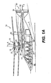
- Figures 1A-1B is a general schematic view of an exemplary rotary wing aircraft embodiment for use with present invention
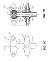
- Figure 1C is a side view of an integrated rotor hub fairing system designed according to the present invention.
- Figure 1D is a sectional side view of the integrated rotor hub fairing system taken along line D-D in Figure 1C ;
- Figure 1E is a partial phantom side view of an integrated rotor hub fairing system designed according to the present invention
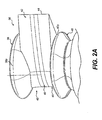
- Figure 2A is an oblique aft perspective view of an integrated rotor hub fairing system
- Figure 2B is a rear perspective view of the integrated rotor hub fairing system of Figure 2A ;
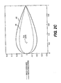
- Figure 2C is a schematic view of the airfoil shapes utilized with the shaft fairing of the integrated rotor hub fairing system of Figure 2A ;
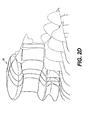
- Figure 2D is a computed total pressure contour produced by the rotor hub fairing system of Figure 2A ;
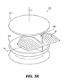
- Figure 3A is an oblique top perspective view of another integrated rotor hub fairing system with a splitter airfoil;
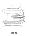
- Figure 3B is a side view of the integrated rotor hub fairing system of Figure 3A ;
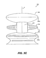
- Figure 3C is a front view of the integrated rotor hub fairing system of Figure 3A ;
- Figure 3D is a rear view of the integrated rotor hub fairing system of Figure 3A ;
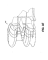
- Figure 3E is a computed total pressure contour produced by the rotor hub fairing system of Figure 3A ;
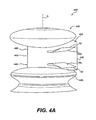
- Figure 4A is an oblique aft perspective view of another integrated rotor hub fairing system with a multitude of turning vanes;
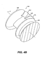
- Figure 4B is an oblique bottom perspective view of the integrated rotor hub fairing system of Figure 4A ;
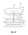
- Figure 4C is a rear perspective view of the integrated rotor hub fairing system of Figure 4A ;
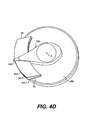
- Figure 4D is a top view of the integrated rotor hub fairing system of Figure 4A with the upper hub fairing removed;
- Figure 4E is a computed total pressure contour produce by the rotor hub failing system of Figure 4A .
- FIGS 1A and 1B illustrate an exemplary vertical takeoff and landing (VTOL) high speed rotary-wing aircraft 10 having a dual, counter-rotating, coaxial rotor system 12.
- the aircraft 10 includes an airframe 14 which supports the dual, counter rotating, coaxial rotor system 12 as well as a translational thrust system 30 which provides translational thrust generally parallel to an aircraft longitudinal axis L.
- VTOL vertical takeoff and landing
- the dual, counter-rotating, coaxial rotor system 12 includes an upper rotor system 16 and a lower rotor system 18.
- Each rotor system 16, 18 includes a plurality of rotor blades 20 mounted to a rotor hub 22, 24 for rotation about a rotor axis of rotation A.
- a plurality of the main rotor blades 20 project substantially radially outward from the hub assemblies 22, 24 and are connected thereto in any manner known to one of ordinary skill in the art (schematically illustrated at 21). Any number of blades 20 may be used with the rotor system 12.
- a main gearbox 26 which may be located above the aircraft cabin 28 drives the rotor system 12.
- the optional translational thrust system 30 may be driven by the same main gearbox 26 which drives the rotor systems 16, 18.
- the main gearbox 26 is driven by one or more engines (illustrated schematically at E; two shown). As shown, the gearbox 26 may be interposed between one or more gas turbine engines E, the rotor system 12 and the translational thrust system 30.
- the translational thrust system 30 may be mounted to the rear of the airframe 14 with a rotational axis T oriented substantially horizontal and parallel to the aircraft longitudinal axis L to provide thrust for high-speed flight.
- the translational thrust system 30 includes a pusher propeller 32 mounted within an aerodynamic cowling 34.
- the rotor system 12 includes a rotor hub fairing system 36, preferably an integrated rotor hub fairing system, generally located between and around the upper and lower rotor systems 16, 18 such that the rotor hubs 22, 24 may be at least partially contained therein.
- a rotor hub fairing system 36 preferably an integrated rotor hub fairing system, generally located between and around the upper and lower rotor systems 16, 18 such that the rotor hubs 22, 24 may be at least partially contained therein.
- the aerodynamic drag on a counter-rotating, coaxial rotor system 12 may be dominated by the pressure drag resulting from large-scale flow separation; typically, the skin-friction drag may contribute about 10% of overall aircraft drag.
- the rotor hub fairing system 36 achieves a significant drag reduction in which large-scale flow separation is greatly reduced.
- the rotor hub fairing system 36 generally includes an upper hub fairing 38, a lower hub fairing 40 and a shaft fairing 42 therebetween.
- the rotor hub fairing system 36 is integrated to reduce interference effects between the separate fairings 38, 40, 42 and eliminate excessive separation in the junction areas ( Figures 1C and 1D ).
- the term "integrated" as utilized herein means that the shaft fairing 42 generally follows the contours of the upper hub fairing 38 and the lower hub fairing 40 at the rotational interface therebetween.
- the rotor hub fairing system 36 further reduces drag by accounting for the interference effects to optimize surface distributions for the specific installation.
- detailed surface modifications of intersecting surfaces including fillets and modified interface shapes may be utilized to further optimize drag reduction.
- the shaft fairing 42 is preferably attached to the counter-rotating, coaxial rotor system 12 through a bearing arrangement 43U, 43L (illustrated schematically) such that the shaft fairing 42 is free to align with the relative wind.
- a bearing arrangement 43U, 43L illustrated schematically
- an upper and lower bearing 43U, 43L is located adjacent an upper and a lower portion of the shaft fairing 42.
- the upper bearing 43U is attached to one rotor shaft 12U while the lower bearing 43L attached to the other rotor shaft 12L such that the bearings are counter rotating and the net bearing drag is relatively low to facilitate alignment of the shaft fairing 42 to the relative wind.
- the rotor hub fairing system 36 includes a shaft fairing 42 that has a thickness distribution between the upper and lower rotor hub fairings 38, 40 with a minimal thickness at the shaft fairing's midsection 46 such that the shaft fairing 42 has an approximate hourglass like shape ( Figure 2B ).
- the outer shaft fairing sections 48 adjacent the upper and lower hubs 38, 40 define a thicknesses greater than the shaft fairing's midsection 46 (also schematically illustrated in Figure 2C ).
- the shaft fairing may incorporate other shapes, aside from an hourglass shape, and still be consistent with the present embodiment.
- the shaft fairing 42 is integrated with the upper hub fairing 38 and the lower hub fairing 40 to further reduce overall drag.
- the shaft fairing 42 preferably defines airfoil shapes proportionate with NACA 0028 and NACA 0042 series airfoils along the shaft fairing's midsection 46 and the outer section shaft fairing 48, respectively.
- the shaft fairing 42 preferably defines a percent thickness, i.e., % thickness/(chord length), of 24% at the shaft fairing midsection 46 and 42% at the outer section 48. It should be understood that other airfoil shapes are also usable with the present invention.
- the shaft fairing 42 includes a symmetric aft thickness distribution which reduces pressure drag on the upper and lower hub fairings 38, 40.
- the shaft fairing 42 locates the pitch axis P at the quarter chord (c/4) location.
- the pitch axis P is preferably coaxial with the rotor axis of rotation A.
- another rotor hub fairing system 36A generally includes an upper hub fairing 38A, a lower hub fairing 40A and a shaft fairing 42A connected therebetween.
- the rotor hub fairing system 36A further includes a horizontal wing-like splitter airfoil 50 which extends from the shaft fairing 42A.
- the splitter airfoil 50 preferably extends from the shaft fairing 42A between the upper and lower hub fairings 38A, 40A.
- the splitter airfoil 50 defines a pitching axis 52 which is generally transverse to the rotor axis of rotation A. It should be understood that a contoured shaft fairing midsection 46 as described with reference to the Figure 2 embodiment may additionally be utilized.
- the shaft fairing 42A may be integrated with the upper hub fairing 38A and the lower hub fairing 40A to further reduce overall drag.
- the splitter airfoil 50 may also be made integral with the shaft fairing 42A.
- the splitter airfoil 50 includes an airfoil profile which reduces drag and sensitivity to angle of attack variations expected to occur below the rotor hub fairing system 36A.
- the splitter airfoil 50 preferably defines a peak thickness near an aft periphery of the rotor hub fairings 38A, 40A ( Figure 3B ). That is, the splitter airfoil 50 includes an airfoil shape that has a maximum thickness near mid-chord.
- the splitter airfoil 50 may also include a splitting airfoil trailing edge 54 which extends aft of a shaft fairing trailing edge 44A.
- the airfoil shape of the splitter airfoil 50 is preferably shaped relative to the upper and lower hub fairing 38A, 40A contours.
- the splitter airfoil 50 may also be contoured in the circumferential direction to approximate the rotor hub fairing periphery 38Ap, 40Ap ( Figures 3C and 3D ).
- the splitter airfoil tip ends 55 preferably align closely with the freestream relative the rotor hub fairing periphery 38Ap, 40Ap so that overall edge drag is reduced. That is, the splitter airfoil 50 does not significantly extend past the periphery 38Ap, 40Ap of the upper and lower hub fairings 38A, 40A.
- the splitter airfoil 50 may be sized and configured to direct the trajectory of the wake generated by the rotor hub fairing system 36A by specifically tailoring the angle of attack of the splitter airfoil 50.
- the airfoil shape of the splitter airfoil 50 facilitates a fixed or adjustable angle of attack to specifically tailor the rotor hub wake in a direction that reduces the impact on the airframe 14 and tail vibration.
- the splitter airfoil 50 is pitched at a predetermined angle of attack along the pitch axis 52 ( Figure 3B ) relative the aircraft longitudinal axis L ( Figure 1A ).
- the splitter airfoil 50 may be actively articulated about the pitch axis 52 in response to particular flight profiles.
- the splitter airfoil 50 reduces the effective area and increases the airflow through an aft section of the rotor hub fairing system 36A adjacent the upper hub fairing 38A and the lower hub fairing 40A to reduce flow separation.
- the splitter airfoil 50 also reduces the effective diffusion rate of flow which reduces the flow separation penalty on the upper and lower rotor hub fairings 38A, 40A ( Figure 3E ).
- the location, size, placement and planform shape of the splitter airfoil 50 is preferably optimized to reduce separated flow on the upper and lower rotor hub fairings 38A, 40A, thus achieving improved overall drag reduction.
- the splitter airfoil 50 may also be used in combination with other shaft fairing designs and fillets for overall drag reduction.
- another rotor hub fairing system 36B generally includes an upper hub fairing 38B, a lower hub fairing 40B and a shaft fairing 42B therebetween.
- the rotor hub fairing system 36B further includes a plurality of turning vanes 60U, 60L which extend from the shaft fairing 42B adjacent a trailing edge 44B of the shaft fairing 42B.
- the turning vanes 60U, 60L preferably extend from the outer shaft fairing sections 48B of the shaft fairing 42B. That is, the upper turning vane 60U and the lower turning vane 60L are respectively biased toward the upper hub fairing 38B and the lower hub fairing 40B.
- the present invention is shown and described as having both a plurality of upper turning vanes 60U and a plurality of lower turning vanes 60L, such is not necessary and the rotor hub fairing system 36B may include a single pair of upper turning vanes 60U or a single pair of lower turning vanes 60L.
- the rotor hub fairing system 36B may incorporate a contoured shaft fairing midsection 46 as described with reference to the Figure 2 embodiment.
- the shaft fairing 4B may be integrated with the upper hub fairing 38B and the lower hub fairing 40B to further reduce overall drag.
- the turning vanes 60U, 60L may also be made integral with the shaft fairing 42B.
- the turning vanes 60U, 60L are preferably shaped relative to the contours of the upper and lower hub fairings 38B, 40B.
- the upper turning vane 60U may be located adjacent the upper hub fairing 38B and preferably includes a camber which follows the contour of the upper hub fairing 38B while the lower turning vane 60L may be located adjacent the lower hub fairing 40B and preferably includes a camber which follows the contour of the lower hub fairing 40B ( Figures 4B and 4C ).
- the turning vanes 60U, 60L are also preferably contoured in the circumferential direction to approximate the circular rotor hub fairing periphery 38Bp, 40Bp ( Figure 4D ) and preferably include an arcuate trailing edge 62 which follows the rotor hub fairing periphery 38Bp, 40Bp.
- the turning vane tip ends 64 preferably align closely with the freestream relative the rotor hub fairing outer periphery 38Bp, 40Bp ( Figure 4D ) so that overall edge drag is reduced. That is, the turning vanes 60U, 60L are clipped and do not significantly extend past the periphery of the upper and lower hub fairings 38Bp, 40Bp to align the tip ends 64 parallel to a freestream airflow ( Figure 4C ).
- the upper and lower turning vanes 60U, 60L may be asymmetric airfoil shapes that are mirror images of each other.
- the turning vanes 60U, 60L are orientated such that the surface of the airfoil closest to the associated hub fairing surface approximately follows the surface on the hub fairing in a freestream airflow direction allowing for some area expansion in the direction toward the turning vane trailing edge 62.
- the area between the turning vanes 60U, 60L and the inner surface of the respective upper and lower hub fairings 38B, 40B gradually increases to avoid excessive diffusion and flow separation.
- the turning vanes 60U, 60L facilitate flow around the aft area of the upper and lower hub fairings 38B, 40B ( Figure 4E ) which reduces flow separation and pressure drag. Tip vortex shed from the ends of the turning vanes 60U, 60L further delay flow separation.
Landscapes
- Engineering & Computer Science (AREA)
- Aviation & Aerospace Engineering (AREA)
- Mechanical Engineering (AREA)
- Structures Of Non-Positive Displacement Pumps (AREA)
- Turbine Rotor Nozzle Sealing (AREA)
Claims (21)
- Rotornabenverkleidungssystem (36) für ein Koaxialrotorsystem (12) aufweisend:eine obere Nabenverkleidung (38), welche um eine Drehachse (A) definiert ist;eine untere Nabenverkleidung (40), welche um die Drehachse (A) definiert ist; undeine Wellenverkleidung (42), welche sich zwischen der oberen Nabenverkleidung (38) und der unteren Nabenverkleidung (40) befindet, wobei die Wellenverkleidung (42) eine Kontur aufweist, um den Luftwiderstand des Koaxialrotorsystems zu reduzieren,dadurch gekennzeichnet, dass die Wellenverkleidung (42) an dem Koaxialrotorsystem (12) durch eine Lageranordnung (43U, 43L) relativ zu der oberen Nabenverkleidung und der unteren Nabenverkleidung derart angefügt ist, dass die Wellenverkleidung (42) sich frei mit dem relativen Wind ausrichten kann.
- Rotornabenverkleidungssystem (36) gemäß Anspruch 1, dadurch gekennzeichnet, dass die Wellenverkleidung (42) eine Nickachse (P) aufweist, welche sich durch die obere Nabenverkleidung (38) und die untere Nabenverkleidung (40) erstreckt, wobei die Nickachse (P) die Drehachse (A) des Koaxialrotorsystems (12) aufweist.
- Rotornabenverkleidungssystem (36) gemäß Anspruch 2, dadurch gekennzeichnet, dass die Nickachse (P) weitgehend parallel zur Drehachse (A) ist.
- Rotornabenverkleidungssystem (36) gemäß Anspruch 1, dadurch gekennzeichnet, dass die Nickachse (P) bei einem Viertel der Profilsehne definiert ist, wobei die Nickachse (P) die Drehachse (A) überlagert.
- Rotornabenverkleidungssystem (36) gemäß Anspruch 1, dadurch gekennzeichnet, dass die Wellenverkleidung (42) weitgehend im Querschnitt entlang der Drehachse (A) die Form einer Sanduhr aufweist.
- Rotornabenverkleidungssystem (36) gemäß Anspruch 1, dadurch gekennzeichnet, dass die Wellenverkleidung (42) eine Dickenverteilung aufweist, bei der eine minimale Dicke wenigstens teilweise entlang ihres konturierten Mittenabschnitts (46) auftritt.
- Rotornabenverkleidungssystem (36) gemäß Anspruch 1, dadurch gekennzeichnet, dass die Wellenverkleidung (42) entlang des Mittenabschnitts (46) ein NACA0028 Strömungsprofil und benachbart zur oberen Nabenverkleidung (38) und zur unteren Nabenverkleidung (40) ein NACA0042 Strömungsprofil aufweist.
- Rotornabenverkleidungssystem (36) gemäß Anspruch 1, dadurch gekennzeichnet, dass eine Hinterkante (44) der Wellenverkleidung (42) sich über eine Peripherie der oberen Nabenverkleidung (38) und der unteren Nabenverkleidung (40) erstreckt.
- Rotornabenverkleidungssystem (36A) gemäß Anspruch 1, dadurch gekennzeichnet, dass es quer zur Wellenverkleidung (42) ein Splitter-Strömungsprofil (50) aufweist.
- Rotornabenverkleidungssystem (36A) gemäß Anspruch 9, dadurch gekennzeichnet, dass das Splitter-Strömungsprofil (50) sich von einem konturierten Mittenabschnitt (46) der Wellenverkleidung (42) erstreckt, wobei die Wellenverkleidung (42) eine Dickenverteilung aufweist, bei der eine minimale Dicke wenigstens teilweise entlang des konturierten Mittenabschnitts (46) auftritt.
- Rotornabenverkleidungssystem (36A) gemäß Anspruch 9, dadurch gekennzeichnet, dass eine Hinterkante (54) des Splitter-Strömungsprofils (50) sich über eine Hinterkante (44) der Wellenverkleidung (42) erstreckt.
- Rotornabenverkleidungssystem (36A) gemäß Anspruch 9, dadurch gekennzeichnet, dass das Splitter-Strömungsprofil (50) eine maximale Dicke benachbart eines Orts der Profilsehnenmitte definiert.
- Rotornabenverkleidungssystem (36) gemäß Anspruch 9, dadurch gekennzeichnet, dass das Splitter-Strömungsprofil (50) eine Spannweite aufweist, welche kleiner als ein Durchmesser der oberen Nabenverkleidung (38) ist.
- Rotornabenverkleidungssystem (36B) gemäß Anspruch 1, weiter gekennzeichnet dadurch, dass es eine Vielzahl von Umlenkschaufeln (60U, 60L) aufweist.
- Rotornabenverkleidungssystem (36B) gemäß Anspruch 14, dadurch gekennzeichnet, dass die Vielzahl von Umlenkschaufeln (60U, 60L) eine obere Umlenkschaufel (60A) und eine untere Umlenkschaufel (60L) aufweist.
- Rotornabenverkleidungssystem (36B) gemäß Anspruch 14, dadurch gekennzeichnet, dass die obere Umlenkschaufel (60U) und die untere Umlenkschaufel (60L) in Richtung der jeweiligen oberen und unteren Nabenverkleidung (38, 40) gekrümmt sind.
- Rotornabenverkleidungssystem (36; 36A, 36B) gemäß Anspruch 1, dadurch gekennzeichnet, dass die Wellenverkleidung (42) weitgehend der Kontur der oberen Nabenverkleidung (38) und der unteren Nabenverkleidung (40) an der dazwischenliegenden Drehübergangsstelle folgt.
- Rotornabenverkleidungssystem (36; 36A; 36B) gemäß Anspruch 1, dadurch gekennzeichnet, dass die Verkleidung konturiert ist, um eine reduzierte Dicke in ihrem Zentralbereich aufzuweisen.
- Rotornabenverkleidungssystem (36) gemäß Anspruch 1, dadurch gekennzeichnet, dass die Wellenverkleidung (42) ein Verhältnis c/D einer Wellenverkleidungsprofilsehne c zu einem Nabenverkleidungsdurchmesser D zwischen 0,90 D bis 1,25 D definiert.
- Rotornabenverkleidungssystem (36) gemäß Anspruch 19, dadurch gekennzeichnet, dass die Wellenverkleidung (42) den Wellenverkleidungsprofilsehnenlängenbereich definiert, dass dieser ungefähr zwischen 110% bis 120% des Rotornabenverkleidungsdurchmessers D aufweist.
- Koaxialrotorsystem (12) aufweisend ein Rotornabenverkleidungssystem (36; 36A; 36B) gemäß einem der Ansprüche 1 bis 20 und dadurch gekennzeichnet,
dass ein oberes Rotorsystem (16) eine obere Rotornabe (22) aufweist, welche um die Drehachse (A) rotiert, wobei die obere Nabenverkleidung (38) wenigstens teilweise einen Teil der oberen Rotornabe (22) umgibt;
dass ein unteres Rotorsystem (18) eine untere Rotornabe (24) aufweist, welche um die Drehachse (A) rotiert, wobei die untere Nabenverkleidung (40) wenigstens teilweise einen Teil der unteren Rotornabe (24) umgibt; und
dass die Wellenverkleidung (42) sich zwischen der oberen Nabenverkleidung (38) und der unteren Nabenverkleidung (40) befindet, wobei die Wellenverkleidung eine Nickachse (P) aufweist, welche weitgehend parallel zu der Drehachse (A) ist.
Applications Claiming Priority (2)
| Application Number | Priority Date | Filing Date | Title |
|---|---|---|---|
| US11/141,246 US7229251B2 (en) | 2005-05-31 | 2005-05-31 | Rotor hub fairing system for a counter-rotating, coaxial rotor system |
| PCT/US2006/016401 WO2006130287A2 (en) | 2005-05-31 | 2006-04-28 | Rotor hub fairing system for a counter-rotating, coaxial rotor system |
Publications (3)
| Publication Number | Publication Date |
|---|---|
| EP1888403A2 EP1888403A2 (de) | 2008-02-20 |
| EP1888403A4 EP1888403A4 (de) | 2012-09-05 |
| EP1888403B1 true EP1888403B1 (de) | 2013-08-07 |
Family
ID=37463580
Family Applications (1)
| Application Number | Title | Priority Date | Filing Date |
|---|---|---|---|
| EP06769926.4A Ceased EP1888403B1 (de) | 2005-05-31 | 2006-04-28 | Rotornabenverkleidungssystem für ein gegenläufiges koaxiales rotorsystem |
Country Status (8)
| Country | Link |
|---|---|
| US (2) | US7229251B2 (de) |
| EP (1) | EP1888403B1 (de) |
| JP (1) | JP4672771B2 (de) |
| CN (1) | CN101233045B (de) |
| CA (1) | CA2609917C (de) |
| IL (1) | IL187764A (de) |
| RU (1) | RU2397110C2 (de) |
| WO (1) | WO2006130287A2 (de) |
Families Citing this family (47)
| Publication number | Priority date | Publication date | Assignee | Title |
|---|---|---|---|---|
| US7607607B2 (en) * | 2005-05-26 | 2009-10-27 | Sikorsky Aircraft Corporation | De-rotation system suitable for use with a shaft fairing system |
| US7621480B2 (en) * | 2005-05-26 | 2009-11-24 | Sikorsky Aircraft Corporation | De-rotation system for a counter-rotating, coaxial rotor hub shaft fairing |
| US7229251B2 (en) * | 2005-05-31 | 2007-06-12 | Sikorsky Aircraft Corporation | Rotor hub fairing system for a counter-rotating, coaxial rotor system |
| EP2227641B1 (de) * | 2007-12-03 | 2016-07-20 | Sikorsky Aircraft Corporation | Magnetisches entdrehungssystem für ein wellenverkleidungssystem |
| US8167233B2 (en) * | 2007-12-21 | 2012-05-01 | Avx Aircraft Company | Coaxial rotor aircraft |
| WO2009088491A2 (en) | 2008-01-02 | 2009-07-16 | Sikorsky Aircraft Corporation | Planetary de-rotation system for a shaft fairing system |
| US9169012B2 (en) | 2012-02-21 | 2015-10-27 | Textron Innovations Inc. | Coaxial counter-rotating rotor system |
| US9132914B2 (en) * | 2012-07-30 | 2015-09-15 | Sikorsky Aircraft Corporation | Low drag high restoring moment airfoils |
| US9290269B2 (en) | 2013-03-15 | 2016-03-22 | CyPhy Works, Inc. | Spooler for unmanned aerial vehicle system |
| US9415866B2 (en) | 2013-04-03 | 2016-08-16 | Sikorsky Aircraft Corporation | Low drag rotor system |
| US9623964B2 (en) * | 2013-11-05 | 2017-04-18 | Sikorsky Aircraft Corporation | Counter-rotating rotor system with stationary standpipe |
| US20150122941A1 (en) * | 2013-11-06 | 2015-05-07 | Sikorsky Aircraft Corporation | Counter-rotating rotor system with fairing |
| US9725166B2 (en) | 2013-11-15 | 2017-08-08 | Sikorsky Aircraft Corporation | Counter-rotating rotor system with static mast |
| FR3013677B1 (fr) | 2013-11-27 | 2015-12-04 | Eurocopter France | Carenage de sommet d'un giravion comportant un profil en goutte d'eau tronque dote d'un bossage a surface perturbee |
| EP3083397B1 (de) * | 2013-12-19 | 2018-08-29 | Sikorsky Aircraft Corporation | Entrotationssystem für eine wellenverkleidung |
| US10654566B2 (en) * | 2014-09-29 | 2020-05-19 | Sikorsky Aircraft Corporation | Integrated main rotor hub and shaft |
| US10953982B2 (en) * | 2014-09-30 | 2021-03-23 | Sikorsky Aircraft Corporation | Rotorcraft including auxiliary propulsor positioned to ingest boundary layer flow |
| US20170267338A1 (en) * | 2014-10-01 | 2017-09-21 | Sikorsky Aircraft Corporation | Acoustic signature variation of aircraft utilizing a clutch |
| WO2016054398A1 (en) | 2014-10-01 | 2016-04-07 | Sikorsky Aircraft Corporation | Sealed hub and shaft fairing for rotary wing aircraft |
| EP3201077B1 (de) | 2014-10-01 | 2020-05-20 | Sikorsky Aircraft Corporation | Doppelrotor, drehflügelflugzeug |
| FR3027869A1 (fr) * | 2014-10-31 | 2016-05-06 | Airbus Helicopters | Carenage de sommet d'un giravion equipe d'un organe mobile de guidage du flux d'air s'ecoulant vers l'arriere du giravion |
| WO2016126301A2 (en) | 2014-11-24 | 2016-08-11 | Sikorsky Aircraft Corporation | Active flow control system |
| CN104494822B (zh) * | 2014-12-19 | 2016-06-29 | 四川精石航空科技开发有限公司 | 一种封闭式超轻型双座直升机的板式旋翼头 |
| US20180171688A1 (en) * | 2015-06-09 | 2018-06-21 | Sikorsky Aircraft Corporation | Knob to latch interface, method of interfacing a knob to a rotatable latch |
| EP3141473B1 (de) * | 2015-09-11 | 2020-04-15 | Sikorsky Aircraft Corporation | Widerstandsreduzierung eines hochgeschwindigkeitsflugzeugs mit einem koaxialrotorsystem |
| US20170113790A1 (en) * | 2015-10-21 | 2017-04-27 | Sikorsky Aircraft Corporation | Fairing with integrated sensory system of a rotary-wing aircraft |
| US11186363B2 (en) | 2015-10-21 | 2021-11-30 | Sikorsky Aircraft Corporation | Electric propulsion system for a rotary wing aircraft |
| US10899438B2 (en) * | 2015-11-12 | 2021-01-26 | Sikorsky Aircraft Corporation | Seals for rotor system fairings |
| US20170174326A1 (en) * | 2015-12-18 | 2017-06-22 | Sikorsky Aircraft Corporation | Vortex generators and method of creating vortices on an aircraft |
| US10220939B2 (en) * | 2015-12-18 | 2019-03-05 | Sikorsky Aircraft Corporation | Active airflow system and method of reducing drag for aircraft |
| US10232929B2 (en) * | 2015-12-18 | 2019-03-19 | Sikorsky Aircraft Corporation | Plate member for reducing drag on a fairing of an aircraft |
| US10604246B2 (en) | 2016-01-21 | 2020-03-31 | Sikorsky Aircraft Corporation | Rotorcraft rotor assemblies |
| RU2636826C1 (ru) * | 2016-05-17 | 2017-11-28 | Дмитрий Сергеевич Дуров | Скоростной вертолет с перекрещивающимися винтами |
| US10752343B2 (en) | 2016-10-18 | 2020-08-25 | Sikorsky Aircraft Corporation | Electric propulsion system for a rotary wing aircraft |
| CN106828881A (zh) * | 2016-12-13 | 2017-06-13 | 惠阳航空螺旋桨有限责任公司 | 一种螺旋桨桨毂与整流罩的连接件 |
| US10676182B2 (en) | 2017-07-20 | 2020-06-09 | Sikorsky Aircraft Corporation | Tilting coaxial rotor for a rotary wing aircraft |
| US10974824B2 (en) * | 2017-07-20 | 2021-04-13 | Sikorsky Aircraft Corporation | Electric powered direct drive rotor motor |
| US11040767B2 (en) | 2017-11-30 | 2021-06-22 | General Electric Company | Systems and methods for improved propeller design |
| US10407166B2 (en) * | 2018-01-08 | 2019-09-10 | Sikorsky Aircraft Corporation | Yaw moment supplement for directional control |
| CN109552653A (zh) * | 2018-11-29 | 2019-04-02 | 江苏鸿鹄无人机应用科技有限公司 | 一种发射型无人机 |
| US11174011B2 (en) | 2019-02-05 | 2021-11-16 | Lockheed Martin Corporation | Low drag hub for rotor |
| US11370532B2 (en) * | 2019-06-04 | 2022-06-28 | Lockheed Martin Corporation | Low drag sail fairing for coaxial rotor |
| US11053001B2 (en) * | 2019-06-20 | 2021-07-06 | Bell Textron Inc. | Low-drag fairing and rotor assembly |
| US11401040B2 (en) * | 2020-03-19 | 2022-08-02 | Textron Innovations Inc. | Rotor hub fairing with integral cooling capabilities |
| CN112523267B (zh) * | 2021-02-04 | 2021-05-04 | 中国空气动力研究与发展中心计算空气动力研究所 | 用于水中桩柱涡激抑制的阻尼自适应整流罩装置 |
| CN113460299B (zh) * | 2021-09-02 | 2021-11-30 | 中国空气动力研究与发展中心低速空气动力研究所 | 一种用于共轴刚性旋翼桨毂减阻的射流结构及其使用方法 |
| JP7749423B2 (ja) * | 2021-11-24 | 2025-10-06 | 川崎重工業株式会社 | 飛行体 |
Family Cites Families (33)
| Publication number | Priority date | Publication date | Assignee | Title |
|---|---|---|---|---|
| US2397632A (en) * | 1941-03-04 | 1946-04-02 | Gen Motors Corp | Airplane |
| US2323786A (en) * | 1941-03-27 | 1943-07-06 | Eugene L Beisel | Method and apparatus for accelerating paramagnetic particles |
| US2328786A (en) * | 1941-03-29 | 1943-09-07 | Wiley K Crowder | Aircraft |
| GB623470A (en) * | 1944-02-21 | 1949-05-18 | United Helicopters Inc | Improvements in or relating to helicopters |
| US2623711A (en) * | 1949-03-04 | 1952-12-30 | Autogiro Co Of America | Multirotor helicopter |
| US3149803A (en) * | 1961-07-19 | 1964-09-22 | Us Industries Inc | Tethered hovering platform |
| US3409249A (en) * | 1966-06-29 | 1968-11-05 | United Aircraft Corp | Coaxial rigid rotor helicopter and method of flying same |
| US3894703A (en) * | 1973-05-02 | 1975-07-15 | Carmen Jose Velasquez | Articulating rotor systems for helicopters and the like |
| US4022546A (en) | 1974-01-03 | 1977-05-10 | Textron, Inc. | Helicopter rotor blade |
| FR2285298A1 (fr) | 1974-09-19 | 1976-04-16 | Aerospatiale | Agencement de rotor de queue pour giravions |
| US4123018A (en) * | 1976-01-12 | 1978-10-31 | Tassin De Montaigu Rene C A | Helicopters with coaxial rotors, of convertible type in particular |
| US4212588A (en) | 1978-05-11 | 1980-07-15 | United Technologies Corporation | Simplified rotor head fairing |
| US4194510A (en) * | 1978-06-15 | 1980-03-25 | Second Foundation, Inc. | Ultrasonic focusing system |
| US4478379A (en) * | 1981-05-28 | 1984-10-23 | Canadair Limited | Unmanned remotely piloted aircraft |
| DE3479832D1 (en) | 1983-05-17 | 1989-10-26 | Sumitomo Heavy Industries | Method of an apparatus for measuring dampening water for printing machine |
| US4566856A (en) | 1984-09-27 | 1986-01-28 | United Technologies Corporation | Helicopter gimbal rotor |
| FR2600036B1 (fr) | 1986-06-16 | 1988-09-16 | Aerospatiale | Dispositif directionnel et stabilisateur a rotor anti-couple carene et incline et a empennage en " v " dissymetrique, et helicoptere equipe d'un tel dispositif. |
| US5289994A (en) * | 1989-10-10 | 1994-03-01 | Juan Del Campo Aguilera | Equipment carrying remote controlled aircraft |
| RU2025409C1 (ru) * | 1991-06-28 | 1994-12-30 | Центральный аэрогидродинамический институт им.проф.Н.Е.Жуковского | Обтекатель втулки несущего винта |
| FR2683504A1 (fr) | 1991-11-07 | 1993-05-14 | Aerospatiale | Systeme anticouple a rotor arriere pour helicoptere. |
| US5364230A (en) | 1992-06-22 | 1994-11-15 | United Technologies Corporation | Rotor blade subassembly for a rotor assembly having ducted, coaxial counter-rotating rotors |
| US5415364A (en) | 1993-09-09 | 1995-05-16 | Untied Technologies Corporation | Wire cutter system having aerodynamic, microwave energy absorbing fairing |
| FR2719550B1 (fr) | 1994-05-04 | 1996-07-26 | Eurocopter France | Dispositif anti-couple à rotor et stator redresseur carénés, et modulation de phase des pales du rotor, pour hélicoptère. |
| US5727754A (en) * | 1995-08-31 | 1998-03-17 | Cartercopters, L.L.C. | Gyroplane |
| US5885059A (en) | 1996-12-23 | 1999-03-23 | Sikorsky Aircraft Corporation | Composite tip cap assembly for a helicopter main rotor blade |
| US5954480A (en) | 1997-08-28 | 1999-09-21 | Sikorsky Aircraft Corporation | Vibration isolator for rotorcraft |
| US6007499A (en) * | 1997-10-31 | 1999-12-28 | University Of Washington | Method and apparatus for medical procedures using high-intensity focused ultrasound |
| US7194294B2 (en) * | 1999-01-06 | 2007-03-20 | Scimed Life Systems, Inc. | Multi-functional medical catheter and methods of use |
| SE0002878D0 (sv) * | 2000-08-11 | 2000-08-11 | Kimblad Ola | Device and method for treatment of atrioventricular regurgitation |
| US7087023B2 (en) * | 2003-02-14 | 2006-08-08 | Sensant Corporation | Microfabricated ultrasonic transducers with bias polarity beam profile control and method of operating the same |
| FR2863583B1 (fr) | 2003-12-10 | 2007-01-12 | Eurocopter France | Carenage de rotor de giravion |
| US7083142B2 (en) * | 2004-04-21 | 2006-08-01 | Sikorsky Aircraft Corporation | Compact co-axial rotor system for a rotary wing aircraft and a control system thereof |
| US7229251B2 (en) | 2005-05-31 | 2007-06-12 | Sikorsky Aircraft Corporation | Rotor hub fairing system for a counter-rotating, coaxial rotor system |
-
2005
- 2005-05-31 US US11/141,246 patent/US7229251B2/en not_active Expired - Lifetime
-
2006
- 2006-04-28 CN CN2006800277501A patent/CN101233045B/zh not_active Expired - Fee Related
- 2006-04-28 JP JP2008514649A patent/JP4672771B2/ja not_active Expired - Fee Related
- 2006-04-28 CA CA2609917A patent/CA2609917C/en not_active Expired - Fee Related
- 2006-04-28 EP EP06769926.4A patent/EP1888403B1/de not_active Ceased
- 2006-04-28 RU RU2007148971/11A patent/RU2397110C2/ru not_active IP Right Cessation
- 2006-04-28 WO PCT/US2006/016401 patent/WO2006130287A2/en not_active Ceased
- 2006-05-18 US US11/436,362 patent/US7530787B2/en active Active
-
2007
- 2007-11-29 IL IL187764A patent/IL187764A/en active IP Right Grant
Also Published As
| Publication number | Publication date |
|---|---|
| US20070166163A1 (en) | 2007-07-19 |
| US7229251B2 (en) | 2007-06-12 |
| RU2397110C2 (ru) | 2010-08-20 |
| JP4672771B2 (ja) | 2011-04-20 |
| IL187764A (en) | 2012-05-31 |
| IL187764A0 (en) | 2008-08-07 |
| CA2609917C (en) | 2011-01-25 |
| CN101233045B (zh) | 2012-04-25 |
| EP1888403A4 (de) | 2012-09-05 |
| WO2006130287A3 (en) | 2007-10-04 |
| JP2008542109A (ja) | 2008-11-27 |
| EP1888403A2 (de) | 2008-02-20 |
| CN101233045A (zh) | 2008-07-30 |
| US7530787B2 (en) | 2009-05-12 |
| WO2006130287A2 (en) | 2006-12-07 |
| RU2007148971A (ru) | 2009-07-10 |
| US20060269411A1 (en) | 2006-11-30 |
| CA2609917A1 (en) | 2006-12-07 |
Similar Documents
| Publication | Publication Date | Title |
|---|---|---|
| EP1888403B1 (de) | Rotornabenverkleidungssystem für ein gegenläufiges koaxiales rotorsystem | |
| KR102471407B1 (ko) | 강성 날개의 역학을 시뮬레이션하기 위해 회전자를 사용하는 vtol 항공기 | |
| EP3178739B1 (de) | Rotorblatttorsionsverlauf für einen hochgeschwindigkeitsdrehflügler | |
| US9061758B2 (en) | Noise and performance improved rotor blade for a helicopter | |
| EP2799334B1 (de) | Rotierende Blattanordnung mit aerodynamischem äußeren Toroidspoiler für eine ummantelte rotierende Antriebsanordnung | |
| EP1893483B1 (de) | Rotorblatt für ein hochgeschwindigkeits-drehflügelflugzeug | |
| US10625847B2 (en) | Split winglet | |
| US9132914B2 (en) | Low drag high restoring moment airfoils | |
| US20010050322A1 (en) | Rotor for rotary wing aircraft | |
| CA2203816C (en) | Propellers | |
| EP3141473B1 (de) | Widerstandsreduzierung eines hochgeschwindigkeitsflugzeugs mit einem koaxialrotorsystem | |
| US20050281676A1 (en) | Multi-hedral rotary wing | |
| EP3552960B1 (de) | Heckrotor für hubschrauber | |
| EP3187420B1 (de) | Flugzeug mit hinten montierten motoren | |
| US20050061921A1 (en) | Aerodynamic tip protuberances for tip vortex intensity reduction | |
| JP7793500B2 (ja) | ブレード及びロータ | |
| CA2348677A1 (en) | Rotor for rotary wing aircraft | |
| US3433306A (en) | Cambered blade for aircraft sustaining rotor |
Legal Events
| Date | Code | Title | Description |
|---|---|---|---|
| PUAI | Public reference made under article 153(3) epc to a published international application that has entered the european phase |
Free format text: ORIGINAL CODE: 0009012 |
|
| 17P | Request for examination filed |
Effective date: 20071203 |
|
| AK | Designated contracting states |
Kind code of ref document: A2 Designated state(s): AT BE BG CH CY CZ DE DK EE ES FI FR GB GR HU IE IS IT LI LT LU LV MC NL PL PT RO SE SI SK TR |
|
| AX | Request for extension of the european patent |
Extension state: AL BA HR MK YU |
|
| RBV | Designated contracting states (corrected) |
Designated state(s): DE FR GB IT |
|
| DAX | Request for extension of the european patent (deleted) | ||
| RBV | Designated contracting states (corrected) |
Designated state(s): DE FR GB IT |
|
| RBV | Designated contracting states (corrected) |
Designated state(s): DE FR GB IT |
|
| A4 | Supplementary search report drawn up and despatched |
Effective date: 20120802 |
|
| RIC1 | Information provided on ipc code assigned before grant |
Ipc: B64C 27/10 20060101ALI20120727BHEP Ipc: B64C 27/14 20060101ALI20120727BHEP Ipc: B64C 27/12 20060101ALI20120727BHEP Ipc: B64C 27/50 20060101AFI20120727BHEP Ipc: B64C 11/48 20060101ALI20120727BHEP Ipc: B63H 7/02 20060101ALI20120727BHEP Ipc: F01D 5/06 20060101ALI20120727BHEP Ipc: B64C 7/00 20060101ALI20120727BHEP Ipc: B64C 1/00 20060101ALI20120727BHEP |
|
| GRAP | Despatch of communication of intention to grant a patent |
Free format text: ORIGINAL CODE: EPIDOSNIGR1 |
|
| RIC1 | Information provided on ipc code assigned before grant |
Ipc: B64C 1/00 20060101ALI20130222BHEP Ipc: F01D 5/06 20060101ALI20130222BHEP Ipc: B63H 7/02 20060101ALI20130222BHEP Ipc: B64C 27/12 20060101ALI20130222BHEP Ipc: B64C 27/50 20060101AFI20130222BHEP Ipc: B64C 27/10 20060101ALI20130222BHEP Ipc: B64C 27/14 20060101ALI20130222BHEP Ipc: B64C 7/00 20060101ALI20130222BHEP Ipc: B64C 11/48 20060101ALI20130222BHEP |
|
| GRAS | Grant fee paid |
Free format text: ORIGINAL CODE: EPIDOSNIGR3 |
|
| GRAA | (expected) grant |
Free format text: ORIGINAL CODE: 0009210 |
|
| AK | Designated contracting states |
Kind code of ref document: B1 Designated state(s): DE FR GB IT |
|
| REG | Reference to a national code |
Ref country code: GB Ref legal event code: FG4D |
|
| REG | Reference to a national code |
Ref country code: DE Ref legal event code: R096 Ref document number: 602006037750 Country of ref document: DE Effective date: 20131002 |
|
| PLBE | No opposition filed within time limit |
Free format text: ORIGINAL CODE: 0009261 |
|
| STAA | Information on the status of an ep patent application or granted ep patent |
Free format text: STATUS: NO OPPOSITION FILED WITHIN TIME LIMIT |
|
| 26N | No opposition filed |
Effective date: 20140508 |
|
| REG | Reference to a national code |
Ref country code: DE Ref legal event code: R097 Ref document number: 602006037750 Country of ref document: DE Effective date: 20140508 |
|
| REG | Reference to a national code |
Ref country code: FR Ref legal event code: PLFP Year of fee payment: 10 |
|
| REG | Reference to a national code |
Ref country code: FR Ref legal event code: PLFP Year of fee payment: 11 |
|
| REG | Reference to a national code |
Ref country code: FR Ref legal event code: PLFP Year of fee payment: 12 |
|
| REG | Reference to a national code |
Ref country code: DE Ref legal event code: R082 Ref document number: 602006037750 Country of ref document: DE Representative=s name: SCHMITT-NILSON SCHRAUD WAIBEL WOHLFROM PATENTA, DE |
|
| REG | Reference to a national code |
Ref country code: FR Ref legal event code: PLFP Year of fee payment: 13 |
|
| PGFP | Annual fee paid to national office [announced via postgrant information from national office to epo] |
Ref country code: IT Payment date: 20220421 Year of fee payment: 17 Ref country code: GB Payment date: 20220427 Year of fee payment: 17 Ref country code: FR Payment date: 20220425 Year of fee payment: 17 Ref country code: DE Payment date: 20220427 Year of fee payment: 17 |
|
| REG | Reference to a national code |
Ref country code: DE Ref legal event code: R119 Ref document number: 602006037750 Country of ref document: DE |
|
| GBPC | Gb: european patent ceased through non-payment of renewal fee |
Effective date: 20230428 |
|
| PG25 | Lapsed in a contracting state [announced via postgrant information from national office to epo] |
Ref country code: GB Free format text: LAPSE BECAUSE OF NON-PAYMENT OF DUE FEES Effective date: 20230428 |
|
| PG25 | Lapsed in a contracting state [announced via postgrant information from national office to epo] |
Ref country code: GB Free format text: LAPSE BECAUSE OF NON-PAYMENT OF DUE FEES Effective date: 20230428 Ref country code: FR Free format text: LAPSE BECAUSE OF NON-PAYMENT OF DUE FEES Effective date: 20230430 Ref country code: DE Free format text: LAPSE BECAUSE OF NON-PAYMENT OF DUE FEES Effective date: 20231103 |
|
| PG25 | Lapsed in a contracting state [announced via postgrant information from national office to epo] |
Ref country code: IT Free format text: LAPSE BECAUSE OF NON-PAYMENT OF DUE FEES Effective date: 20230428 |