EP1889763A2 - Freigabemechanismus für eine Parkbremsenkupplung - Google Patents
Freigabemechanismus für eine Parkbremsenkupplung Download PDFInfo
- Publication number
- EP1889763A2 EP1889763A2 EP07114546A EP07114546A EP1889763A2 EP 1889763 A2 EP1889763 A2 EP 1889763A2 EP 07114546 A EP07114546 A EP 07114546A EP 07114546 A EP07114546 A EP 07114546A EP 1889763 A2 EP1889763 A2 EP 1889763A2
- Authority
- EP
- European Patent Office
- Prior art keywords
- block
- parking brake
- roller support
- roller
- bearing surface
- Prior art date
- Legal status (The legal status is an assumption and is not a legal conclusion. Google has not performed a legal analysis and makes no representation as to the accuracy of the status listed.)
- Granted
Links
Images


Classifications
-
- B—PERFORMING OPERATIONS; TRANSPORTING
- B60—VEHICLES IN GENERAL
- B60T—VEHICLE BRAKE CONTROL SYSTEMS OR PARTS THEREOF; BRAKE CONTROL SYSTEMS OR PARTS THEREOF, IN GENERAL; ARRANGEMENT OF BRAKING ELEMENTS ON VEHICLES IN GENERAL; PORTABLE DEVICES FOR PREVENTING UNWANTED MOVEMENT OF VEHICLES; VEHICLE MODIFICATIONS TO FACILITATE COOLING OF BRAKES
- B60T7/00—Brake-action initiating means
- B60T7/02—Brake-action initiating means for personal initiation
- B60T7/04—Brake-action initiating means for personal initiation foot actuated
- B60T7/06—Disposition of pedal
-
- B—PERFORMING OPERATIONS; TRANSPORTING
- B60—VEHICLES IN GENERAL
- B60T—VEHICLE BRAKE CONTROL SYSTEMS OR PARTS THEREOF; BRAKE CONTROL SYSTEMS OR PARTS THEREOF, IN GENERAL; ARRANGEMENT OF BRAKING ELEMENTS ON VEHICLES IN GENERAL; PORTABLE DEVICES FOR PREVENTING UNWANTED MOVEMENT OF VEHICLES; VEHICLE MODIFICATIONS TO FACILITATE COOLING OF BRAKES
- B60T7/00—Brake-action initiating means
- B60T7/02—Brake-action initiating means for personal initiation
- B60T7/08—Brake-action initiating means for personal initiation hand actuated
- B60T7/10—Disposition of hand control
-
- B—PERFORMING OPERATIONS; TRANSPORTING
- B60—VEHICLES IN GENERAL
- B60T—VEHICLE BRAKE CONTROL SYSTEMS OR PARTS THEREOF; BRAKE CONTROL SYSTEMS OR PARTS THEREOF, IN GENERAL; ARRANGEMENT OF BRAKING ELEMENTS ON VEHICLES IN GENERAL; PORTABLE DEVICES FOR PREVENTING UNWANTED MOVEMENT OF VEHICLES; VEHICLE MODIFICATIONS TO FACILITATE COOLING OF BRAKES
- B60T7/00—Brake-action initiating means
- B60T7/02—Brake-action initiating means for personal initiation
- B60T7/04—Brake-action initiating means for personal initiation foot actuated
- B60T7/045—Brake-action initiating means for personal initiation foot actuated with locking and release means, e.g. providing parking brake application
-
- B—PERFORMING OPERATIONS; TRANSPORTING
- B60—VEHICLES IN GENERAL
- B60T—VEHICLE BRAKE CONTROL SYSTEMS OR PARTS THEREOF; BRAKE CONTROL SYSTEMS OR PARTS THEREOF, IN GENERAL; ARRANGEMENT OF BRAKING ELEMENTS ON VEHICLES IN GENERAL; PORTABLE DEVICES FOR PREVENTING UNWANTED MOVEMENT OF VEHICLES; VEHICLE MODIFICATIONS TO FACILITATE COOLING OF BRAKES
- B60T7/00—Brake-action initiating means
- B60T7/02—Brake-action initiating means for personal initiation
- B60T7/08—Brake-action initiating means for personal initiation hand actuated
-
- B—PERFORMING OPERATIONS; TRANSPORTING
- B60—VEHICLES IN GENERAL
- B60T—VEHICLE BRAKE CONTROL SYSTEMS OR PARTS THEREOF; BRAKE CONTROL SYSTEMS OR PARTS THEREOF, IN GENERAL; ARRANGEMENT OF BRAKING ELEMENTS ON VEHICLES IN GENERAL; PORTABLE DEVICES FOR PREVENTING UNWANTED MOVEMENT OF VEHICLES; VEHICLE MODIFICATIONS TO FACILITATE COOLING OF BRAKES
- B60T7/00—Brake-action initiating means
- B60T7/02—Brake-action initiating means for personal initiation
- B60T7/08—Brake-action initiating means for personal initiation hand actuated
- B60T7/10—Disposition of hand control
- B60T7/102—Disposition of hand control by means of a tilting lever
- B60T7/104—Disposition of hand control by means of a tilting lever with a locking mechanism
-
- B—PERFORMING OPERATIONS; TRANSPORTING
- B60—VEHICLES IN GENERAL
- B60T—VEHICLE BRAKE CONTROL SYSTEMS OR PARTS THEREOF; BRAKE CONTROL SYSTEMS OR PARTS THEREOF, IN GENERAL; ARRANGEMENT OF BRAKING ELEMENTS ON VEHICLES IN GENERAL; PORTABLE DEVICES FOR PREVENTING UNWANTED MOVEMENT OF VEHICLES; VEHICLE MODIFICATIONS TO FACILITATE COOLING OF BRAKES
- B60T7/00—Brake-action initiating means
- B60T7/02—Brake-action initiating means for personal initiation
- B60T7/08—Brake-action initiating means for personal initiation hand actuated
- B60T7/10—Disposition of hand control
- B60T7/108—Disposition of hand control with mechanisms to take up slack in the linkage to the brakes
-
- Y—GENERAL TAGGING OF NEW TECHNOLOGICAL DEVELOPMENTS; GENERAL TAGGING OF CROSS-SECTIONAL TECHNOLOGIES SPANNING OVER SEVERAL SECTIONS OF THE IPC; TECHNICAL SUBJECTS COVERED BY FORMER USPC CROSS-REFERENCE ART COLLECTIONS [XRACs] AND DIGESTS
- Y10—TECHNICAL SUBJECTS COVERED BY FORMER USPC
- Y10T—TECHNICAL SUBJECTS COVERED BY FORMER US CLASSIFICATION
- Y10T74/00—Machine element or mechanism
- Y10T74/20—Control lever and linkage systems
- Y10T74/20528—Foot operated
-
- Y—GENERAL TAGGING OF NEW TECHNOLOGICAL DEVELOPMENTS; GENERAL TAGGING OF CROSS-SECTIONAL TECHNOLOGIES SPANNING OVER SEVERAL SECTIONS OF THE IPC; TECHNICAL SUBJECTS COVERED BY FORMER USPC CROSS-REFERENCE ART COLLECTIONS [XRACs] AND DIGESTS
- Y10—TECHNICAL SUBJECTS COVERED BY FORMER USPC
- Y10T—TECHNICAL SUBJECTS COVERED BY FORMER US CLASSIFICATION
- Y10T74/00—Machine element or mechanism
- Y10T74/20—Control lever and linkage systems
- Y10T74/20576—Elements
- Y10T74/20636—Detents
Definitions
- the invention relates to parking brake assemblies for motor vehicles. More particularly, the invention relates to a lock-release mechanism for selectively releasing a clutch of a parking brake mechanism.
- parking brake assemblies for automobiles include a lock-release mechanism made up of a sector gear and lock pawl which cooperate to provide a ratcheting type directional locking of the parking brake and an actuator to disengage the lock pawl from the gear sector to release the parking brake or a helical spring.
- Examples of parking brakes can be found in U.S. Patent Numbers 4,850,242 ; 5,309,786 ; 5,881,605 ; 5,001,942 ; 5,448,928 ; 5,211,072 ; 5,875,688 ; 5,182,963 ; 5,588,335 ; 5,832,784 ; 5,533,420 ; 6,662,676 , the disclosures of which are herein incorporated by reference.
- Brake lever travel loss is a term generally understood in the art. Essentially, brake lever travel loss results in the necessity of over applying a parking brake. As such there is a need in the art for a parking brake assembly that has reduced brake lever travel loss.
- the parking brake assembly in one embodiment includes a brake lever, a roller clutch, and a lock-release mechanism.
- the parking brake assembly also includes a pivot shaft interconnected to the motor vehicle by a fixed support.
- the brake lever is pivotally coupled to the pivot shaft by a main pivot.
- the roller clutch has a roller support disposed generally coaxially with the main pivot.
- the roller clutch has at least one unidirectional roller disposed between the main pivot and the roller support and allows unidirectional movement of the main pivot and brake lever relative to the roller support.
- the roller support is rotatably coupled to the fixed support.
- the lock-release mechanism has a block selectively movable between a locked position operatively engaged between the fixed and roller supports to prevent rotation of the roller support relative to the fixed support and an unlocked position disengaged from the roller support to allow rotation of the roller support, main pivot and lever together in a direction opposite the unidirectional movement.
- a parking brake assembly includes a brake lever, a roller clutch and a lock-release mechanism.
- the roller clutch is connected to the brake lever and allows unidirectional movement of the brake lever.
- the roller clutch has a roller support.
- the lock-release mechanism releasably fixes the movement of the roller support using a force that is non-normal to a torque load applied to the roller clutch.
- the parking brake assembly includes a brake lever, a primary cable, a clutch and a lock-release mechanism.
- the primary brake cable operatively connects the brake lever and the brake of the motor vehicle.
- the clutch is connected to the brake lever and allows unidirectional movement of the brake lever for actuating the brake via the primary brake cable.
- the lock-release mechanism is connected to the roller clutch and allows movement of the brake lever in a direction opposite the unidirectional movement allowed by the clutch.
- the parking brake assembly has a primary cable travel loss of less than one millimeter.
- Figure 1 is a side view of a parking brake assembly according to one embodiment of the invention, which has been cutaway to show a clutch and lock-release mechanism of the parking brake assembly;
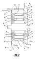
- Figure 2 is a cross sectional view of the parking brake assembly according to one embodiment
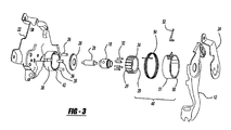
- Figure 3 is an exploded perspective view of the parking brake assembly
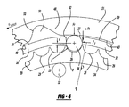
- Figure 4 is an enlarged partial side view of the clutch and lock-release mechanism
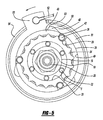
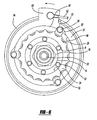
- Figure 5 is a side view of the clutch and lock-release mechanism cutaway to show the lock-release mechanism in a locked position
- Figure 6 is a side view of the clutch and lock-release mechanism cutaway to show the lock-release mechanism in an unlocked position
- Figure 7 is an exploded perspective view of the parking brake assembly according to a second embodiment
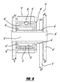
- Figure 8 is a cross sectional view of the clutch and lock-release mechanism according to the second embodiment.
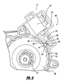
- Figure 9 is a side view of the clutch and lock-release mechanism according to a third embodiment, shown in the locked position.
- a parking brake assembly is generally indicated at 10.
- the parking brake assembly 10 includes a lever 12, a rotary clutch 8 coupled with the lever 12 and a lock-release mechanism 16 coupled with the rotary clutch 8. Described in greater detail below, the rotary clutch 8 allows the lever 12 to be moved from a released position to an actuated position, locked in the actuated position, and selectively unlocked from the actuated position and returned to the released position.
- the parking brake assembly 10 may be any suitable brake actuation device, such as a pedal type, hand type, electronic type, push to release, pull to release, self adjust or cable type parking brake actuator.
- the parking brake assembly 10 is shown as a pedal type brake actuation device utilizing a foot-actuated lever 12. If the parking brake assembly 10 is used for a cable-driven parking brake system, then the lever 12 may be coupled to a cable via a cable connector 14.
- the lever 12 may be movably or pivotally supported in the system in any suitable manner. In the illustrated embodiment, the lever 12 is fixedly secured to a sleeve or pivot 18 that is, in turn, pivotally coupled to a pivot shaft 20 having ends fixedly connected to supports 22, 24.
- the lever 12 moves together with the main pivot 18 about the pivot shaft 20.
- the main pivot 18 and pivot shaft 20 may be supported in any suitable manner, such as by a pedal box, bracket, other frame member, using multiple shafts, etc.
- the main pivot 18, as shown, extends into the lever 12 and is fixedly secured thereto for movement therewith about the pivot shaft.
- the main pivot 18 may be made formed integrally with the lever 12.
- a rotary clutch 8 can allow a suitable holding force at a radius closer to the center of the axis of rotation 25 with little to no brake lever travel loss on apply.
- the clutch contact point can be positioned within one inch or less of the axis of rotation 25 ( Figure 2) of the main pivot 18 or lever 12. This ability is particularly advantageous when used in a foot pedal controlled parking brake, as now the overall packaging can be reduced and still allow for adequate holding force of an actuated parking brake with reduced lever travel loss.
- the rotary clutch 8 is positioned to directly engage and impinge upon an outer cylindrical surface 19 of the main pivot 18.
- the rotary clutch 8 may also be positioned in alternative positions not directly engaging the main pivot 18, such as on another member that is linked to the main pivot 18, such as a secondary pivot or to the lever 12, etc.
- a preferred rotary clutch 8 has 0.1 mm or less return or slop, more preferably has less than 0.05 mm, and most preferably has less than 0.01 mm.
- rotary clutches 8 examples include roller clutches, sprag clutches, frictional clutches, etc.
- the rotary clutch 8 is provided as a roller clutch having one or more unidirectional roller members 32.
- An advantage of a roller clutch 8 is that the roller clutch 8 can allow precise, smooth or non-ratcheting movement of a controlled member in one direction, while preventing rotary movement of the controlled member in an opposite locking direction.
- the roller clutch 8 includes a roller support 34 for supporting the one or more roller members 32.
- the roller members 32 may be positioned between a suitable surface of the roller support 34 and a bearing surface of an adjacent component to be controlled, such as the main pivot 18.
- the roller members 32 are disposed between the outer cylindrical surface 19 of the main pivot 18 and an inside circumferential surface 33 of the roller support 34.
- the roller members 32 may be engagable with notches (not shown) formed along the inside circumferential surface 33 of the roller support 34. The notches would allow the roller members 32 to rotate in one direction to allow rotation of the main pivot 18 relative to the roller support 34 and wedge or lock in an opposite locking direction to prevent rotation of the main pivot 18 relative to the roller support 34.
- springs (not shown) may be used to bias the roller members 32 out of the wedged or locked state.
- the rotary clutch 8 may be substantially coaxially aligned with the main pivot 18.
- the rotary clutch 8 allows for free rotation of the main pivot 18 in a moving direction (such as when the lever 12 is moved by a user to engage the parking brake assembly 10) and prevents return of the main pivot 18 (and lever 12) in the opposite locking direction.
- the rotary clutch 8 may be used in combination with a lock-release mechanism 16.
- a rotary clutch 8 in combination with a lock-release mechanism 16 can allow unidirectional movement of a pivot 18 (or some other controlled member) when the lock-release mechanism 16 is engaged, and rotation of the rotary clutch 8 (i.e.
- a preferred rotary clutch 8 and lock-release mechanism 16 permits primary cable travel loss of 1 mm or less. In one aspect the primary cable travel loss may be less than 0.5 mm and in another aspect less than 0.15 mm.
- the lock-release mechanism 16 may be any suitable engagement / disengagement member or device for locking and releasing a controlled member.
- the lock-release mechanism 16 may be manually or power actuated.
- a controlled member can be any of, one or more, temporarily constrained element(s), such as a pinion, housing , support, pivot, link, shaft, adapter, adapter for attachment to a roller clutch, a roller support, etc.
- the controlled member is the clutch 8.
- the lock-release mechanism 16 includes a block 36 engagable with any one of a plurality of notches 29 on the outer circumference 35 of the roller support 34.
- the blocks 36 are provided as cylindrically shaped pins.
- the blocks 36' may be provided as balls rather than pins as in the first embodiment.
- the lock-release mechanism 16 includes a guide member 38 for locating and movably supporting the block 36.
- the guide member 38 may be any suitable position fixing device, such as a bearing, block, strap, flange, housing, etc.
- the guide member 38 in the illustrated embodiment is a bell housing with a flange adapted for attaching the guide member 38 to a suitable support in the vehicle, such as the pedal box or brackets.
- the guide member 38 may be attached to a suitable support by any suitable means, including welding, rivets, bots, screws, adhesives, etc.
- the guide member 38 preferably has a bearing surface 39. In the illustrated embodiment, the bearing surface 39 is generally cylindrical.
- the guide member 38 preferably includes a check 42 for allowing location of the block 36.
- the check 42 in this example is in the form of a pass-through slot in the guide member 38. While three slots 42 are shown in the pictured embodiment of Figure 3, it should be realized that any number of slots 42 may be utilized, depending generally on the requirements of a specific application.
- the slots 42 are illustratively equally spaced circumferentially about the circumference of the guide member 38.
- the lock-release mechanism 16 also includes an actuator 40.
- the actuator 40 may be any suitable actuating member or device for engaging and disengaging the lock-release mechanism 16 and may be manually actuated or powered.
- the actuator 40 engages the block 36 with a force vector or force that is non-normal to a torque load applied to some controlled member (e.g. the clutch 8).
- some controlled member e.g. the clutch 8
- the force required by the actuator 40 to engage the block 36 can be reduced.
- the force F Release needed to initiate the actuator may be generally seen as a component of the radial force Fr multiplied by the coefficient of friction ⁇ .
- the force Fr is a function of the force F of the block 36 in relation to the controlled member 8 and the distance d from the center of the block 36 to the controlled member 8.
- the force Fr needed to keep the block 36 in place will be a function of the torque ( ⁇ ) applied to the controlled member 36.
- the force Fr may be reduced as the angle between Ft and F is reduced.
- the angle may be reduced in any suitable manner.
- the angle is preferably reduced by using one or more curved bearing surfaces.
- the block 36 may include a curved bearing surface 37 or the actuator 40 may have a curved or angled bearing surface 53 or both.
- the one or more bearing surface(s) 37, 53 are preferably curved or angled such that when a torque ( ⁇ ) is applied to some controlled member 8 (either directly or through a pivot) the force transferred by the controlled member 8 acts on the actuator 40 through the block 36.
- the actuator 40 preferably has an adjuster 48 for moving the block 36 in and out of engagement with the notches 29 in the roller support 34.
- the adjuster 48 may be in any suitable form, such as a cam, detent, surface relief, hole, mound, etc.
- the adjuster 48 is an annular member or ring 51 having a bearing surface 49 for contacting the block 36 and retaining the block 36 engaged with one of the notches 29 to lock the roller support 34 relative to the ring 51.
- a recess or relief 50 is formed along the bearing surface 49 and is sized to receive at least a portion of the block 36 therein.
- the relief 50 includes an arched bearing surface 53 spaced radially relative to the bearing surface 49.
- the ring 51 allows selective engagement and retention of the block 36 with the notches 29 in the roller support 34 by rotation of the ring 51 in one direction toward a locked position, as shown in Figures 4 and 5, and disengagement of the block 36 from the notches 29 by rotation of the ring 51 in an opposite direction toward an unlocked position, as shown in Figure 6. More specifically, in the locked position, the block 36 is disposed in the slot 42 and partially extends beyond the guide member 38 into a corresponding notch 29 of roller support 34, thereby preventing rotation of the roller support 34 relative to the guide member 38. Any forces tending to displace the block 36 from the corresponding notch 29 are resisted by immediate contact of the block 36 with the bearing surface 49.
- the engaging force delivered by the actuator 40 to the block 36 is preferably delivered at a vector non-normal to the torque load applied to the roller support 34.
- a vector non-normal to the torque load applied to the roller support 34 is a force load applied by the main pivot 18.
- the ring 51 is rotated to the unlocked position, wherein the relief 50 in the bearing surface 49 is substantially rotatably aligned with the slot 42 and the block 36 disposed in the slot 42.
- the block 36 is then radially displaceable from the notch 29 into the relief 50.
- Rotation of the roller support 34 causes displacement of the block 36 out of the notch 29 and into the relief 50 in the ring 51.
- the roller support 34 becomes freely rotatable relative to the guide member 38 once the block 36 is fully displaced from the notch 29.
- the actuating mechanism is shown illustratively to include a cable 52 adapted to be coupled to a receiver 55 on the adjuster ring 51.
- the cable 52 can be pulled to move the ring 51 to the unlocked position.
- the cable 52 may be pulled manually or by powered actuators, such as solenoids, linear actuators, rods, cables, springs, magnets, etc.
- a powered actuator may be directly coupled to the adjuster 48 for locking and unlocking the lock-release mechanism 16.
- the lock-release mechanism 16 may also include a biasing member 54 to bias the actuator 40 in one or more directions, such as toward the locked position. As illustrated, the biasing member 54 biases the ring 51 of the actuator 40 toward the locked position (indicated by the arrow in Figures 5 and 6). Thus, the ring 51 may be actuated toward the unlocked position by overcoming the biasing force applied by the biasing member 54.
- a user may actuate the parking brake 10 by moving the lever 12 toward any one of plurality of acuated positions, which is illustrated by the dashed lines in Figure 1.
- the rollers 32 of the roller clutch 8 allow rotation of the main pivot 18 in one direction relative to the locked and fixed roller support 34, but prevent back motion of the main pivot 18 in the opposite direction.
- the lever 12 and main pivot 18 can rotate unidirectionally on the rollers 32 of the roller clutch 8.
- the user can pull the cable 52 to move the ring 51 to toward the unlocked position.
- the relief 50 is generally aligned with an associated block 36 to allow the block 36 to move out of fixing engagement with one of the notches 29 in the roller support 34, thereby allowing the roller clutch 8 and main pivot 18 to rotate together and return the lever 12 from the actuated position to the released and resting position shown by the solid lines in Figure 1.
- the lever 12 may be returned to the released and resting position by a conventional lever biasing member (not shown).
- FIG. 9 another embodiment of a lock-release mechanism is indicated at 16 and shown in the locked position.
- the lock release mechanism 16 includes a lock-release member 300, a fixed member 310, a movable block 312 fixed radially in position to the fixed member 310 and a powered actuator 314 for moving the block 312.
- the block 312, fixed radially in position in this example, is fixed by residing in a pass through slot 324 of the fixed member 310.
- the powered actuator 314 may be any suitable powered actuation device, such as electrical, pneumatic, hydraulic, magnetic, etc.
- the powered actuator as shown includes a solenoid 316, a movable member 318 coupled with the solenoid 316 and a bearing surface 320 coupled with the movable member 318.
- the bearing surface 320 of the movable member 318 may be used for contacting the bearing surface 308 of the block 312.
- the bearing surface 308 of the block 312 is preferably curved.
- the controlled member 326 is a pinion 327.
- the pinion 327 is coupled with a notched body 328 with the notches 330, 332 that are sized to receive at least a portion of the block 312.
- the solenoid 316 is activated to extend the moveable member 318 and the bearing surface 320 against the block 312 and force the block 312 into engagement with one or more notches 320, 322 of the controlled member 326.
- the block 312 may be disengaged from the one or more notches 320, 322 by deactivating the solenoid 316.
- the engagement force is preferably delivered at a vector or force that is non-normal to a torque applied to the controlled member 326.
Landscapes
- Engineering & Computer Science (AREA)
- Transportation (AREA)
- Mechanical Engineering (AREA)
- Braking Elements And Transmission Devices (AREA)
- Braking Arrangements (AREA)
- Mechanical Operated Clutches (AREA)
- Mechanical Control Devices (AREA)
Applications Claiming Priority (2)
| Application Number | Priority Date | Filing Date | Title |
|---|---|---|---|
| US82278806P | 2006-08-18 | 2006-08-18 | |
| US11/830,414 US9139169B2 (en) | 2006-08-18 | 2007-07-30 | Release mechanism for a parking brake clutch |
Publications (3)
| Publication Number | Publication Date |
|---|---|
| EP1889763A2 true EP1889763A2 (de) | 2008-02-20 |
| EP1889763A3 EP1889763A3 (de) | 2008-02-27 |
| EP1889763B1 EP1889763B1 (de) | 2009-08-05 |
Family
ID=38698298
Family Applications (1)
| Application Number | Title | Priority Date | Filing Date |
|---|---|---|---|
| EP07114546A Not-in-force EP1889763B1 (de) | 2006-08-18 | 2007-08-17 | Freigabemechanismus für eine Parkbremsenkupplung |
Country Status (7)
| Country | Link |
|---|---|
| US (1) | US9139169B2 (de) |
| EP (1) | EP1889763B1 (de) |
| JP (1) | JP2008056237A (de) |
| KR (1) | KR20080016499A (de) |
| CN (1) | CN101125546B (de) |
| AT (1) | ATE438545T1 (de) |
| DE (1) | DE602007001842D1 (de) |
Cited By (1)
| Publication number | Priority date | Publication date | Assignee | Title |
|---|---|---|---|---|
| DE102018108596A1 (de) * | 2018-04-11 | 2019-10-17 | Gkn Automotive Ltd. | Parksperreneinheit und Getriebeanordnung mit einer solchen Parksperreneinheit |
Families Citing this family (7)
| Publication number | Priority date | Publication date | Assignee | Title |
|---|---|---|---|---|
| US9827954B2 (en) * | 2006-08-18 | 2017-11-28 | Dura Operating, Llc | Release mechanism for a parking brake clutch |
| DE102009021923A1 (de) * | 2009-04-08 | 2010-10-14 | Schaeffler Technologies Gmbh & Co. Kg | Handbetätigter Freilaufkupplungs-Feststellbremsenaktuator |
| DE102010007913B4 (de) * | 2010-02-13 | 2014-04-03 | Audi Ag | Drehsteller |
| US8852041B2 (en) * | 2010-09-30 | 2014-10-07 | Shimano, Inc. | Bicycle derailleur with rotation resistance |
| US9845083B2 (en) * | 2015-07-01 | 2017-12-19 | Dura Operating, Llc | Park brake control assembly |
| CN107512353B (zh) * | 2016-06-16 | 2019-10-15 | 稳正企业股份有限公司 | 手刹车结构 |
| DE102018118305A1 (de) * | 2018-07-27 | 2020-01-30 | Stopfix Bremse Schröter & Co. GmbH | Vorrichtung und Verfahren zur Betätigung einer Feststellbremse |
Family Cites Families (26)
| Publication number | Priority date | Publication date | Assignee | Title |
|---|---|---|---|---|
| US2063379A (en) * | 1931-03-27 | 1936-12-08 | Borg Warner | Overrunning clutch and control means therefor |
| US2884805A (en) * | 1956-06-22 | 1959-05-05 | Chicago Forging & Mfg Co | Control mechanism |
| US3011606A (en) * | 1957-07-26 | 1961-12-05 | Borg Warner | Roller clutch |
| US2935895A (en) * | 1957-11-13 | 1960-05-10 | Chicago Forging & Mfg Co | Auxiliary brake and release |
| GB943622A (en) | 1960-03-16 | 1963-12-04 | Chicago Forging & Mfg Co | Improvements in or relating to brake control mechanisms |
| US3648813A (en) * | 1970-02-24 | 1972-03-14 | Gen Motors Corp | Automatic clutch-wear compensator |
| JPS57194143A (en) * | 1981-05-22 | 1982-11-29 | Toyota Motor Corp | Braking force holder for car |
| EP0112112A1 (de) * | 1982-12-14 | 1984-06-27 | Michel Deal | Getriebe mit veränderbarem Übersetzungsverhältnis |
| US4762332A (en) | 1986-06-17 | 1988-08-09 | Byung D. Yim | Wheel chair |
| GB9025041D0 (en) * | 1990-11-17 | 1991-01-02 | Bunker Gavin | Mechanism for actuating a vehicle parking brake |
| US5467666A (en) * | 1994-07-07 | 1995-11-21 | Dura Automotive Systems, Inc. | Non-jamming self-adjust pawl and ratchet mechanism |
| US5528956A (en) * | 1994-11-08 | 1996-06-25 | Atwood Industries, Inc. | Vehicular parking brake control with stored energy assist for applying the brake |
| US5547055A (en) | 1995-01-12 | 1996-08-20 | Chin-Fa Chen | Unidirectional roller bearing with roller retaining structure |
| US5794492A (en) * | 1996-02-28 | 1998-08-18 | Dura Automotive Systems, Inc. | Parking brake usable as emergency brake |
| US5832784A (en) * | 1997-03-18 | 1998-11-10 | Dura Automotive Systems, Inc. | Variable ratio parking brake control with enhanced cable take-up |
| US6282980B1 (en) * | 1999-09-23 | 2001-09-04 | Ventra Group Inc. | Self-adjusting parking brake actuator |
| KR100341294B1 (ko) * | 2000-08-16 | 2002-06-22 | 이충곤 | 자동차 주차브레이크의 케이블 장력조절장치 |
| US6745882B2 (en) | 2001-12-27 | 2004-06-08 | The Timken Company | Locking clutch |
| US6902046B1 (en) | 2002-03-21 | 2005-06-07 | Sonnax Industries, Inc. | High performance sprag clutch assembly |
| JP4300392B2 (ja) * | 2002-06-27 | 2009-07-22 | 株式会社ジェイテクト | 一方クラッチ |
| US6997295B2 (en) | 2002-07-03 | 2006-02-14 | Pederson Jack E | Clutch having elements capable of independent operation |
| KR100461609B1 (ko) * | 2003-10-30 | 2004-12-13 | 경창산업주식회사 | 브레이크 케이블 장력 조절 기구를 포함하는 주차 브레이크 |
| US7574943B2 (en) * | 2005-06-01 | 2009-08-18 | Dura Global Technologies, Inc. | Parking brake actuator with clutch spring assembly |
| US9827954B2 (en) * | 2006-08-18 | 2017-11-28 | Dura Operating, Llc | Release mechanism for a parking brake clutch |
| US8025129B2 (en) * | 2008-01-25 | 2011-09-27 | Schaeffler Kg | Overrunning clutch parking brake actuator |
| DE102009021923A1 (de) * | 2009-04-08 | 2010-10-14 | Schaeffler Technologies Gmbh & Co. Kg | Handbetätigter Freilaufkupplungs-Feststellbremsenaktuator |
-
2007
- 2007-07-30 US US11/830,414 patent/US9139169B2/en not_active Expired - Fee Related
- 2007-08-17 AT AT07114546T patent/ATE438545T1/de not_active IP Right Cessation
- 2007-08-17 DE DE602007001842T patent/DE602007001842D1/de active Active
- 2007-08-17 CN CN2007101526423A patent/CN101125546B/zh not_active Expired - Fee Related
- 2007-08-17 EP EP07114546A patent/EP1889763B1/de not_active Not-in-force
- 2007-08-17 KR KR1020070082843A patent/KR20080016499A/ko not_active Withdrawn
- 2007-08-20 JP JP2007240168A patent/JP2008056237A/ja active Pending
Cited By (3)
| Publication number | Priority date | Publication date | Assignee | Title |
|---|---|---|---|---|
| DE102018108596A1 (de) * | 2018-04-11 | 2019-10-17 | Gkn Automotive Ltd. | Parksperreneinheit und Getriebeanordnung mit einer solchen Parksperreneinheit |
| DE102018108596B4 (de) | 2018-04-11 | 2022-01-05 | Gkn Automotive Limited | Parksperreneinheit und Getriebeanordnung mit einer solchen Parksperreneinheit |
| US11248702B2 (en) | 2018-04-11 | 2022-02-15 | Gkn Automotive Ltd. | Parking lock unit and transmission assembly therefor |
Also Published As
| Publication number | Publication date |
|---|---|
| JP2008056237A (ja) | 2008-03-13 |
| KR20080016499A (ko) | 2008-02-21 |
| DE602007001842D1 (de) | 2009-09-17 |
| CN101125546B (zh) | 2011-12-21 |
| US20080041185A1 (en) | 2008-02-21 |
| EP1889763B1 (de) | 2009-08-05 |
| US9139169B2 (en) | 2015-09-22 |
| EP1889763A3 (de) | 2008-02-27 |
| ATE438545T1 (de) | 2009-08-15 |
| CN101125546A (zh) | 2008-02-20 |
Similar Documents
| Publication | Publication Date | Title |
|---|---|---|
| EP1889763B1 (de) | Freigabemechanismus für eine Parkbremsenkupplung | |
| US4819501A (en) | Self-adjusting brake mechanism | |
| EP3460280B1 (de) | Kupplungseinheit | |
| CN104930186B (zh) | 用于机动车辆变速器的驻车机构装置 | |
| EP0069207B1 (de) | Sitzverstellvorrichtung | |
| CN102313009B (zh) | 用于机动车的动力传动系的驻车闭锁总成 | |
| US6516931B2 (en) | Freewheel clutch | |
| EP3069938B1 (de) | Sitzgurtvorrichtung | |
| US10520046B2 (en) | Low backlash multimode clutch | |
| JP6232647B2 (ja) | 車両用ペダル装置 | |
| EP1562784B1 (de) | Zwei-weg verriegelbare antriebskupplung | |
| US7114778B2 (en) | Drive having a sliding element for a vehicle seat adjuster | |
| US20060201267A1 (en) | Multiple turn mechanism for manual lumbar support adjustment | |
| US6282980B1 (en) | Self-adjusting parking brake actuator | |
| EP2039572B1 (de) | Freigabemechanismus für eine Feststellbremsenkupplung | |
| US6651793B2 (en) | Power-split transmission with a controllable friction clutch | |
| US9827954B2 (en) | Release mechanism for a parking brake clutch | |
| EP1728698B1 (de) | Feststellbremsbetätigung mit Klemmfederbaugruppe | |
| CN117280142A (zh) | 用于驻车锁的致动器 | |
| US20060070485A1 (en) | Brake actuating assembly for a vehicle | |
| GB2059522A (en) | Synchronising means for engaging a reverse gear ratio | |
| EP0157027B1 (de) | Vorrichtung zur Erhöhung der Sicherheit der Parksperre eines automatischen Getriebes | |
| EP1163125B1 (de) | Handverstellmechanismus für fahrzeuge | |
| US20090101455A1 (en) | Self-adjusting torsion lock parking brake | |
| CZ412298A3 (cs) | Upevňovací zařízení pro ruční brzdu |
Legal Events
| Date | Code | Title | Description |
|---|---|---|---|
| PUAI | Public reference made under article 153(3) epc to a published international application that has entered the european phase |
Free format text: ORIGINAL CODE: 0009012 |
|
| PUAL | Search report despatched |
Free format text: ORIGINAL CODE: 0009013 |
|
| AK | Designated contracting states |
Kind code of ref document: A2 Designated state(s): AT BE BG CH CY CZ DE DK EE ES FI FR GB GR HU IE IS IT LI LT LU LV MC MT NL PL PT RO SE SI SK TR |
|
| AX | Request for extension of the european patent |
Extension state: AL BA HR MK YU |
|
| AK | Designated contracting states |
Kind code of ref document: A3 Designated state(s): AT BE BG CH CY CZ DE DK EE ES FI FR GB GR HU IE IS IT LI LT LU LV MC MT NL PL PT RO SE SI SK TR |
|
| AX | Request for extension of the european patent |
Extension state: AL BA HR MK YU |
|
| RIC1 | Information provided on ipc code assigned before grant |
Ipc: G05G 1/14 20060101ALI20080118BHEP Ipc: B60T 7/06 20060101AFI20071128BHEP Ipc: B60T 7/04 20060101ALI20080118BHEP Ipc: B60T 7/10 20060101ALI20080118BHEP |
|
| 17P | Request for examination filed |
Effective date: 20080819 |
|
| AKX | Designation fees paid |
Designated state(s): AT BE BG CH CY CZ DE DK EE ES FI FR GB GR HU IE IS IT LI LT LU LV MC MT NL PL PT RO SE SI SK TR |
|
| GRAP | Despatch of communication of intention to grant a patent |
Free format text: ORIGINAL CODE: EPIDOSNIGR1 |
|
| RIC1 | Information provided on ipc code assigned before grant |
Ipc: B60T 7/04 20060101ALI20090212BHEP Ipc: B60T 7/10 20060101ALI20090212BHEP Ipc: G05G 1/30 20080401ALI20090212BHEP Ipc: B60T 7/06 20060101AFI20090212BHEP |
|
| GRAS | Grant fee paid |
Free format text: ORIGINAL CODE: EPIDOSNIGR3 |
|
| GRAA | (expected) grant |
Free format text: ORIGINAL CODE: 0009210 |
|
| AK | Designated contracting states |
Kind code of ref document: B1 Designated state(s): AT BE BG CH CY CZ DE DK EE ES FI FR GB GR HU IE IS IT LI LT LU LV MC MT NL PL PT RO SE SI SK TR |
|
| REG | Reference to a national code |
Ref country code: GB Ref legal event code: FG4D |
|
| REG | Reference to a national code |
Ref country code: CH Ref legal event code: EP |
|
| REG | Reference to a national code |
Ref country code: IE Ref legal event code: FG4D |
|
| REF | Corresponds to: |
Ref document number: 602007001842 Country of ref document: DE Date of ref document: 20090917 Kind code of ref document: P |
|
| LTIE | Lt: invalidation of european patent or patent extension |
Effective date: 20090805 |
|
| PG25 | Lapsed in a contracting state [announced via postgrant information from national office to epo] |
Ref country code: SE Free format text: LAPSE BECAUSE OF FAILURE TO SUBMIT A TRANSLATION OF THE DESCRIPTION OR TO PAY THE FEE WITHIN THE PRESCRIBED TIME-LIMIT Effective date: 20090805 Ref country code: LT Free format text: LAPSE BECAUSE OF FAILURE TO SUBMIT A TRANSLATION OF THE DESCRIPTION OR TO PAY THE FEE WITHIN THE PRESCRIBED TIME-LIMIT Effective date: 20090805 Ref country code: IS Free format text: LAPSE BECAUSE OF FAILURE TO SUBMIT A TRANSLATION OF THE DESCRIPTION OR TO PAY THE FEE WITHIN THE PRESCRIBED TIME-LIMIT Effective date: 20091205 Ref country code: FI Free format text: LAPSE BECAUSE OF FAILURE TO SUBMIT A TRANSLATION OF THE DESCRIPTION OR TO PAY THE FEE WITHIN THE PRESCRIBED TIME-LIMIT Effective date: 20090805 Ref country code: AT Free format text: LAPSE BECAUSE OF FAILURE TO SUBMIT A TRANSLATION OF THE DESCRIPTION OR TO PAY THE FEE WITHIN THE PRESCRIBED TIME-LIMIT Effective date: 20090805 Ref country code: ES Free format text: LAPSE BECAUSE OF FAILURE TO SUBMIT A TRANSLATION OF THE DESCRIPTION OR TO PAY THE FEE WITHIN THE PRESCRIBED TIME-LIMIT Effective date: 20091116 |
|
| NLV1 | Nl: lapsed or annulled due to failure to fulfill the requirements of art. 29p and 29m of the patents act | ||
| PG25 | Lapsed in a contracting state [announced via postgrant information from national office to epo] |
Ref country code: LV Free format text: LAPSE BECAUSE OF FAILURE TO SUBMIT A TRANSLATION OF THE DESCRIPTION OR TO PAY THE FEE WITHIN THE PRESCRIBED TIME-LIMIT Effective date: 20090805 Ref country code: PL Free format text: LAPSE BECAUSE OF FAILURE TO SUBMIT A TRANSLATION OF THE DESCRIPTION OR TO PAY THE FEE WITHIN THE PRESCRIBED TIME-LIMIT Effective date: 20090805 Ref country code: NL Free format text: LAPSE BECAUSE OF FAILURE TO SUBMIT A TRANSLATION OF THE DESCRIPTION OR TO PAY THE FEE WITHIN THE PRESCRIBED TIME-LIMIT Effective date: 20090805 Ref country code: SI Free format text: LAPSE BECAUSE OF FAILURE TO SUBMIT A TRANSLATION OF THE DESCRIPTION OR TO PAY THE FEE WITHIN THE PRESCRIBED TIME-LIMIT Effective date: 20090805 |
|
| PG25 | Lapsed in a contracting state [announced via postgrant information from national office to epo] |
Ref country code: BG Free format text: LAPSE BECAUSE OF FAILURE TO SUBMIT A TRANSLATION OF THE DESCRIPTION OR TO PAY THE FEE WITHIN THE PRESCRIBED TIME-LIMIT Effective date: 20091105 Ref country code: PT Free format text: LAPSE BECAUSE OF FAILURE TO SUBMIT A TRANSLATION OF THE DESCRIPTION OR TO PAY THE FEE WITHIN THE PRESCRIBED TIME-LIMIT Effective date: 20091205 Ref country code: MC Free format text: LAPSE BECAUSE OF NON-PAYMENT OF DUE FEES Effective date: 20090831 |
|
| PG25 | Lapsed in a contracting state [announced via postgrant information from national office to epo] |
Ref country code: CZ Free format text: LAPSE BECAUSE OF FAILURE TO SUBMIT A TRANSLATION OF THE DESCRIPTION OR TO PAY THE FEE WITHIN THE PRESCRIBED TIME-LIMIT Effective date: 20090805 Ref country code: DK Free format text: LAPSE BECAUSE OF FAILURE TO SUBMIT A TRANSLATION OF THE DESCRIPTION OR TO PAY THE FEE WITHIN THE PRESCRIBED TIME-LIMIT Effective date: 20090805 Ref country code: RO Free format text: LAPSE BECAUSE OF FAILURE TO SUBMIT A TRANSLATION OF THE DESCRIPTION OR TO PAY THE FEE WITHIN THE PRESCRIBED TIME-LIMIT Effective date: 20090805 Ref country code: EE Free format text: LAPSE BECAUSE OF FAILURE TO SUBMIT A TRANSLATION OF THE DESCRIPTION OR TO PAY THE FEE WITHIN THE PRESCRIBED TIME-LIMIT Effective date: 20090805 |
|
| PG25 | Lapsed in a contracting state [announced via postgrant information from national office to epo] |
Ref country code: SK Free format text: LAPSE BECAUSE OF FAILURE TO SUBMIT A TRANSLATION OF THE DESCRIPTION OR TO PAY THE FEE WITHIN THE PRESCRIBED TIME-LIMIT Effective date: 20090805 |
|
| PLBE | No opposition filed within time limit |
Free format text: ORIGINAL CODE: 0009261 |
|
| STAA | Information on the status of an ep patent application or granted ep patent |
Free format text: STATUS: NO OPPOSITION FILED WITHIN TIME LIMIT |
|
| PG25 | Lapsed in a contracting state [announced via postgrant information from national office to epo] |
Ref country code: BE Free format text: LAPSE BECAUSE OF FAILURE TO SUBMIT A TRANSLATION OF THE DESCRIPTION OR TO PAY THE FEE WITHIN THE PRESCRIBED TIME-LIMIT Effective date: 20090805 |
|
| 26N | No opposition filed |
Effective date: 20100507 |
|
| PG25 | Lapsed in a contracting state [announced via postgrant information from national office to epo] |
Ref country code: IE Free format text: LAPSE BECAUSE OF NON-PAYMENT OF DUE FEES Effective date: 20090817 |
|
| PG25 | Lapsed in a contracting state [announced via postgrant information from national office to epo] |
Ref country code: GR Free format text: LAPSE BECAUSE OF FAILURE TO SUBMIT A TRANSLATION OF THE DESCRIPTION OR TO PAY THE FEE WITHIN THE PRESCRIBED TIME-LIMIT Effective date: 20091106 |
|
| PGFP | Annual fee paid to national office [announced via postgrant information from national office to epo] |
Ref country code: DE Payment date: 20100827 Year of fee payment: 4 Ref country code: FR Payment date: 20100831 Year of fee payment: 4 |
|
| PG25 | Lapsed in a contracting state [announced via postgrant information from national office to epo] |
Ref country code: IT Free format text: LAPSE BECAUSE OF FAILURE TO SUBMIT A TRANSLATION OF THE DESCRIPTION OR TO PAY THE FEE WITHIN THE PRESCRIBED TIME-LIMIT Effective date: 20090805 |
|
| PG25 | Lapsed in a contracting state [announced via postgrant information from national office to epo] |
Ref country code: LU Free format text: LAPSE BECAUSE OF NON-PAYMENT OF DUE FEES Effective date: 20090817 Ref country code: MT Free format text: LAPSE BECAUSE OF FAILURE TO SUBMIT A TRANSLATION OF THE DESCRIPTION OR TO PAY THE FEE WITHIN THE PRESCRIBED TIME-LIMIT Effective date: 20090805 |
|
| PG25 | Lapsed in a contracting state [announced via postgrant information from national office to epo] |
Ref country code: HU Free format text: LAPSE BECAUSE OF FAILURE TO SUBMIT A TRANSLATION OF THE DESCRIPTION OR TO PAY THE FEE WITHIN THE PRESCRIBED TIME-LIMIT Effective date: 20100206 |
|
| PG25 | Lapsed in a contracting state [announced via postgrant information from national office to epo] |
Ref country code: TR Free format text: LAPSE BECAUSE OF FAILURE TO SUBMIT A TRANSLATION OF THE DESCRIPTION OR TO PAY THE FEE WITHIN THE PRESCRIBED TIME-LIMIT Effective date: 20090805 |
|
| PG25 | Lapsed in a contracting state [announced via postgrant information from national office to epo] |
Ref country code: CY Free format text: LAPSE BECAUSE OF FAILURE TO SUBMIT A TRANSLATION OF THE DESCRIPTION OR TO PAY THE FEE WITHIN THE PRESCRIBED TIME-LIMIT Effective date: 20090805 |
|
| REG | Reference to a national code |
Ref country code: CH Ref legal event code: PL |
|
| GBPC | Gb: european patent ceased through non-payment of renewal fee |
Effective date: 20110817 |
|
| PG25 | Lapsed in a contracting state [announced via postgrant information from national office to epo] |
Ref country code: CH Free format text: LAPSE BECAUSE OF NON-PAYMENT OF DUE FEES Effective date: 20110831 Ref country code: LI Free format text: LAPSE BECAUSE OF NON-PAYMENT OF DUE FEES Effective date: 20110831 |
|
| REG | Reference to a national code |
Ref country code: FR Ref legal event code: ST Effective date: 20120430 |
|
| REG | Reference to a national code |
Ref country code: DE Ref legal event code: R119 Ref document number: 602007001842 Country of ref document: DE Effective date: 20120301 |
|
| PG25 | Lapsed in a contracting state [announced via postgrant information from national office to epo] |
Ref country code: FR Free format text: LAPSE BECAUSE OF NON-PAYMENT OF DUE FEES Effective date: 20110831 Ref country code: GB Free format text: LAPSE BECAUSE OF NON-PAYMENT OF DUE FEES Effective date: 20110817 |
|
| PG25 | Lapsed in a contracting state [announced via postgrant information from national office to epo] |
Ref country code: DE Free format text: LAPSE BECAUSE OF NON-PAYMENT OF DUE FEES Effective date: 20120301 |