EP1889802A2 - Dispositif de carrousel pour transporter des récipients - Google Patents
Dispositif de carrousel pour transporter des récipients Download PDFInfo
- Publication number
- EP1889802A2 EP1889802A2 EP07113829A EP07113829A EP1889802A2 EP 1889802 A2 EP1889802 A2 EP 1889802A2 EP 07113829 A EP07113829 A EP 07113829A EP 07113829 A EP07113829 A EP 07113829A EP 1889802 A2 EP1889802 A2 EP 1889802A2
- Authority
- EP
- European Patent Office
- Prior art keywords
- carrousel
- stabilising
- head
- shaft
- support disc
- Prior art date
- Legal status (The legal status is an assumption and is not a legal conclusion. Google has not performed a legal analysis and makes no representation as to the accuracy of the status listed.)
- Granted
Links
Images


Classifications
-
- B—PERFORMING OPERATIONS; TRANSPORTING
- B65—CONVEYING; PACKING; STORING; HANDLING THIN OR FILAMENTARY MATERIAL
- B65G—TRANSPORT OR STORAGE DEVICES, e.g. CONVEYORS FOR LOADING OR TIPPING, SHOP CONVEYOR SYSTEMS OR PNEUMATIC TUBE CONVEYORS
- B65G29/00—Rotary conveyors, e.g. rotating discs, arms, star-wheels or cones
-
- B—PERFORMING OPERATIONS; TRANSPORTING
- B65—CONVEYING; PACKING; STORING; HANDLING THIN OR FILAMENTARY MATERIAL
- B65C—LABELLING OR TAGGING MACHINES, APPARATUS, OR PROCESSES
- B65C9/00—Details of labelling machines or apparatus
- B65C9/02—Devices for moving articles, e.g. containers, past labelling station
-
- B—PERFORMING OPERATIONS; TRANSPORTING
- B65—CONVEYING; PACKING; STORING; HANDLING THIN OR FILAMENTARY MATERIAL
- B65G—TRANSPORT OR STORAGE DEVICES, e.g. CONVEYORS FOR LOADING OR TIPPING, SHOP CONVEYOR SYSTEMS OR PNEUMATIC TUBE CONVEYORS
- B65G47/00—Article or material-handling devices associated with conveyors; Methods employing such devices
- B65G47/74—Feeding, transfer, or discharging devices of particular kinds or types
- B65G47/84—Star-shaped wheels or devices having endless travelling belts or chains, the wheels or devices being equipped with article-engaging elements
- B65G47/846—Star-shaped wheels or wheels equipped with article-engaging elements
-
- B—PERFORMING OPERATIONS; TRANSPORTING
- B65—CONVEYING; PACKING; STORING; HANDLING THIN OR FILAMENTARY MATERIAL
- B65G—TRANSPORT OR STORAGE DEVICES, e.g. CONVEYORS FOR LOADING OR TIPPING, SHOP CONVEYOR SYSTEMS OR PNEUMATIC TUBE CONVEYORS
- B65G2201/00—Indexing codes relating to handling devices, e.g. conveyors, characterised by the type of product or load being conveyed or handled
- B65G2201/02—Articles
- B65G2201/0235—Containers
- B65G2201/0244—Bottles
Definitions
- the present invention relates to the technical field concerning automatic packaging machines.
- the present invention relates to a carrousel device for conveying containers, aimed at being installed in an automatic packaging machine, e.g. labelling machine designed to apply a corresponding label to the containers.
- an automatic packaging machine e.g. labelling machine designed to apply a corresponding label to the containers.
- carrousel devices are commonly used in the automatic labelling machines for conveying bottles, already filled with a product, in proximity of a device for applying labels.
- a known type of carrousel conveying device includes a rotating support plate, arranged horizontal and operated by suitable motor means.
- the above mentioned plate carries, mounted peripherally thereon, a plurality of equidistant small plates, aimed at receiving corresponding bottles to be conveyed.
- the bottles are fed to the relative small plates with a time relation, by a linear conveyor, e.g. a screw conveyor, which also suitably spaces them out, so as to synchronise them with the small plates pitch.
- An inlet conveyor disc of the so-called "star” type co-operates in the correct directing of the bottles toward the small plates.
- the disc is mounted rotating on a vertical, axial shaft, so that its peripheral edge is substantially tangential to the circumference covered by the small plates during the support disc rotation.
- Equidistant seats, made along the peripheral edge of the conveyor disc, with the same pitch as the small plates pitch, are aimed at receiving the bottles fed by the screw conveyor and at placing them on a small plate.
- the small plates are mounted rotating on relative vertical stems, which pass through the support plate.
- a brushless motor or a mechanism modifies the orientation of the small plate, so as to present the bottle to the label applying device in a correct labelling orientation.
- An counter-acting head hung over each small plate, has cylindrical symmetry and vertical axis, and rotates likewise in synchrony with the small plate, and is aimed at engaging the upper part of the bottle, so as to keep it in the correct label application position.
- the counter-acting heads idle on their axes, are supported, at bottom, by a big horizontal drum arranged axial with respect to the small plates support disc and above the latter.
- the counter-acting heads are connected to a cam guide mechanism, situated inside the drum, which allows the heads to raise immediately before reaching the bottle engagement position, and to lower to engage the bottle to be labeled, as soon as it is placed on the relative small plate.
- the minimum and maximum height of the counter-acting heads are also made adjustable, so as to adapt them to different sizes of the bottles to be conveyed.
- the labelled bottles are conveyed toward subsequent packaging stations by an outlet conveyor disc, of the so-called "star" type, which is substantially identical with the inlet one, already described, and which picks up the bottles from the corresponding small plates and places them on an outlet conveyor.
- an outlet conveyor disc of the so-called "star” type, which is substantially identical with the inlet one, already described, and which picks up the bottles from the corresponding small plates and places them on an outlet conveyor.
- the drum carrying the counter-acting heads is particularly cumbersome, it can be tainted by the product powders or remnants, and in turn, it can produce powders or other impurities, which can fall on the conveyed containers.
- its raised position with respect to the packaging plane is awkward for the maintenance, it can limit or prevent the operators' total visual control of the packaging machine, and anyway, it makes the conveyor uselessly cumbersome, complicated and heavy.
- the object of the present invention is to propose a carrousel conveyor, which eliminates the above mentioned disadvantages, and which makes it usable in any application field.
- Another object of the invention is to propose a carrousel conveyor of simplified structure, which allows to cut the production and maintenance costs.
- reference numeral 10 indicates a carrousel device for conveying containers 4, obtained according to the present invention.
- the device 10 is aimed at conveying containers of any type and in any application environment, but it is particularly indicated for conveying containers to a work station 100 of an automatic packaging machine, e.g. a labelling station for bottles for pharmaceutical, food and other products.
- the carrousel device 10 includes a support plate 1, arranged horizontal and operated to rotate on its axis by motor means of known type, not shown.
- the support plate 1 has a plurality of small plates 3, arranged equally spaced around a circumference of a given diameter, which is smaller than the maximum diameter of the same plate 1.
- the small plates 3 are mounted on corresponding axial stems 3a (see Figure 2), which penetrate into the support plate 1 and are connected, in known way, to an actuator device 3b, aimed at defining its orientation in relation with rotation of the support plate 1.
- the actuator device 3b can include either a suitable gear group or a motor of brushless type, controlled by a control unit of the carrousel conveyor device 10.
- the small plate 3 is aimed at receiving and carrying a corresponding container 4, resting thereon, toward a work station 100 of the packaging machine, which in the example case consists of a known group for applying labels to the above mentioned containers 4.
- the containers 4 are fed one by one to the carrousel conveyor device 10 by an inlet linear conveyor 110, whose final part includes a screw conveyor 111.
- the latter is driven into rotation in suitable time relation with the conveyor disc and is particularly indicated to canalise the containers 4 one by one and at a mutual distance equal to the pitch between the small plates 3.
- An inlet rotating star conveyor 60 interposed between the screw conveyor 111 and the support disc 1, includes a horizontal disc 61 keyed co-axially onto a corresponding vertical shaft 62 and connected to motor means of known type, which are aimed at driving the horizontal disc 61 into rotation in a direction opposite to the one of the support disc 1 rotation and in time relation with the latter.
- a plurality of seats 63, made in the peripheral edge of the horizontal disc 61, have the same pitch as the small plates 3 and are aimed at engaging the containers 4 coming from the screw conveyor 111 and at conveying them until they engage with a small plate 3.
- a shaped guide plate 65, arranged laterally with respect to the horizontal disc 61, co-operates with the latter in the above function.
- the containers 4 at the outlet of the carrousel device 10 after their passage in a position corresponding to the work station 100, are picked up by the small plate 3 by means of an outlet rotating star conveyor 70, composed of a horizontal, counter-rotating, outlet disc 71, keyed co-axially onto its vertical shaft 72 and having seats 73, aimed at engaging the containers 4 and at carrying them toward an outlet linear conveyor 120, so as to be conveyed toward subsequent work stations of the packaging machine.
- an outlet rotating star conveyor 70 composed of a horizontal, counter-rotating, outlet disc 71, keyed co-axially onto its vertical shaft 72 and having seats 73, aimed at engaging the containers 4 and at carrying them toward an outlet linear conveyor 120, so as to be conveyed toward subsequent work stations of the packaging machine.
- the above mentioned carrousel device 10 includes also, for each small plate 3, a corresponding stabilising head 20, situated above the small plate 3 and aimed at engaging a container 4 after it had been placed on the small plate 3, in accordance with what has been described previously, so as to stabilise its position during the transport.
- each stabilising head 20 includes substantially a tubular element of cylindrical symmetry, which is arranged vertical and has a cavity 21, and which is aimed at being lowered onto the upper part of the container 4 and at receiving, in the cavity, the portion of the container 4 composed of its neck and cap.
- the stabilising head 20 is supported by a cap 25, at an end of the lower surface thereof, with possibility of idle rotation on its axis, by means of a coupling with ball bearing.
- the cap 25 is fastened to the head of a shaft 30, arranged vertical and having its axis substantially parallel to the one of the stabilising head 20.
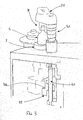
- the shaft 30, extending from the support disc 1 and inside it, is mounted sliding thereon by means of a low friction axial guide block 5, and moves between a raised position A ( Figure 2), in which the stabilising head 20 is at such a level, as not to engage the container 4, and a lowered position B ( Figure 3), in which the container 4 neck and cap are contained in the cavity 21 of the stabilising head 20.
- the shaft 30 raising and lowering steps are defined in suitable time relation with the rotation of the support disc 1.
- Guiding means 32 of the shaft 30, mechanically connected to the latter, are situated inside the support disc 1, so as to define the sliding of the shaft 30 and the level of the head 20 in the above described way.
- the guiding means 32 include a cylindrical cam 33, mounted stationary axially with respect to the support disc 1 and having a close path peripheral guide cam 34.
- the cylindrical cam 33 is also mounted sliding on a plurality of stems 40, to allow the adjustment of its height, and consequently, the adjustment of the minimum and maximum height of the shaft 30. This allows to adapt the carrousel device 10 to different sizes, and in particular to different heights, of the containers 4 to be conveyed.
- a telescopic spring cover 36 arranged externally to the shaft 30, is aimed at hiding the shaft from view, and at protecting the same and the operators.
- the stabilising head 20 is mounted on a spring device 50, aimed at giving the latter a further axial elastic sliding, so as to soften the impact of the stabilising head 20 on the containers 4 during their engagement.
- the container 4 is engaged by a seat 63 of the disc 62 of the inlet star conveyor 60, and is conveyed up to a small plate 3 with the co-operation of a portion of the guide plate 65.
- the stabilising head is carried by the cam 34 to its lowered position B and engages the upper part of the container 4 to stabilise its position on the small plate 3. Due to the support disc 1 rotation, the container 4 is carried to the work station 100, in which for example, a label is applied thereto. The angular position of the container 4 can be changed along the path, so as to place it in best labeling position, by a suitable small plate 3 rotation, which is accompanied by a corresponding idle rotation of the stabilising head 20.
- the container 4 is engaged by the cavity 73 of the latter.
- the stabilising head 20 is brought from the cam 34 back to its raised position and disengages the container 4. Then, the latter is conveyed by the disc 71 and by a corresponding portion of the guide plate 65 toward the outlet linear conveyor 120, so as to be sent to subsequent packaging steps.
- the present invention allows advantageously to make available a carrousel conveyor, whose structure is simplified, and which is less cumbersome than the traditional ones, thus having a more visible and "clean" conformation. Moreover, the present carrousel conveyor is less subjected to the outer and inner pollution, and therefore it is particularly suitable for being used for packaging pharmaceuticals, food products and in any other field, in which these features are important.
- carrousel conveyor according to the invention is less expensive to produce and requires less maintenance with respect to those traditional.
Landscapes
- Engineering & Computer Science (AREA)
- Mechanical Engineering (AREA)
- Labeling Devices (AREA)
- Specific Conveyance Elements (AREA)
Applications Claiming Priority (1)
| Application Number | Priority Date | Filing Date | Title |
|---|---|---|---|
| ITBO20060606 ITBO20060606A1 (it) | 2006-08-14 | 2006-08-14 | Dispositivo a giostra per il trasporto di contenitori |
Publications (3)
| Publication Number | Publication Date |
|---|---|
| EP1889802A2 true EP1889802A2 (fr) | 2008-02-20 |
| EP1889802A3 EP1889802A3 (fr) | 2009-04-15 |
| EP1889802B1 EP1889802B1 (fr) | 2012-02-22 |
Family
ID=38636576
Family Applications (1)
| Application Number | Title | Priority Date | Filing Date |
|---|---|---|---|
| EP20070113829 Active EP1889802B1 (fr) | 2006-08-14 | 2007-08-06 | Dispositif de carrousel pour transporter des récipients |
Country Status (3)
| Country | Link |
|---|---|
| EP (1) | EP1889802B1 (fr) |
| ES (1) | ES2382119T3 (fr) |
| IT (1) | ITBO20060606A1 (fr) |
Cited By (7)
| Publication number | Priority date | Publication date | Assignee | Title |
|---|---|---|---|---|
| WO2009039483A1 (fr) * | 2007-09-21 | 2009-03-26 | Omnicare Inc. | Systèmes de vérification d'étiquette automatisés et procédés pour distribuer des produits pharmaceutiques |
| US8215543B2 (en) | 2007-09-21 | 2012-07-10 | Omnicare, Inc. | Methods for filling prescriptions to fulfill a customer order |
| CN104477580A (zh) * | 2014-12-03 | 2015-04-01 | 重庆市合川区均恒金属加工厂 | 送料圆盘 |
| US9117016B2 (en) | 2012-07-23 | 2015-08-25 | Omnicare, Inc. | Universal label and verification systems and methods for filling customer orders of medical items |
| US10106390B2 (en) * | 2014-08-08 | 2018-10-23 | Sacmi Imola S.C. | Labeling machine |
| EP3487329B1 (fr) | 2016-07-20 | 2020-09-02 | Sluis Cigar Machinery B.V. | Appareil de réorientation de parties de cigarette simulée |
| CN114794358A (zh) * | 2022-05-26 | 2022-07-29 | 惠州市新鑫辉自动化设备有限公司 | 一种食品加工装置 |
Family Cites Families (1)
| Publication number | Priority date | Publication date | Assignee | Title |
|---|---|---|---|---|
| US3934714A (en) * | 1974-05-09 | 1976-01-27 | Yamamura Glass Kabushiki Kaisha | Method and apparatus for regulating orientation of containers or the like |
-
2006
- 2006-08-14 IT ITBO20060606 patent/ITBO20060606A1/it unknown
-
2007
- 2007-08-06 ES ES07113829T patent/ES2382119T3/es active Active
- 2007-08-06 EP EP20070113829 patent/EP1889802B1/fr active Active
Cited By (11)
| Publication number | Priority date | Publication date | Assignee | Title |
|---|---|---|---|---|
| WO2009039483A1 (fr) * | 2007-09-21 | 2009-03-26 | Omnicare Inc. | Systèmes de vérification d'étiquette automatisés et procédés pour distribuer des produits pharmaceutiques |
| US8215540B2 (en) | 2007-09-21 | 2012-07-10 | Omnicare, Inc. | Automated label verify systems and methods for dispensing pharmaceuticals |
| US8215543B2 (en) | 2007-09-21 | 2012-07-10 | Omnicare, Inc. | Methods for filling prescriptions to fulfill a customer order |
| US8262842B2 (en) | 2007-09-21 | 2012-09-11 | Omnicare, Inc. | Automated label verify systems and methods for dispensing pharmaceuticals |
| US9117016B2 (en) | 2012-07-23 | 2015-08-25 | Omnicare, Inc. | Universal label and verification systems and methods for filling customer orders of medical items |
| US9122783B2 (en) | 2012-07-23 | 2015-09-01 | Omnicare, Inc. | Automated label and verification systems and methods for filling customer orders of medical items |
| US10106390B2 (en) * | 2014-08-08 | 2018-10-23 | Sacmi Imola S.C. | Labeling machine |
| CN104477580A (zh) * | 2014-12-03 | 2015-04-01 | 重庆市合川区均恒金属加工厂 | 送料圆盘 |
| EP3487329B1 (fr) | 2016-07-20 | 2020-09-02 | Sluis Cigar Machinery B.V. | Appareil de réorientation de parties de cigarette simulée |
| CN114794358A (zh) * | 2022-05-26 | 2022-07-29 | 惠州市新鑫辉自动化设备有限公司 | 一种食品加工装置 |
| CN114794358B (zh) * | 2022-05-26 | 2023-10-31 | 惠州市新鑫辉自动化设备有限公司 | 一种食品加工装置 |
Also Published As
| Publication number | Publication date |
|---|---|
| ITBO20060606A1 (it) | 2008-02-15 |
| ES2382119T3 (es) | 2012-06-05 |
| EP1889802B1 (fr) | 2012-02-22 |
| EP1889802A3 (fr) | 2009-04-15 |
Similar Documents
| Publication | Publication Date | Title |
|---|---|---|
| EP1889802A2 (fr) | Dispositif de carrousel pour transporter des récipients | |
| US9624039B2 (en) | Method and container-processing machine for processing containers | |
| US3714760A (en) | High speed rotary container sealing machine with inclined sealing heads | |
| CA2488897C (fr) | Systeme de remplissage et de fermeture de cartouches destinees a contenir un fluide | |
| US4437289A (en) | Automatic machine for capping and labelling bottles or like containers | |
| EP1864942A1 (fr) | Ligne de transport de récipients pour installations d'embouteillage | |
| EP2824034A1 (fr) | Unité d'étiquetage de récipients | |
| EP3199490B1 (fr) | Appareil de manipulation de récipients permettant de remplir et de capsuler des récipients | |
| CN211169788U (zh) | 一种灌装食品加工自动旋盖机 | |
| US7770358B2 (en) | Devices for capping vials useful in system and method for dispensing prescriptions | |
| US5566527A (en) | Apparatus for applying a heat-shrinkable band to the neck of a container | |
| US20160167895A1 (en) | Container processing machine and method for operating a container processing machine | |
| US5095681A (en) | Fluid container capper apparatus | |
| EP0894717B1 (fr) | Dispositif pour l'application séquentielle de panneaux de capuchons sur des groupes de boítes ou de pots | |
| CN219429676U (zh) | 一种灌装生产用瓶盖旋紧装置 | |
| EP0486439B1 (fr) | Dispositif pour l'entraînement synchrone des moyens de remplissage et de manipulation de récipients dans les machines d'embouteillage | |
| US3882660A (en) | Capper with orienting attachment | |
| WO2022214933A1 (fr) | Machine en ligne de remplissage et de capsulage de récipients | |
| CN202295356U (zh) | 轧盖机的轧盖装置 | |
| CN207276186U (zh) | 一种简易全自动灌装系统 | |
| US7325372B2 (en) | Beverage bottling plant for filling bottles with a liquid beverage material having a bottle closing machine for applying screw caps to bottles | |
| EP1431182B1 (fr) | Système de réglage en hauteur d'une station d' alimentation de produits vers une machine d'emballage | |
| US2397297A (en) | Bottle capper | |
| US5649406A (en) | Positioning apparatus for containers during filling and packaging | |
| US3439404A (en) | Tag attaching apparatus |
Legal Events
| Date | Code | Title | Description |
|---|---|---|---|
| PUAI | Public reference made under article 153(3) epc to a published international application that has entered the european phase |
Free format text: ORIGINAL CODE: 0009012 |
|
| AK | Designated contracting states |
Kind code of ref document: A2 Designated state(s): AT BE BG CH CY CZ DE DK EE ES FI FR GB GR HU IE IS IT LI LT LU LV MC MT NL PL PT RO SE SI SK TR |
|
| AX | Request for extension of the european patent |
Extension state: AL BA HR MK YU |
|
| PUAL | Search report despatched |
Free format text: ORIGINAL CODE: 0009013 |
|
| AK | Designated contracting states |
Kind code of ref document: A3 Designated state(s): AT BE BG CH CY CZ DE DK EE ES FI FR GB GR HU IE IS IT LI LT LU LV MC MT NL PL PT RO SE SI SK TR |
|
| AX | Request for extension of the european patent |
Extension state: AL BA HR MK RS |
|
| 17P | Request for examination filed |
Effective date: 20091002 |
|
| AKX | Designation fees paid |
Designated state(s): DE ES FR IT |
|
| 17Q | First examination report despatched |
Effective date: 20100709 |
|
| GRAP | Despatch of communication of intention to grant a patent |
Free format text: ORIGINAL CODE: EPIDOSNIGR1 |
|
| RIN1 | Information on inventor provided before grant (corrected) |
Inventor name: CALAMANDREI, ALESSANDRO Inventor name: BONARDI, LUCA |
|
| GRAS | Grant fee paid |
Free format text: ORIGINAL CODE: EPIDOSNIGR3 |
|
| GRAA | (expected) grant |
Free format text: ORIGINAL CODE: 0009210 |
|
| AK | Designated contracting states |
Kind code of ref document: B1 Designated state(s): DE ES FR IT |
|
| REG | Reference to a national code |
Ref country code: DE Ref legal event code: R096 Ref document number: 602007020810 Country of ref document: DE Effective date: 20120419 |
|
| REG | Reference to a national code |
Ref country code: ES Ref legal event code: FG2A Ref document number: 2382119 Country of ref document: ES Kind code of ref document: T3 Effective date: 20120605 |
|
| PLBE | No opposition filed within time limit |
Free format text: ORIGINAL CODE: 0009261 |
|
| STAA | Information on the status of an ep patent application or granted ep patent |
Free format text: STATUS: NO OPPOSITION FILED WITHIN TIME LIMIT |
|
| 26N | No opposition filed |
Effective date: 20121123 |
|
| REG | Reference to a national code |
Ref country code: DE Ref legal event code: R097 Ref document number: 602007020810 Country of ref document: DE Effective date: 20121123 |
|
| REG | Reference to a national code |
Ref country code: DE Ref legal event code: R082 Ref document number: 602007020810 Country of ref document: DE Representative=s name: ELBPATENT-MARSCHALL & PARTNER MBB, DE |
|
| REG | Reference to a national code |
Ref country code: FR Ref legal event code: PLFP Year of fee payment: 10 |
|
| REG | Reference to a national code |
Ref country code: FR Ref legal event code: PLFP Year of fee payment: 11 |
|
| REG | Reference to a national code |
Ref country code: FR Ref legal event code: PLFP Year of fee payment: 12 |
|
| P01 | Opt-out of the competence of the unified patent court (upc) registered |
Free format text: CASE NUMBER: APP_49833/2024 Effective date: 20240903 |
|
| PGFP | Annual fee paid to national office [announced via postgrant information from national office to epo] |
Ref country code: ES Payment date: 20250911 Year of fee payment: 19 |
|
| PGFP | Annual fee paid to national office [announced via postgrant information from national office to epo] |
Ref country code: DE Payment date: 20250917 Year of fee payment: 19 |
|
| PGFP | Annual fee paid to national office [announced via postgrant information from national office to epo] |
Ref country code: IT Payment date: 20250828 Year of fee payment: 19 |
|
| PGFP | Annual fee paid to national office [announced via postgrant information from national office to epo] |
Ref country code: FR Payment date: 20250821 Year of fee payment: 19 |