EP1889807A2 - Aufzug - Google Patents
Aufzug Download PDFInfo
- Publication number
- EP1889807A2 EP1889807A2 EP05750578A EP05750578A EP1889807A2 EP 1889807 A2 EP1889807 A2 EP 1889807A2 EP 05750578 A EP05750578 A EP 05750578A EP 05750578 A EP05750578 A EP 05750578A EP 1889807 A2 EP1889807 A2 EP 1889807A2
- Authority
- EP
- European Patent Office
- Prior art keywords
- frame
- moving device
- elevator
- elevator according
- loading
- Prior art date
- Legal status (The legal status is an assumption and is not a legal conclusion. Google has not performed a legal analysis and makes no representation as to the accuracy of the status listed.)
- Withdrawn
Links
Images




Classifications
-
- B—PERFORMING OPERATIONS; TRANSPORTING
- B66—HOISTING; LIFTING; HAULING
- B66F—HOISTING, LIFTING, HAULING OR PUSHING, NOT OTHERWISE PROVIDED FOR, e.g. DEVICES WHICH APPLY A LIFTING OR PUSHING FORCE DIRECTLY TO THE SURFACE OF A LOAD
- B66F9/00—Devices for lifting or lowering bulky or heavy goods for loading or unloading purposes
- B66F9/06—Devices for lifting or lowering bulky or heavy goods for loading or unloading purposes movable, with their loads, on wheels or the like, e.g. fork-lift trucks
- B66F9/075—Constructional features or details
- B66F9/12—Platforms; Forks; Other load supporting or gripping members
- B66F9/19—Additional means for facilitating unloading
Definitions
- the present invention relate to an elevator or vertical load transport machine, of the type usually installed at construction sites, mainly renovation sites, providing a cyclic loading and unloading system, allowing a continuous work system in the process for transporting and moving loads from their storage area, usually located at ground level and separated from the site, to its final location, located at a height above the storage area.
- the machine has an elevation driving device in which different moving devices, which are preferably automatically coupled to said driving device, are interchanged.
- Load elevation systems incorporating a driving element have the drawback that once all their components are installed, said elevation driving device and platform for loads are static, which means:
- a limitation for the installation and the use of this type of elevating machines is the space available at the job site because most of the machines known in the state of the art occupy a considerable space on the floor, such that at sites located near centric areas that are difficult to access or have heavy traffic of people and/or vehicles, said devices can be a obstacle for the public pathways, with the subsequent annoyance for pedestrians and/or drivers that this involves. Sometimes and due to the features of said machines, the transport and location in certain areas is impossible due to their size and weight.
- the job site elevator proposed by the invention completely and satisfactorily solves the drawbacks set forth previously in the different commented aspects, providing an elevator the loading platform of which can move freely in a horizontal direction when a moving device or trolley is at the floor level, the measurements of said moving device or trolley being variable according to the load and the type of job task or process, which confers the possibility of adaptation to the minimum occupation of public pathways, also being able to be integrated inside the protective area of a scaffold structure.
- the object of the invention is to provide a load elevator having a loading moving device or trolley preferably coupled by automatic means to a frame associated to a drive unit which moves vertically, such that when said moving device is detached from the frame it can move freely in a horizontal direction.
- Another object of the invention is to provide a second frame moving horizontally with respect to the first frame, thus allowing the horizontal movement of the moving device coupled to said second frame.
- Two securing systems between the moving device and the vertical movement frame are also an object of the invention.
- a final object of the invention is a loading moving device.
- the elevator device is formed from a base structure from which a guide mast vertically projects upwards, a frame being able to move along said guide mast, which frame can be provided with rotation and incorporates a system for coupling and detaching the loading moving devices.
- the support base has a preferably U-shaped light metal structure, internally reinforced with a crosspiece and provided at its ends with rounded supports in the form of wheels, which allow tipping the device easily for its support on the wheels arranged in the rear part and allow the manual transfer of the elevator to any other place of the work of for its transport.
- the mentioned guide transport emerges from the rear middle area of said base, with a modular structure which allows its longitudinal coupling to be adapted to the height of the job, said mast incorporating a movement system, preferably a longitudinal rack, allowing the movement of the frame and therefore of the moving device thereupon.
- the frame is formed by a tubular structure on which a drive unit, the running gear of the machine, as well as the usual ends of the run of the trolley and the safety gear brake are installed.
- Said structure in turn incorporates a system for coupling and detaching the loading moving devices which preferably consists of a series of raising bolts which in the upward movement of the frame are coupled to said moving device by means of through holes and which have been previously guided on the support base, said loading moving device being able to be raised to the desired height.
- a system for coupling and detaching the loading moving devices which preferably consists of a series of raising bolts which in the upward movement of the frame are coupled to said moving device by means of through holes and which have been previously guided on the support base, said loading moving device being able to be raised to the desired height.
- Other types of coupling systems can also be used.
- the width of said coupling system can be adjusted, such that it allows the coupling of loading moving devices the width of which can vary according to the load or materials to be transported.
- the loading moving devices are formed from a structure the base of which incorporates at least two wheels for its movement, coupling means for coupling it to the frame and a device or platform which can be coupled to said structure and can be interchanged for the storage and loading of different materials.
- This loading moving device allows defining different type of moving devices according to the job task or process, for the purpose of adapting it as much as possible to the type of load and materials, such as a specific loading moving device for raising the scaffold material during the assembly thereof or a general load trolley incorporating a platform rotation system for unloading on-site.
- the elevator has several loading moving devices which can be interchanged and coupled thereto, whereas a moving device is unloaded on an upper floor of the work, another moving device can be loaded with material in the lower level, thus speeding up the loading and transport process and reducing job times.
- This elevator in turn allows raising the upper sections or modules of the guide mast of the elevator, facilitating the assembly of said guide mast.
- the elevator can also incorporate a second frame coupled to the first frame which is integral with the drive unit, in this case said second frame incorporating the coupling means for coupling it to the loading moving device and horizontal movement means with respect to the first frame.
- Said horizontal movement means can be manually actuated, such as for example by means of a worm screw manually actuated by an operator, or automatically actuated by means of the use of at least one linear moving device.
- the elevator can introduce the loading moving device in the upper floor for its subsequent detachment and horizontal transfer of the moving device throughout the floor and vice versa.
- Figure 1 shows a perspective view of an elevator (basic assembly) without the loading moving device or trolley in which a coupling system between the frame and trolley by means of bolts can be seen.
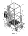
- Figure 2 shows a perspective view of the elevator of the previous figure with the loading moving device arranged on its support and guide structure prior to the coupling thereof to the frame.
- Figure 3 shows a side elevational view of the elevator shown in the previous figure.
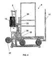
- Figure 4 shows a side elevational view of the elevator with the moving device or trolley coupled to the frame.
- Figure 5 shows a plan view of a detail of the elevator in which the two positions (A and B) of the second frame with horizontal movement with respect to the first frame for unloading on the floor can be seen.
- Figure 6 shows a perspective view of an elevator without the loading moving device or trolley in which a horizontal piston and guide coupling system can be observed.
- the load elevator for construction jobs proposed by the present application is formed by two basic assemblies, a base structure 3, 24 formed by a first frame 11 associated to a drive unit 12, a guide mast 2 and a support base, and a second structure coupled to the frame of the first structure formed by the loading moving device or trolley 4, which can be interchanged and provides free movements on the horizontal plane of the floor until it is coupled to the frame 11, 31 and 24.
- the base 1 of the base structure 3 of the device is formed by two longitudinal bars 5-5' arranged in parallel and spaced from one another by two crosspieces 6 and 7.
- the bars 5-5' also incorporate on their surface respective guides 9-9' which facilitate positioning the trolley 4 on said base, transversely immobilizing it.
- the guide mast 2 projects perpendicularly from the middle area of the cross-beams 6 and 7, which mast has a light-weight and resistant modular lattice structure allowing the longitudinal coupling of a plurality of modules so as to adapt it to the required height, said mast incorporating a longitudinal rack 10 allowing the movement of the first frame 11 thereof.
- the first frame 11 has a planar rectangular structure parallel to the guide mast 2 on which a drive unit 12 is installed, integral thereto, incorporating the different drive and safety elements common to this type of devices for their movement along the mast 2 through the rack 10, which engages with the gear wheels or gears arranged in the running gear of the first frame.
- the frame 11 On the side opposite to the one incorporating the drive unit 12, the frame 11 has an securing or coupling system formed by four bolts 13 distributed in its four corners for coupling the loading moving trolleys 4 by means of through holes 22 arranged on the inner side of the trolley 4 to the frame 11 which can move vertically.
- the distance between said bolts can be modified according to the width of the trolley 4 to be coupled to the frame 11, 31.
- Said anchoring system has an additional safety device for preventing the accidental movement of the moving device.
- Said safety device is formed by a solid longitudinal element 34 arranged transversely between at least two preferably through holes 35 located on the frame 11 and at least one through groove 36 preferably located on a vertical bar 20 joined to the trussing of the moving device 4, said groove being located between the two through holes 35 of the frame.
- the elevator can also incorporate a second frame 31 coupled to the first frame 11 integral with the drive unit 12, said second frame 31 in this case incorporating the coupling means for coupling it to the loading moving device and horizontal movement means 32 with respect to the first frame 11.
- Said horizontal movement means can be manually actuated in the case of using a worm screw 32 manually actuated through the actuator 33, or automatically actuated by means of using at least one linear moving device (not shown).
- the elevator can introduce the loading moving device on the upper floor for the subsequent detachment thereof and horizontal transfer of the moving device throughout the floor, and vice versa.
- Figure 6 shows an alternative coupling system between the frame 11, 31 and a set of loading moving devices or trolleys 4.
- the base structure 24 of the elevator incorporates a first frame 11, associated to a drive unit 12, a guide mast 2 and support base incorporating the coupling system.
- Said coupling system is carried out by means of guides 25-25' forming the base of the elevator and on which there are arranged cones 26-26' defining the coupling position of the trolley 4.
- an X-shaped structure 27 supporting at its intersection a pair of pistons 28, 28' which are actuated by the longitudinal movement of an actuator 29.
- the loading moving device or trolleys 4 for transporting the scaffolds are formed from a loading platform 14, provided at the bottom part with at least one running gear, with its respective wheels 15, spaced a length that is suitable for the distance between the guides 9, 9' present in the support base 1, to allow their positioning thereupon.
- the rear running gear 16 of said transport trolley 4 incorporates an arm 17 which can be lowered and is integral therewith and allows manually controlling the horizontal movement of said trolley 4 by means of a handgrip 18.
- the platform 14 incorporates at its upper part a metallic trussing 19 forming the safety area for loading the materials, the side of which that is parallel to the raising mast 2 incorporates an element for the coupling to the moving device 3, formed by a vertical bar 20 joined to the metallic trussing 19 in the middle area thereof, and from which respective pairs of flanges 21 project perpendicularly, which flanges are vertically spaced from one another by the same distance existing vertically between the raising hitches 13, each of the mentioned flanges 21 incorporating a through hole 22 with suitable sizes for the male coupling parts 23 of the raising hitches 13.
Landscapes
- Engineering & Computer Science (AREA)
- Transportation (AREA)
- Structural Engineering (AREA)
- Civil Engineering (AREA)
- Life Sciences & Earth Sciences (AREA)
- Geology (AREA)
- Mechanical Engineering (AREA)
- Types And Forms Of Lifts (AREA)
Applications Claiming Priority (1)
| Application Number | Priority Date | Filing Date | Title |
|---|---|---|---|
| PCT/ES2005/000282 WO2006122992A2 (es) | 2005-05-19 | 2005-05-19 | Elevador |
Publications (1)
| Publication Number | Publication Date |
|---|---|
| EP1889807A2 true EP1889807A2 (de) | 2008-02-20 |
Family
ID=37431616
Family Applications (1)
| Application Number | Title | Priority Date | Filing Date |
|---|---|---|---|
| EP05750578A Withdrawn EP1889807A2 (de) | 2005-05-19 | 2005-05-19 | Aufzug |
Country Status (2)
| Country | Link |
|---|---|
| EP (1) | EP1889807A2 (de) |
| WO (1) | WO2006122992A2 (de) |
Family Cites Families (6)
| Publication number | Priority date | Publication date | Assignee | Title |
|---|---|---|---|---|
| FR2268745A1 (en) * | 1974-04-25 | 1975-11-21 | Meunier Michel | Mechanical lifting platform - has guardrails on three sides and fourth open for truck entry and exit |
| JPH0733358A (ja) * | 1993-07-20 | 1995-02-03 | Techman:Kk | 荷物用エレベータの注油装置 |
| JPH11236191A (ja) * | 1998-02-23 | 1999-08-31 | Kuroi Electric Co Ltd | 自動昇降物干方式並びにその方式における昇降ポール及び搬送カート |
| JP2897011B1 (ja) * | 1998-04-22 | 1999-05-31 | 株式会社をくだ屋技研 | リフトトラック |
| JP2004099312A (ja) * | 2002-09-09 | 2004-04-02 | Choju Kametani | 360度回転方式による荷台が転換して台車となる昇降機 |
| AT500228B1 (de) * | 2003-05-20 | 2007-07-15 | Tgw Transportgeraete Gmbh | Teleskopschubarm, insbesondere für eine lastaufnahmevorrichtung |
-
2005
- 2005-05-19 EP EP05750578A patent/EP1889807A2/de not_active Withdrawn
- 2005-05-19 WO PCT/ES2005/000282 patent/WO2006122992A2/es not_active Ceased
Non-Patent Citations (1)
| Title |
|---|
| See references of WO2006122992A3 * |
Also Published As
| Publication number | Publication date |
|---|---|
| WO2006122992A3 (es) | 2007-09-20 |
| WO2006122992A2 (es) | 2006-11-23 |
Similar Documents
| Publication | Publication Date | Title |
|---|---|---|
| US8306706B2 (en) | Storage container loading/unloading and transporting apparatus | |
| KR100940889B1 (ko) | 스토리지 컨테이너의 로딩과 언로딩 및 운송장치 | |
| KR101506634B1 (ko) | 정밀설비물류용 리프트크레인 | |
| US5159993A (en) | Self-raising work platform assembly | |
| KR100956177B1 (ko) | 고소작업대 | |
| KR20160127802A (ko) | 골조 부재를 위한 컨테이너 | |
| US4897011A (en) | Mechanical lift device | |
| US20100230559A1 (en) | Gantry device for use in the assembly or maintenance of heavy parts of a travelling device | |
| KR100703766B1 (ko) | 리프트용 독립 지주식 가이드레일 | |
| EP1889807A2 (de) | Aufzug | |
| CN116568627A (zh) | 用于提升竖立模板的点加载式提升叉 | |
| EP1388519A2 (de) | Gabelstapler und Lastumschlagsmethode | |
| CN108086661B (zh) | 运输平台系统及其应用施工方法 | |
| RU2405733C2 (ru) | Подъемник | |
| US5027921A (en) | Method and device for transporting and distributing materials and/or equipment around the periphery of a building | |
| JPS61146972A (ja) | トラツク、バス等重量物の昇降兼立体駐車装置 | |
| KR102255701B1 (ko) | 테이블 폼 운반용 대차 | |
| KR101039829B1 (ko) | 핸드 건 거치대 | |
| JP7627731B1 (ja) | 重量物運搬装置 | |
| CZ289665B6 (cs) | Leąení | |
| JP2003095407A (ja) | テーブル上の台車により物品を搬入搬出する方法 | |
| KR100458096B1 (ko) | 이동형 간이 리프트 장치 | |
| JP2004143677A (ja) | 建築機材の搬出入装置 | |
| US5575356A (en) | Lift | |
| CN205709690U (zh) | 一种托架升运车 |
Legal Events
| Date | Code | Title | Description |
|---|---|---|---|
| PUAI | Public reference made under article 153(3) epc to a published international application that has entered the european phase |
Free format text: ORIGINAL CODE: 0009012 |
|
| 17P | Request for examination filed |
Effective date: 20071218 |
|
| AK | Designated contracting states |
Kind code of ref document: A2 Designated state(s): AT BE BG CH CY CZ DE DK EE ES FI FR GB GR HU IE IS IT LI LT LU MC NL PL PT RO SE SI SK TR |
|
| AX | Request for extension of the european patent |
Extension state: AL BA HR LV MK YU |
|
| RBV | Designated contracting states (corrected) |
Designated state(s): AT BE BG CH CY CZ DE DK EE ES FI FR GB GR HU IE IS IT LI LT LU MC NL PL PT RO SE SI SK TR |
|
| RAX | Requested extension states of the european patent have changed |
Extension state: YU Payment date: 20071218 Extension state: HR Payment date: 20071218 |
|
| STAA | Information on the status of an ep patent application or granted ep patent |
Free format text: STATUS: THE APPLICATION IS DEEMED TO BE WITHDRAWN |
|
| 18D | Application deemed to be withdrawn |
Effective date: 20111201 |