EP1889808B1 - Kranarm mit einer Befestigungsvorrichtung für Arbeitsgeräte - Google Patents
Kranarm mit einer Befestigungsvorrichtung für Arbeitsgeräte Download PDFInfo
- Publication number
- EP1889808B1 EP1889808B1 EP06007069A EP06007069A EP1889808B1 EP 1889808 B1 EP1889808 B1 EP 1889808B1 EP 06007069 A EP06007069 A EP 06007069A EP 06007069 A EP06007069 A EP 06007069A EP 1889808 B1 EP1889808 B1 EP 1889808B1
- Authority
- EP
- European Patent Office
- Prior art keywords
- crane arm
- hose lines
- connections
- rotary joint
- working implement
- Prior art date
- Legal status (The legal status is an assumption and is not a legal conclusion. Google has not performed a legal analysis and makes no representation as to the accuracy of the status listed.)
- Expired - Lifetime
Links
Images


Classifications
-
- B—PERFORMING OPERATIONS; TRANSPORTING
- B66—HOISTING; LIFTING; HAULING
- B66C—CRANES; LOAD-ENGAGING ELEMENTS OR DEVICES FOR CRANES, CAPSTANS, WINCHES, OR TACKLES
- B66C1/00—Load-engaging elements or devices attached to lifting or lowering gear of cranes or adapted for connection therewith for transmitting lifting forces to articles or groups of articles
- B66C1/10—Load-engaging elements or devices attached to lifting or lowering gear of cranes or adapted for connection therewith for transmitting lifting forces to articles or groups of articles by mechanical means
- B66C1/22—Rigid members, e.g. L-shaped members, with parts engaging the under surface of the loads; Crane hooks
- B66C1/28—Duplicate, e.g. pivoted, members engaging the loads from two sides
-
- B—PERFORMING OPERATIONS; TRANSPORTING
- B66—HOISTING; LIFTING; HAULING
- B66C—CRANES; LOAD-ENGAGING ELEMENTS OR DEVICES FOR CRANES, CAPSTANS, WINCHES, OR TACKLES
- B66C3/00—Load-engaging elements or devices attached to lifting or lowering gear of cranes or adapted for connection therewith and intended primarily for transmitting lifting forces to loose materials; Grabs
- B66C3/005—Grab supports, e.g. articulations; Oscillation dampers; Orientation
Definitions
- the present invention relates to crane arm with a mounting device for implements, wherein the fastening device along a vertical axis spaced pivot joints with a crankshaft-side pivot and a work equipment-side universal joint in the manner of a universal joint, the axes of rotation are arranged perpendicular to each other, from the crane arm hose lines to terminals at one between Working device and implement side rotors arranged rotator lead and wherein the crankshaft-side pivot along its axis of rotation has two spaced pivot bearing and run the hose grinding from the crane arm to the connections between the two pivot bearings.
- crane arms with, for example, a mounted gripper as implement find application in numerous fields.
- such crane arms which are usually telescopically extendable, used on motor vehicles for loading a cargo area with cargo in mobile use.
- these are bulky loads such as logs or pipes.
- the rotator and the implement are usually operated by a hydraulic device. Therefore, lead from the crane arm to the rotator hydraulic hoses, while the actual control unit, the hydraulic reservoir and hydraulic pumps, etc., for example, at the other end of the crane arm, from where the control is carried out by a user
- Object of the present invention is that the connections for the crane arm on the facing side of the fastening device are arranged and the hose lines in the direction of the axis of rotation of the implement side rotary joint offset pass by this rotary joint.
- the connections for the hose lines are arranged on the side of the fastening device facing the crane arm.
- the hose lines are shielded from external influences and protected, for example, that the hose lines to hang on a tree or branch or injured on a sharp object.
- the fastening device is rotatably mounted about the axis of rotation of the crankshaft-side joint by an angle ⁇ , at usually the injected by the fastening device and the crane arm angle a is not more than 180 °, so that the fastening device always assigns the crane arm the same page. Passing the hoses on the crane arm side minimizes the risk of external damage.
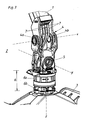
- the Fig. 1 shows a crane arm 1 with a fastening device 2 for a working device 3, which is formed in the present case of a gripper in the open position.
- the fastening device 2 has along the vertical axis z spaced hinges 4, 5 with a crankshaft-side pivot 4 and a working device-side pivot. 5 in the manner of a universal joint.
- the axes of rotation x, y of the rotary joints 4, 5 are arranged perpendicular to each other and perpendicular to the vertical axis z and thus form a Cartesian coordinate system.
- From crane arm 1 lead hoses 7 (see also Fig. 3 ) to terminals 8 at a disposed between the gripper 3 and the implement side rotary joint 5 rotator 6.
- the terminals 8 are directed approximately horizontally from the vertical axis z.
- the crane crane-side rotary joint 4 along its axis of rotation x is equipped with two pivot bearings 4a, 4b, wherein the hose lines 7 between these two pivot bearings 4a, 4b protrude or extend.
- the Fig. 2 with the detail view in Fig. 4 illustrates how the hose lines 7 extend to the terminals 8.
- the terminals 8 may be formed for example as bores, sockets or sleeves.
- the terminals 8 bolt-like projections with a bolt thread on which the tubes 7 are screwed with sleeve attachments having a female thread. Therefore, the actual terminals 8 are hidden in the representation of the sleeve attachments.
- Other, preferably releasable attachment mechanisms are provided within the scope of the invention.
- the terminals 8 are arranged in the embodiment shown outside the pivot bearing of the rotary joint 5.
- the hose lines 7 can lead out of the interior of the crane arm 1, be passed between the pivot bearings 4a, 4b and are guided to the crane arm 1 facing side 1a of the fastening device 2, where the terminals. 8 for the hose lines 7 are located.
- the included angle ⁇ between crane arm 1 and fastening device 2 is usually less than 180 °, so that the passage of the hose lines 7 of the fastening device 2 on the crane arm 1 facing side 1 a shows a protective effect for the tubes 7.
- the rotator 6, which is in the Fig. 4 is shown more clearly, allows rotation of the connected implement 3 along the vertical axis z.
- the working device 3 facing part 6b of the rotating device 6 is rotatable relative to the fastening device.
- the upper, the crane arm 1 facing part 6a, where the terminals 8 are located, remains at a rotation (of 6b) to z in the starting position.
- the actual configuration of the rotator 6 can be done in a conventional manner.
Landscapes
- Engineering & Computer Science (AREA)
- Mechanical Engineering (AREA)
- Jib Cranes (AREA)
- Forklifts And Lifting Vehicles (AREA)
- Load-Engaging Elements For Cranes (AREA)
- Joints Allowing Movement (AREA)
Description
- Die vorliegende Erfindung betrifft Kranarm mit einer Befestigungsvorrichtung für Arbeitsgeräte, wobei die Befestigungsvorrichtung entlang einer vertikalen Achse beabstandete Drehgelenke mit einem kranarmseitigen Drehgelenk und einem arbeitsgeräteseitigen Drehgelenk nach Art eines Kardangelenks aufweist, deren Drehachsen senkrecht zueinander angeordnet sind, wobei vom Kranarm Schlauchleitungen zu Anschlüssen an einem zwischen Arbeitsgerät und arbeitsgeräteseitigem Drehgelenk angeordneten Rotator führen und wobei das kranarmseitige Drehgelenk entlang seiner Drehachse zwei beabstandete Drehlager aufweist und die Schlauchleifungen vom Kranarm zu den Anschlüssen zwischen den beiden Drehlagern verlaufen.
- Gattungsgemäße Kranarme mit zum Beispiel einem angebrachten Greifer als Arbeitsgerät finden in zahlreichen Gebieten Anwendung. Beispielsweise werden solche Kranarme, die in der Regel teleskopartig ausfahrbar sind, auf Kraftfahrzeugen zum Beladen einer Ladefläche mit Ladegut im mobilen Einsatz verwendet. Typischerweise handelt es sich dabei um sperriges Ladegut wie Baumstämme oder Rohrleitungen. Auch der stationäre Einsatz solcher Kranarme in Verschrottungsanlagen, in Müllverarbeitungsanlagen oder in der Bauindustrie kann häufig beobachtet werden. Der Rotator und das Arbeitsgerät werden meistens über eine Hydraulikeinrichtung betrieben. Deshalb führen vom Kranarm zum Rotator Hydraulikschläuche, während sich die eigentliche Steuerungseinheit, das Hydraulikreservoir und Hydraulikpumpen etc. beispielsweise am anderen Ende des Kranarms befinden, von wo aus auch die Steuerung durch einen Benutzer erfolgt
- Beim Stand der Technik gemäß
US 2005/0017528 ist vorteilhaft, dass die Schlauchleitungen, die vom Kranarm zur Rotationseinrichtung führen, nicht leicht von außen beschädigt werden können, beispielsweise durch Äste, Ladegut oder anderes Werkzeug, wodurch es zum Auslaufen von Hydraulikflüssigkeit kommen kann. Ein solches Auslaufen von Hydraulikflüssigkeit beeinträchtigt die Funktion des Kranarms und es kann zu Gefahrenmomenten kommen. - Aufgabe der vorliegenden Erfindung ist es, die Anschlüsse für die an der dem Kranarm zugewandten Seite der Befestigungsvorrichtung angeordnet sind und die Schlauchleitungen in Richtung der Drehachse des arbeitsgeräteseitigen Drehgelenks versetzt an diesem Drehgelenk vorbeilaufen.
- Erfindungsgemäß wird dies durch einen Kranarm der eingangs genannten Gattung erreicht, unter Beibehaltung des erwähnten Vorteiles das Kardangelenk insgesamt möglichst stabil auszubilden und die Anschlüsse für die Schlauchleitungen gut von außen zugänglich zu machen.
- Als besonders vorteilhaft hat es sich erwiesen, dass die Anschlüsse für die Schlauchleitungen an der dem Kranarm zugewandten Seite der Befestigungsvorrichtung angeordnet sind. Durch das Anordnen der Anschlüsse für die Schlauchleitungen an der dem Kranarm zugewandten Seite der Befestigungsvorrichtung sind die Schlauchleitungen vor externen Einflüssen abgeschirmt und beispielsweise davor geschützt, dass die Schlauchleitungen an einem Baum bzw. Ast hängen bleiben oder an einem scharfen Gegenstand verletzt werden. In der Arbeitsstellung ist die Befestigungsvorrichtung um die Drehachse des kranarmseitigen Gelenks um einen Winkel α drehbar gelagert, bei in der Regel der von der Befestigungsvorrichtung und dem Kranarm eingeschossene Winkel a nicht mehr als 180° beträgt, sodass die Befestigungsvorrichtung dem Kranarm stets dieselbe Seite zuweist. Das Vorbeiführen der Schlauchleitungen auf der dem Kranarm zugewandten Seite minimiert das Risiko durch externe Beschädigung erheblich.
- Weitere Vorteile sowie Details der Erfindung werden anhand der vorliegenden Figuren und Figurenbeschreibungen mittels eines Ausführungsbeispieles näher erläutert. Dabei zeigt
- Fig. 1
- schematisch einen erfindungsgemäßen Kranarm im Schrägriss,
- Fig. 2
- den Kranarm von
Fig. 1 im Schrägriss aus einer andern Perspektive und - Fig. 3 und 4
- Detailansichten der Befestigungsvorrichtung gemäß
Fig. 1 bzw.Fig. 2 . - Die
Fig. 1 zeigt einen Kranarm 1 mit einer Befestigungsvorrichtung 2 für ein Arbeitsgerät 3, das im vorliegenden Fall von einem Greifer in geöffneter Stellung gebildet wird. Die Befestigungsvorrichtung 2 weist entlang der vertikalen Achse z beabstandete Drehgelenke 4, 5 mit einem kranarmseitigen Drehgelenk 4 und einem arbeitsgeräteseitigen Drehgelenk 5 nach Art eines Kardangelenks auf. Die Drehachsen x, y der Drehgelenke 4, 5 sind senkrecht zueinander sowie senkrecht zur vertikalen Achse z angeordnet und bilden somit ein kartesisches Koordinatensystem. Vom Kranarm 1 führen Schlauchleitungen 7 (siehe auchFig. 3 ) zu Anschlüssen 8 an einem zwischen dem Greifer 3 und dem arbeitsgeräteseitigen Drehgelenk 5 angeordneten Rotator 6. Die Anschlüsse 8 sind etwa horizontal von der vertikalen Achse z weggerichtet. Im vorliegenden Fall weist jeder einzelne Anschluss in Richtung der Drehachse y des arbeitsgeräteseitigen Drehgelenks 5. Wie deutlich anhand derFig. 3 erkennbar ist, ist das kranarmseitige Drehgelenk 4 entlang seiner Drehachse x mit zwei Drehlagern 4a, 4b ausgestattet, wobei die Schlauchleitungen 7 zwischen diesen beiden Drehlagern 4a, 4b durchragen bzw. verlaufen. - Die
Fig. 2 mit der Detailansicht inFig. 4 verdeutlicht, wie die Schlauchleitungen 7 zu den Anschlüssen 8 verlaufen. Die Anschlüsse 8 können beispielsweise als Bohrungen, Buchsen oder Hülsen ausgebildet sein. Im vorliegenden Fall sind die Anschlüsse 8 bolzenartige Vorsprünge mit einem Bolzengewinde, auf die die Schläuche 7 mit Hülsenaufsätzen, die ein Muttergewinde aufweisen, aufgeschraubt sind. Daher sind die eigentlichen Anschlüsse 8 in der Darstellung von den Hülsenaufsätzen verdeckt. Auch andere, vorzugsweise lösbare Befestigungsmechanismen sind im Rahmen der Erfindung vorgesehen. Die Anschlüsse 8 sind im gezeigten Ausführungsbeispiel außerhalb der Drehlager des Drehgelenks 5 angeordnet. - Im bevorzugten Fall (wie auch im dargestellten Ausführungsbeispiel) können die Schlauchleitungen 7 aus dem Inneren des Kranarms 1 herausführen, zwischen den Drehlagern 4a, 4b hindurchgeführt werden und an die dem Kranarm 1 zugewandte Seite 1a der Befestigungsvorrichtung 2 geführt werden, wo sich die Anschlüsse 8 für die Schlauchleitungen 7 befinden. In Arbeitsstellung ist der eingeschlossene Winkel α zwischen Kranarm 1 und Befestigungsvorrichtung 2 in der Regel geringer als 180°, sodass das Vorbeiführen der Schlauchleitungen 7 der Befestigungsvorrichtung 2 an der dem Kranarm 1 zugewandten Seite 1 a einen schützenden Effekt für die Schläuche 7 zeigt. Der Rotator 6, der in der
Fig. 4 noch deutlicher dargestellt ist, ermöglicht eine Rotation des angeschlossenen Arbeitsgerätes 3 entlang der vertikalen Achse z. Dabei ist der dem Arbeitsgerät 3 zugewandte Teil 6b der Rotationseinrichtung 6 relativ zur Befestigungsvorrichtung drehbar. Der obere, dem Kranarm 1 zugewandte Teil 6a, an dem sich auch die Anschlüsse 8 befinden, bleibt bei einer Rotation (von 6b) um z in Ausgangslage. Die eigentliche Ausgestaltung des Rotators 6 kann in an sich bekannter Weise erfolgen.
Claims (1)
- Kranarm mit einer Befestigungsvorrichtung für Arbeitsgeräte, wobei die Befestigungsvorrichtung entlang einer vertikalen Achse beabstandete Drehgelenke mit einem kranarmseitigen Drehgelenk und einem arbeitsgeräteseitigen Drehgelenk nach Art eines Kardangelenks aufweist, deren Drehachsen senkrecht zueinander angeordnet sind, wobei vom Kranarm Schlauchleitungen zu Anschlüssen an einem zwischen Arbeitsgerät und arbeitsgeräteseitigem Drehgelenk angeordneten Rotator führen und wobei das kranarmseitige Drehgelenk entlang seiner Drehachse zwei beabstandete Drehlager aufweist und die Schlauchleitungen vom Kranarm zu den Anschlüssen zwischen den beiden Drehlagern verlaufen, dadurch gekennzeichnet, dass die Anschlüsse (8) für die Schlauchleitungen (7) an der dem Kranarm (1) zugewandten Seite (1a) der Befestigungsvorrichtung (2) angeordnet sind und die Schlauchleitungen (7) in Richtung der Drehachse des arbeitsgeräteseitigen Drehgelenks versetzt an diesem Drehgelenk vorbeilaufen.
Priority Applications (8)
| Application Number | Priority Date | Filing Date | Title |
|---|---|---|---|
| SI200630478T SI1889808T1 (sl) | 2006-04-03 | 2006-04-03 | Roka Ĺľerjava s pritrdilno napravo za delovno orodje |
| EP06007069A EP1889808B1 (de) | 2006-04-03 | 2006-04-03 | Kranarm mit einer Befestigungsvorrichtung für Arbeitsgeräte |
| ES06007069T ES2330770T3 (es) | 2006-04-03 | 2006-04-03 | Pescante de una grua con un dispositivo de fijacion para instrumentos de trabajo. |
| DE502006004800T DE502006004800D1 (de) | 2006-04-03 | 2006-04-03 | Kranarm mit einer Befestigungsvorrichtung für Arbeitsgeräte |
| DK06007069T DK1889808T3 (da) | 2006-04-03 | 2006-04-03 | Kranarm med en fastgörelsesindretning til arbejdsredskaber |
| AT06007069T ATE442339T1 (de) | 2006-04-03 | 2006-04-03 | Kranarm mit einer befestigungsvorrichtung für arbeitsgeräte |
| KR1020070031696A KR101024512B1 (ko) | 2006-04-03 | 2007-03-30 | 작업 수행부용 고정 장치를 가지는 크레인 아암 |
| RU2007112098/11A RU2362725C2 (ru) | 2006-04-03 | 2007-04-02 | Стрела крана с устройством крепления рабочих органов |
Applications Claiming Priority (1)
| Application Number | Priority Date | Filing Date | Title |
|---|---|---|---|
| EP06007069A EP1889808B1 (de) | 2006-04-03 | 2006-04-03 | Kranarm mit einer Befestigungsvorrichtung für Arbeitsgeräte |
Publications (2)
| Publication Number | Publication Date |
|---|---|
| EP1889808A1 EP1889808A1 (de) | 2008-02-20 |
| EP1889808B1 true EP1889808B1 (de) | 2009-09-09 |
Family
ID=36930315
Family Applications (1)
| Application Number | Title | Priority Date | Filing Date |
|---|---|---|---|
| EP06007069A Expired - Lifetime EP1889808B1 (de) | 2006-04-03 | 2006-04-03 | Kranarm mit einer Befestigungsvorrichtung für Arbeitsgeräte |
Country Status (8)
| Country | Link |
|---|---|
| EP (1) | EP1889808B1 (de) |
| KR (1) | KR101024512B1 (de) |
| AT (1) | ATE442339T1 (de) |
| DE (1) | DE502006004800D1 (de) |
| DK (1) | DK1889808T3 (de) |
| ES (1) | ES2330770T3 (de) |
| RU (1) | RU2362725C2 (de) |
| SI (1) | SI1889808T1 (de) |
Cited By (4)
| Publication number | Priority date | Publication date | Assignee | Title |
|---|---|---|---|---|
| EP2460758A1 (de) | 2010-12-02 | 2012-06-06 | EPSILON Kran GmbH. | Hydraulischer Rotationsantrieb |
| EP2570379A1 (de) | 2011-09-15 | 2013-03-20 | EPSILON Kran GmbH. | Drehgelenkanordnung |
| EP2789565A1 (de) | 2013-04-08 | 2014-10-15 | Penz crane GmbH | Befestigungsvorrichtung für ein drehbar an einem Kran gelagertes Werkzeug |
| EP3165494A1 (de) | 2015-11-05 | 2017-05-10 | Mesera Cranes Finland Oy | Schlauchschutz für einen gelenkkran und gelenkarmanordnung eines gelenkkrans |
Families Citing this family (16)
| Publication number | Priority date | Publication date | Assignee | Title |
|---|---|---|---|---|
| SE535793C2 (sv) * | 2010-04-13 | 2012-12-18 | Indexator Group Ab | Anordning för styrning av slangar och/eller kablar |
| SE537511C2 (sv) * | 2012-11-20 | 2015-05-26 | Komatsu Forest Ab | Vägningssystem för last som hanteras med en lyftapparat, ochlastavkännande ledbar förbindning |
| SI24257B (sl) | 2012-12-12 | 2017-07-31 | Tajfun Liv, Proizvodnja In Razvoj D.O.O. | Pritrdilna enota vrtljivega prijemala ali podobnega delovnega orodja na roki hidravličnega dvigala |
| SE1300134A1 (sv) * | 2013-02-20 | 2014-08-19 | Cranab Ab | Kranarm som bär en rotator |
| US10100487B2 (en) * | 2013-07-10 | 2018-10-16 | Tigercat Industries Inc. | Hydraulic assembly and logging equipment using same |
| EP2974990B1 (de) * | 2014-07-18 | 2017-02-15 | Binderberger Mashinenbau GmbH | Kreuzgelenkkupplung |
| FI126839B (fi) * | 2016-05-03 | 2017-06-15 | Ponsse Oyj | Järjestely työkoneen nostolaitteessa, työkoneen nostolaite ja työkone |
| GB2550891A (en) * | 2016-05-27 | 2017-12-06 | Ultra Electronics Ltd | Mechanical link |
| SE541658C2 (sv) * | 2016-06-16 | 2019-11-19 | Komatsu Forest Ab | Anordning för slangföring vid ett kranburet arbetsredskap |
| SE541642C2 (en) * | 2016-08-26 | 2019-11-19 | Indexator Rotator Sys Ab | Rotator arrangement with hydraulic coupling through rotor |
| SE541661C2 (en) * | 2017-03-06 | 2019-11-19 | Indexator Rotator Sys Ab | Rotator arrangement with an angle meter |
| IT201700091689A1 (it) * | 2017-08-08 | 2019-02-08 | Negrini Srl | Testa orientabile per benne |
| EP3640514B1 (de) * | 2018-10-19 | 2023-06-07 | Deere & Company | Hydraulische verbindung und hydraulische auslegerkrananordnung mit einer hydraulischen verbindung |
| FR3123909B1 (fr) * | 2021-06-14 | 2023-06-09 | Carrosserie Vincent Et Fils | Grue embarquée de pose de poteaux |
| AU2021232719B2 (en) * | 2021-09-15 | 2023-07-06 | Komatsu Forest Ab | Internal line routing for working machines having boom arms |
| AT527926B1 (de) | 2024-05-14 | 2025-08-15 | Lechner Konrad | Pendelgelenk zur befestigung hydraulisch betätigter arbeitsgeräte |
Family Cites Families (5)
| Publication number | Priority date | Publication date | Assignee | Title |
|---|---|---|---|---|
| DE2262942C3 (de) * | 1972-12-22 | 1978-11-02 | Massey-Ferguson Services N.V., Curacao (Niederlaendische Antillen) | Pendelbremse für hydraulische Greifer |
| FR2411275A1 (fr) * | 1977-12-06 | 1979-07-06 | Poclain Sa | Dispositif de montage a rotation d'un organe pivotant d'outil a fluide sous pression, tel qu'une benne preneuse |
| RU2169673C2 (ru) * | 1999-04-14 | 2001-06-27 | ЗАО "НК Уралтерминалмаш" | Кран-манипулятор лесовозный |
| SE520498E8 (sv) * | 2001-11-26 | 2015-10-20 | Komatsu Forest Ab | Anordning för upphängning av ett vridbart arbetsredskap |
| RU2240973C2 (ru) * | 2002-05-23 | 2004-11-27 | Закрытое акционерное общество "Национальная компания Уралтерминалмаш" | Грузоподъёмная стрела крано-манипуляторной установки |
-
2006
- 2006-04-03 AT AT06007069T patent/ATE442339T1/de active
- 2006-04-03 DK DK06007069T patent/DK1889808T3/da active
- 2006-04-03 EP EP06007069A patent/EP1889808B1/de not_active Expired - Lifetime
- 2006-04-03 ES ES06007069T patent/ES2330770T3/es not_active Expired - Lifetime
- 2006-04-03 DE DE502006004800T patent/DE502006004800D1/de not_active Expired - Lifetime
- 2006-04-03 SI SI200630478T patent/SI1889808T1/sl unknown
-
2007
- 2007-03-30 KR KR1020070031696A patent/KR101024512B1/ko active Active
- 2007-04-02 RU RU2007112098/11A patent/RU2362725C2/ru active
Cited By (4)
| Publication number | Priority date | Publication date | Assignee | Title |
|---|---|---|---|---|
| EP2460758A1 (de) | 2010-12-02 | 2012-06-06 | EPSILON Kran GmbH. | Hydraulischer Rotationsantrieb |
| EP2570379A1 (de) | 2011-09-15 | 2013-03-20 | EPSILON Kran GmbH. | Drehgelenkanordnung |
| EP2789565A1 (de) | 2013-04-08 | 2014-10-15 | Penz crane GmbH | Befestigungsvorrichtung für ein drehbar an einem Kran gelagertes Werkzeug |
| EP3165494A1 (de) | 2015-11-05 | 2017-05-10 | Mesera Cranes Finland Oy | Schlauchschutz für einen gelenkkran und gelenkarmanordnung eines gelenkkrans |
Also Published As
| Publication number | Publication date |
|---|---|
| KR101024512B1 (ko) | 2011-03-31 |
| RU2007112098A (ru) | 2008-10-10 |
| RU2362725C2 (ru) | 2009-07-27 |
| DK1889808T3 (da) | 2009-12-07 |
| EP1889808A1 (de) | 2008-02-20 |
| KR20070099448A (ko) | 2007-10-09 |
| SI1889808T1 (sl) | 2010-01-29 |
| ES2330770T3 (es) | 2009-12-15 |
| ATE442339T1 (de) | 2009-09-15 |
| DE502006004800D1 (de) | 2009-10-22 |
Similar Documents
| Publication | Publication Date | Title |
|---|---|---|
| EP1889808B1 (de) | Kranarm mit einer Befestigungsvorrichtung für Arbeitsgeräte | |
| EP3122520A1 (de) | Roboterarm und montageset | |
| EP2743039B1 (de) | Roboterarm | |
| DE202017007033U1 (de) | Struktur einer Drehvorrichtung und eine entsprechende Drehvorrichtung sowie eine Forstmaschine | |
| DE202008006381U1 (de) | Schwenkverbinder für Absaugleitungen von Oberflächenbearbeitungswerkzeugen | |
| EP3875692A1 (de) | Schnellwechsler für eine baumaschine | |
| EP2460758A1 (de) | Hydraulischer Rotationsantrieb | |
| EP3730697B1 (de) | Adapter für ein schnellwechselsystem und schnellwechselsystem mit einem solchen adapter | |
| EP2631209B1 (de) | Kran | |
| DE202011004164U1 (de) | Schwenkmodul | |
| AT521315B1 (de) | Winkelstück und Hebevorrichtung | |
| AT13721U1 (de) | Befestigungsvorrichtung für ein drehbar an einem Kranarm gelagertes Werkzeug | |
| EP3388385B1 (de) | Rotationsantrieb | |
| EP2789565B1 (de) | Befestigungsvorrichtung für ein drehbar an einem Kran gelagertes Werkzeug | |
| DE10231724B4 (de) | Halteschelle | |
| DE102018127857B3 (de) | Roboterarm | |
| DE202006017189U1 (de) | Kranarm | |
| DE102005009252B4 (de) | Hydraulische Schwenkvorrichtung | |
| EP3124127B1 (de) | Hochdruckreinigungsgerät für die kleinteilreinigung | |
| DD201475A1 (de) | Arbeitsbuehne | |
| DE202009004125U1 (de) | Arretiervorrichtung | |
| DE9205757U1 (de) | Steckbolzenverbindung | |
| EP3009391A1 (de) | Kran | |
| DE19712621A1 (de) | Vorrichtung zum Ernten von Baumstämmen | |
| WO2021223801A1 (de) | Entriegelungshilfe |
Legal Events
| Date | Code | Title | Description |
|---|---|---|---|
| PUAI | Public reference made under article 153(3) epc to a published international application that has entered the european phase |
Free format text: ORIGINAL CODE: 0009012 |
|
| 17P | Request for examination filed |
Effective date: 20061122 |
|
| AK | Designated contracting states |
Kind code of ref document: A1 Designated state(s): AT BE BG CH CY CZ DE DK EE ES FI FR GB GR HU IE IS IT LI LT LU LV MC NL PL PT RO SE SI SK TR |
|
| AX | Request for extension of the european patent |
Extension state: AL BA HR MK YU |
|
| AKX | Designation fees paid |
Designated state(s): AT BE BG CH CY CZ DE DK EE ES FI FR GB GR HU IE IS IT LI LT LU LV MC NL PL PT RO SE SI SK TR |
|
| GRAP | Despatch of communication of intention to grant a patent |
Free format text: ORIGINAL CODE: EPIDOSNIGR1 |
|
| GRAS | Grant fee paid |
Free format text: ORIGINAL CODE: EPIDOSNIGR3 |
|
| GRAA | (expected) grant |
Free format text: ORIGINAL CODE: 0009210 |
|
| AK | Designated contracting states |
Kind code of ref document: B1 Designated state(s): AT BE BG CH CY CZ DE DK EE ES FI FR GB GR HU IE IS IT LI LT LU LV MC NL PL PT RO SE SI SK TR |
|
| REG | Reference to a national code |
Ref country code: GB Ref legal event code: FG4D Free format text: NOT ENGLISH |
|
| REG | Reference to a national code |
Ref country code: CH Ref legal event code: EP |
|
| REG | Reference to a national code |
Ref country code: IE Ref legal event code: FG4D |
|
| REF | Corresponds to: |
Ref document number: 502006004800 Country of ref document: DE Date of ref document: 20091022 Kind code of ref document: P |
|
| REG | Reference to a national code |
Ref country code: SE Ref legal event code: TRGR |
|
| REG | Reference to a national code |
Ref country code: DK Ref legal event code: T3 |
|
| REG | Reference to a national code |
Ref country code: ES Ref legal event code: FG2A Ref document number: 2330770 Country of ref document: ES Kind code of ref document: T3 |
|
| PG25 | Lapsed in a contracting state [announced via postgrant information from national office to epo] |
Ref country code: LT Free format text: LAPSE BECAUSE OF FAILURE TO SUBMIT A TRANSLATION OF THE DESCRIPTION OR TO PAY THE FEE WITHIN THE PRESCRIBED TIME-LIMIT Effective date: 20090909 |
|
| NLV1 | Nl: lapsed or annulled due to failure to fulfill the requirements of art. 29p and 29m of the patents act | ||
| LTIE | Lt: invalidation of european patent or patent extension |
Effective date: 20090909 |
|
| PG25 | Lapsed in a contracting state [announced via postgrant information from national office to epo] |
Ref country code: PL Free format text: LAPSE BECAUSE OF FAILURE TO SUBMIT A TRANSLATION OF THE DESCRIPTION OR TO PAY THE FEE WITHIN THE PRESCRIBED TIME-LIMIT Effective date: 20090909 Ref country code: NL Free format text: LAPSE BECAUSE OF FAILURE TO SUBMIT A TRANSLATION OF THE DESCRIPTION OR TO PAY THE FEE WITHIN THE PRESCRIBED TIME-LIMIT Effective date: 20090909 Ref country code: LV Free format text: LAPSE BECAUSE OF FAILURE TO SUBMIT A TRANSLATION OF THE DESCRIPTION OR TO PAY THE FEE WITHIN THE PRESCRIBED TIME-LIMIT Effective date: 20090909 |
|
| PG25 | Lapsed in a contracting state [announced via postgrant information from national office to epo] |
Ref country code: CY Free format text: LAPSE BECAUSE OF FAILURE TO SUBMIT A TRANSLATION OF THE DESCRIPTION OR TO PAY THE FEE WITHIN THE PRESCRIBED TIME-LIMIT Effective date: 20090909 |
|
| REG | Reference to a national code |
Ref country code: IE Ref legal event code: FD4D |
|
| PG25 | Lapsed in a contracting state [announced via postgrant information from national office to epo] |
Ref country code: RO Free format text: LAPSE BECAUSE OF FAILURE TO SUBMIT A TRANSLATION OF THE DESCRIPTION OR TO PAY THE FEE WITHIN THE PRESCRIBED TIME-LIMIT Effective date: 20090909 Ref country code: CZ Free format text: LAPSE BECAUSE OF FAILURE TO SUBMIT A TRANSLATION OF THE DESCRIPTION OR TO PAY THE FEE WITHIN THE PRESCRIBED TIME-LIMIT Effective date: 20090909 Ref country code: EE Free format text: LAPSE BECAUSE OF FAILURE TO SUBMIT A TRANSLATION OF THE DESCRIPTION OR TO PAY THE FEE WITHIN THE PRESCRIBED TIME-LIMIT Effective date: 20090909 Ref country code: PT Free format text: LAPSE BECAUSE OF FAILURE TO SUBMIT A TRANSLATION OF THE DESCRIPTION OR TO PAY THE FEE WITHIN THE PRESCRIBED TIME-LIMIT Effective date: 20100111 Ref country code: IS Free format text: LAPSE BECAUSE OF FAILURE TO SUBMIT A TRANSLATION OF THE DESCRIPTION OR TO PAY THE FEE WITHIN THE PRESCRIBED TIME-LIMIT Effective date: 20100109 Ref country code: IE Free format text: LAPSE BECAUSE OF FAILURE TO SUBMIT A TRANSLATION OF THE DESCRIPTION OR TO PAY THE FEE WITHIN THE PRESCRIBED TIME-LIMIT Effective date: 20090909 |
|
| PG25 | Lapsed in a contracting state [announced via postgrant information from national office to epo] |
Ref country code: SK Free format text: LAPSE BECAUSE OF FAILURE TO SUBMIT A TRANSLATION OF THE DESCRIPTION OR TO PAY THE FEE WITHIN THE PRESCRIBED TIME-LIMIT Effective date: 20090909 |
|
| PLBI | Opposition filed |
Free format text: ORIGINAL CODE: 0009260 |
|
| PLAX | Notice of opposition and request to file observation + time limit sent |
Free format text: ORIGINAL CODE: EPIDOSNOBS2 |
|
| 26 | Opposition filed |
Opponent name: CARGOTEC FINLAND OY Effective date: 20100607 |
|
| PG25 | Lapsed in a contracting state [announced via postgrant information from national office to epo] |
Ref country code: GR Free format text: LAPSE BECAUSE OF FAILURE TO SUBMIT A TRANSLATION OF THE DESCRIPTION OR TO PAY THE FEE WITHIN THE PRESCRIBED TIME-LIMIT Effective date: 20091210 |
|
| BERE | Be: lapsed |
Owner name: EPSILON KRAN GMBH Effective date: 20100430 |
|
| PLBB | Reply of patent proprietor to notice(s) of opposition received |
Free format text: ORIGINAL CODE: EPIDOSNOBS3 |
|
| PG25 | Lapsed in a contracting state [announced via postgrant information from national office to epo] |
Ref country code: MC Free format text: LAPSE BECAUSE OF NON-PAYMENT OF DUE FEES Effective date: 20100430 |
|
| REG | Reference to a national code |
Ref country code: CH Ref legal event code: PL |
|
| PG25 | Lapsed in a contracting state [announced via postgrant information from national office to epo] |
Ref country code: LI Free format text: LAPSE BECAUSE OF NON-PAYMENT OF DUE FEES Effective date: 20100430 Ref country code: CH Free format text: LAPSE BECAUSE OF NON-PAYMENT OF DUE FEES Effective date: 20100430 |
|
| PG25 | Lapsed in a contracting state [announced via postgrant information from national office to epo] |
Ref country code: BE Free format text: LAPSE BECAUSE OF NON-PAYMENT OF DUE FEES Effective date: 20100430 |
|
| PG25 | Lapsed in a contracting state [announced via postgrant information from national office to epo] |
Ref country code: BG Free format text: LAPSE BECAUSE OF FAILURE TO SUBMIT A TRANSLATION OF THE DESCRIPTION OR TO PAY THE FEE WITHIN THE PRESCRIBED TIME-LIMIT Effective date: 20090909 Ref country code: HU Free format text: LAPSE BECAUSE OF FAILURE TO SUBMIT A TRANSLATION OF THE DESCRIPTION OR TO PAY THE FEE WITHIN THE PRESCRIBED TIME-LIMIT Effective date: 20100310 Ref country code: LU Free format text: LAPSE BECAUSE OF NON-PAYMENT OF DUE FEES Effective date: 20100403 |
|
| PG25 | Lapsed in a contracting state [announced via postgrant information from national office to epo] |
Ref country code: TR Free format text: LAPSE BECAUSE OF FAILURE TO SUBMIT A TRANSLATION OF THE DESCRIPTION OR TO PAY THE FEE WITHIN THE PRESCRIBED TIME-LIMIT Effective date: 20090909 |
|
| REG | Reference to a national code |
Ref country code: DE Ref legal event code: R082 Ref document number: 502006004800 Country of ref document: DE Representative=s name: ISARPATENT GBR PATENT- UND RECHTSANWAELTE, DE Effective date: 20130620 Ref country code: DE Ref legal event code: R081 Ref document number: 502006004800 Country of ref document: DE Owner name: EPSILON KRAN GMBH., AT Free format text: FORMER OWNER: EPSILON KRAN GMBH, BERGHEIM, AT Effective date: 20130620 Ref country code: DE Ref legal event code: R082 Ref document number: 502006004800 Country of ref document: DE Representative=s name: ISARPATENT PATENTANWAELTE BEHNISCH, BARTH, CHA, DE Effective date: 20130620 Ref country code: DE Ref legal event code: R082 Ref document number: 502006004800 Country of ref document: DE Representative=s name: ISARPATENT - PATENTANWAELTE- UND RECHTSANWAELT, DE Effective date: 20130620 |
|
| PLAB | Opposition data, opponent's data or that of the opponent's representative modified |
Free format text: ORIGINAL CODE: 0009299OPPO |
|
| PLCK | Communication despatched that opposition was rejected |
Free format text: ORIGINAL CODE: EPIDOSNREJ1 |
|
| R26 | Opposition filed (corrected) |
Opponent name: CARGOTEC FINLAND OY Effective date: 20100607 |
|
| PLBN | Opposition rejected |
Free format text: ORIGINAL CODE: 0009273 |
|
| STAA | Information on the status of an ep patent application or granted ep patent |
Free format text: STATUS: OPPOSITION REJECTED |
|
| 27O | Opposition rejected |
Effective date: 20130115 |
|
| REG | Reference to a national code |
Ref country code: DE Ref legal event code: R100 Ref document number: 502006004800 Country of ref document: DE Effective date: 20130115 |
|
| PGFP | Annual fee paid to national office [announced via postgrant information from national office to epo] |
Ref country code: DK Payment date: 20150420 Year of fee payment: 10 |
|
| REG | Reference to a national code |
Ref country code: FR Ref legal event code: PLFP Year of fee payment: 11 |
|
| REG | Reference to a national code |
Ref country code: DK Ref legal event code: EBP Effective date: 20160430 |
|
| REG | Reference to a national code |
Ref country code: FR Ref legal event code: PLFP Year of fee payment: 12 |
|
| PG25 | Lapsed in a contracting state [announced via postgrant information from national office to epo] |
Ref country code: DK Free format text: LAPSE BECAUSE OF NON-PAYMENT OF DUE FEES Effective date: 20160430 |
|
| REG | Reference to a national code |
Ref country code: FR Ref legal event code: PLFP Year of fee payment: 13 |
|
| REG | Reference to a national code |
Ref country code: DE Ref legal event code: R008 Ref document number: 502006004800 Country of ref document: DE Ref country code: DE Ref legal event code: R039 Ref document number: 502006004800 Country of ref document: DE |
|
| REG | Reference to a national code |
Ref country code: DE Ref legal event code: R040 Ref document number: 502006004800 Country of ref document: DE |
|
| P01 | Opt-out of the competence of the unified patent court (upc) registered |
Effective date: 20230601 |
|
| PGFP | Annual fee paid to national office [announced via postgrant information from national office to epo] |
Ref country code: SE Payment date: 20250313 Year of fee payment: 20 |
|
| PGFP | Annual fee paid to national office [announced via postgrant information from national office to epo] |
Ref country code: SI Payment date: 20250313 Year of fee payment: 20 |
|
| PGFP | Annual fee paid to national office [announced via postgrant information from national office to epo] |
Ref country code: FI Payment date: 20250424 Year of fee payment: 20 |
|
| PGFP | Annual fee paid to national office [announced via postgrant information from national office to epo] |
Ref country code: DE Payment date: 20250428 Year of fee payment: 20 |
|
| PGFP | Annual fee paid to national office [announced via postgrant information from national office to epo] |
Ref country code: ES Payment date: 20250513 Year of fee payment: 20 Ref country code: GB Payment date: 20250422 Year of fee payment: 20 |
|
| PGFP | Annual fee paid to national office [announced via postgrant information from national office to epo] |
Ref country code: IT Payment date: 20250422 Year of fee payment: 20 |
|
| PGFP | Annual fee paid to national office [announced via postgrant information from national office to epo] |
Ref country code: FR Payment date: 20250424 Year of fee payment: 20 |
|
| PGFP | Annual fee paid to national office [announced via postgrant information from national office to epo] |
Ref country code: AT Payment date: 20250428 Year of fee payment: 20 |
|
| REG | Reference to a national code |
Ref country code: DE Ref legal event code: R071 Ref document number: 502006004800 Country of ref document: DE |
|
| REG | Reference to a national code |
Ref country code: GB Ref legal event code: PE20 Expiry date: 20260402 |
|
| REG | Reference to a national code |
Ref country code: ES Ref legal event code: FD2A Effective date: 20260424 |