EP1889809A2 - Levier pour dispositif de levage de couvercle - Google Patents
Levier pour dispositif de levage de couvercle Download PDFInfo
- Publication number
- EP1889809A2 EP1889809A2 EP20070011639 EP07011639A EP1889809A2 EP 1889809 A2 EP1889809 A2 EP 1889809A2 EP 20070011639 EP20070011639 EP 20070011639 EP 07011639 A EP07011639 A EP 07011639A EP 1889809 A2 EP1889809 A2 EP 1889809A2
- Authority
- EP
- European Patent Office
- Prior art keywords
- hook
- lifting arm
- projecting
- underside
- lift according
- Prior art date
- Legal status (The legal status is an assumption and is not a legal conclusion. Google has not performed a legal analysis and makes no representation as to the accuracy of the status listed.)
- Withdrawn
Links
Images



Classifications
-
- B—PERFORMING OPERATIONS; TRANSPORTING
- B66—HOISTING; LIFTING; HAULING
- B66F—HOISTING, LIFTING, HAULING OR PUSHING, NOT OTHERWISE PROVIDED FOR, e.g. DEVICES WHICH APPLY A LIFTING OR PUSHING FORCE DIRECTLY TO THE SURFACE OF A LOAD
- B66F19/00—Hoisting, lifting, hauling or pushing, not otherwise provided for
- B66F19/005—Lifting devices for manhole covers
Definitions
- the invention relates to a lifter for manhole cover with an upwardly directed lever and adjacent to the lower portion of a transverse axis arranged wheels and a forward projecting projecting rigid lifting arm on which a coupling hook can be mounted on the lid, the training such is that the lid is lifted by coupled hook by pivoting back of the hand lever.
- a lifter of this kind is in the EP 1 219 564 B1 specified.
- this known lift protrudes in the region of the underside of an upward hand lever in front of a supporting device with two lateral wheels before a lifting arm forward to which an attachable to the lid hook is adjustably mounted.
- the lifting arm has a rectilinear top surface on which the hook is supported by a cross member.
- the support device is provided laterally next to the lifting arm with side parts, which have rounded skids on their underside. It has been shown that this
- the invention has for its object to provide a lifter of the type mentioned above, which facilitates handling in many cases and improves the functionality.
- the lifting arm is provided on its upper side in use of the cover in its longitudinal direction with a concave shape and the hook is movably mounted on the lifting arm in the longitudinal direction and supported in the region of the concave shape.
- the hook can be easily attached to the lid and it is due to its automatic adjustment a safe function, whereby the use of force of the operator is minimized.
- the lifting arm is formed of two forwardly projecting, spaced apart arm parts, which are connected at least in their rear area facing the wheels by a transverse connecting element and between them a central portion of the Hook absorb, is mounted on the upwardly projecting portion with a transversely extending laterally projecting pin sliding or on rollers on the concave shape and in his on the Bottom over the underside of the lifting arm projecting portion carries a hook in the lid hook section.
- the hook in its lower, over the underside of the lifting arm projecting portion carries a transverse locking element with which the hook is locked against being pushed out of the lifting arm, the hook is held captive on the lifting arm in safe operation ,
- the laterally projecting pin is provided at its two laterally projecting ends with collar-like extensions which engage over the lifting arm on the outside, and that the distance between the peripheral edge of the extension on its underside and the top of the locking element is less than the width of the hook in the height direction.
- the handling and operation are also favored by the fact that the lifting arm is so far narrowed in its over the cross bar forward projecting area or in its rear area that the width in this area in the height direction is less than the distance on the hook between the peripheral edge of Extension on the underside and the top of the locking element or - in the presence of an inner guide part - is less than the distance between the lower edge and the upper side of the locking element.
- hooks can be easily exchanged for different purposes.
- a supporting device is formed with side parts which are provided at their forwardly projecting end portions on the bottom with a respective cover stop surface. Through the lid stop surface in combination with the hook, the lid is kept safe for transport when lifting.
- the measures are advantageous that connects to the cover stop surface in each case via a downward paragraph to the rear a Abstützkufe, the support of the lifter during pivoting back outside of the lid edge results.
- Fig. 1 shows a lifter for manhole cover 40 or the like.
- a supporting device with side wheels 30 upwardly directed hand lever 10
- the laterally projecting upwardly projecting portion 11.1 laterally protruding handles 12 carries.
- the wheels 30 are mounted in the lower region next to the hand lever 10 on a transverse axis 31, on which are located on the inside of the wheels additionally projecting forward side parts 7, which are connected to each other via a transverse section 8.
- a forward projecting lifting arm 1 is mounted, which consists of two lateral parts which form a space between them and are attached with its rear portion on the hand lever 10, which results in a stable transverse connecting element.
- the two lateral parts of the lifting arm 1 may be connected to each other, for example via a fixed bolt 6.
- the two lateral parts are narrowed in the height direction. Behind the fixed pin 6 is about in the area where the narrowed area merges into a widened area or behind the two lateral parts are provided with through holes into which a cross bar z.
- B. in the form of a ball locking pin 5 for securing a hook can be used.
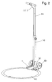
- the top of the lifting arm 1, the top of the side Parts is provided with a concave shape 1.1, on which the hook 25 is supported with lateral pins 21, as Figs. 2 to 7 show.
- the support device has below the side parts 7 in the front free end portion of a flat cover stop surface 3, under which a raised lid is supported with its edge during lifting, as is apparent from Figs. 2 and 4.
- the lid abutment surfaces 3 go over a downwardly directed paragraph in a flat Abstützkufe 4, which lies in front-to-rear direction when coupling the lifter with its front edge slightly before the lower point of the wheels 30.
- the front edge of the flat, straight Abst Reifenkufen results in a stable pivot point when levering the lid and transition to the wheels 30 during the backward pivoting of the hand lever 10th
- the hook 25 can easily slide with the lateral pins on the upper edges of the two lateral parts when applying and moving the hook in the correct position and automatically adjusts optimally for the Aushebelvorgang the lid.
- the hook 25 is held by means of the pin 21 stably on the upper concave edges of the lateral parts.
- the lateral pins are provided with collar-like extensions 20 which engage over the outside of the lateral parts of the lifting arm 1.
- non-rotatable guidance of the hook 25 in the space between the lateral parts of the lifting arm 1 of the hook 25 is provided on both sides in the region of the pin 21 with flange inner guide members.
- the hook 25 protrudes with its lower portion on the lower side of the lifting arm 1 and the lower edges of the two lateral parts and has at its lower portion a forwardly projecting hook portion 22 which is hooked into a corresponding opening of the manhole cover. Between the hook part 22 and the Bottom of the lifting arm 1, the hook 25 is provided with a transverse locking member 23 which may be fixed or detachably attached to the hook 25. With the top of the locking element 22, the hook is supported against the underside of the lifting arm 1 and the lower edges of the lateral parts.
- Characterized the hook between the lateral parts of the lifting arm 1 is easily adjustable and held captive, especially if the distance between the underside of the collar-like extensions 20 of the pin 21 and the top of the locking element 23 is less than the width of the lateral parts in the height direction.
- a simple removal of the hook 25 can alternatively be made possible by the fact that the locking element 23 is detachable.
- a variant of the hook 25 can be designed such that the locking element 23, which is located at a distance from the pin 21 in the lower region of the hook 25, is designed so that the locking element 23 is supported on the lid edge, while the front part 22 of the hook 25 lifts the lid from below.
- the abutment surface 3 of the side parts 7 should be designed at an angle to the lifting arm 1 so that it is supported by the lifting support 4 on the ground after a first lifting, unlocking or loosening phase. Upon further pivoting of the lifting arm 1, the lifting support 4 approaches the ground until the wheels 30 receive the lid load. It is envisaged that the supporting device has at least two spaced-apart, in the position of use near the edge of the lid supported on the ground jacks.
- the supports may consist of a flat iron, which hinfortsum from the support point in the direction of the lower edge of the wheels 30.
Landscapes
- Life Sciences & Earth Sciences (AREA)
- Engineering & Computer Science (AREA)
- Geology (AREA)
- Mechanical Engineering (AREA)
- Structural Engineering (AREA)
- Handcart (AREA)
- Underground Structures, Protecting, Testing And Restoring Foundations (AREA)
Priority Applications (1)
| Application Number | Priority Date | Filing Date | Title |
|---|---|---|---|
| NO20074045A NO20074045L (no) | 2006-08-14 | 2007-08-06 | Loftestang for mannhullokk |
Applications Claiming Priority (1)
| Application Number | Priority Date | Filing Date | Title |
|---|---|---|---|
| DE200620012526 DE202006012526U1 (de) | 2006-08-14 | 2006-08-14 | Heber für Schachtdeckel |
Publications (1)
| Publication Number | Publication Date |
|---|---|
| EP1889809A2 true EP1889809A2 (fr) | 2008-02-20 |
Family
ID=37311642
Family Applications (1)
| Application Number | Title | Priority Date | Filing Date |
|---|---|---|---|
| EP20070011639 Withdrawn EP1889809A2 (fr) | 2006-08-14 | 2007-06-14 | Levier pour dispositif de levage de couvercle |
Country Status (2)
| Country | Link |
|---|---|
| EP (1) | EP1889809A2 (fr) |
| DE (1) | DE202006012526U1 (fr) |
-
2006
- 2006-08-14 DE DE200620012526 patent/DE202006012526U1/de not_active Expired - Lifetime
-
2007
- 2007-06-14 EP EP20070011639 patent/EP1889809A2/fr not_active Withdrawn
Also Published As
| Publication number | Publication date |
|---|---|
| DE202006012526U1 (de) | 2006-10-19 |
Similar Documents
| Publication | Publication Date | Title |
|---|---|---|
| DE102009040200B4 (de) | Transportvorrichtung für ein längliches Objekt | |
| EP2399826B1 (fr) | Dispositif de fixation pour la fixation au moins partielle d'un premier et d'un second colis | |
| EP2698296B1 (fr) | Tube télescopique réglable en longueur | |
| DE60110416T2 (de) | Motorradservicestand | |
| EP3156279B1 (fr) | Vehicule automobile pour le transport de marchandises | |
| EP0042608B1 (fr) | Dispositif de support pour un outillage démontable d'un tracteur | |
| EP1219564B1 (fr) | Dispositif de levage de couvercle de regard ou similaire | |
| DE102009051191A1 (de) | Nachrüstbares Rollenelement und Fuß für ein automatisches Lagersystem sowie Verfahren zum Verschieben eines automatischen Lagersystems | |
| DE202010004388U1 (de) | Plattformlift zur Anbringung an einem Wasserfahrzeug und Wasserfahrzeug mit einem Plattformlift | |
| EP2191707A2 (fr) | Dispositif de dépôt pour une machine de montage à trois points | |
| DE19928574C2 (de) | Arbeitsbühne | |
| DE4036596C1 (en) | Hoist for upright barrels with gripper arms on support body - on which is fitted eccentric disc such as to control holding bar | |
| DE202013104647U1 (de) | Lagervorrichtung für Tierkadaver | |
| EP3089890B1 (fr) | Recouvrement d'un compartiment à bagages d`un véhicule automobile | |
| EP2446772B1 (fr) | Table pliante | |
| WO2012062865A1 (fr) | Moyen d'amarrage et dispositif comprenant un tel moyen d'amarrage pour le levage de charges lourdes | |
| DE102012112757B4 (de) | Bordsteinheber | |
| DE202006012526U1 (de) | Heber für Schachtdeckel | |
| DE202009002002U1 (de) | Schubkastenführung | |
| DE20206078U1 (de) | Allzweck-Deckelheber für Kanal- und Schachtdeckel o.dgl. | |
| AT512201B1 (de) | Einrichtung zur Befestigung eines Laufstegs an einer Faserbahnmaschine, Laufsteg für eine Faserbahnmaschine und Verfahren zur Handhabung eines Laufstegs in Verbindung mit einer Faserbahnmaschine | |
| DE3315813A1 (de) | Anbaubock fuer die dreipunkt-hebevorrichtung eines schleppers | |
| EP3839144B1 (fr) | Equipement porté, en particulier gravillonneuse | |
| DE10211211B4 (de) | Höhenverstellbares Säulenelement für ein Lastfahrzeug | |
| DE10235922B4 (de) | Verfahren zur Veränderung der Fläche des Lastraumes einer Arbeitsmaschine |
Legal Events
| Date | Code | Title | Description |
|---|---|---|---|
| PUAI | Public reference made under article 153(3) epc to a published international application that has entered the european phase |
Free format text: ORIGINAL CODE: 0009012 |
|
| AK | Designated contracting states |
Kind code of ref document: A2 Designated state(s): AT BE BG CH CY CZ DE DK EE ES FI FR GB GR HU IE IS IT LI LT LU LV MC MT NL PL PT RO SE SI SK TR |
|
| AX | Request for extension of the european patent |
Extension state: AL BA HR MK YU |
|
| STAA | Information on the status of an ep patent application or granted ep patent |
Free format text: STATUS: THE APPLICATION IS DEEMED TO BE WITHDRAWN |
|
| 18D | Application deemed to be withdrawn |
Effective date: 20100701 |