EP1889990A2 - Ferrure pour porte ou fenêtre - Google Patents
Ferrure pour porte ou fenêtre Download PDFInfo
- Publication number
- EP1889990A2 EP1889990A2 EP07010999A EP07010999A EP1889990A2 EP 1889990 A2 EP1889990 A2 EP 1889990A2 EP 07010999 A EP07010999 A EP 07010999A EP 07010999 A EP07010999 A EP 07010999A EP 1889990 A2 EP1889990 A2 EP 1889990A2
- Authority
- EP
- European Patent Office
- Prior art keywords
- fitting
- door
- rotation
- axis
- transmission means
- Prior art date
- Legal status (The legal status is an assumption and is not a legal conclusion. Google has not performed a legal analysis and makes no representation as to the accuracy of the status listed.)
- Withdrawn
Links
- 230000005540 biological transmission Effects 0.000 claims abstract description 29
- 230000007246 mechanism Effects 0.000 claims description 9
- 230000001360 synchronised effect Effects 0.000 description 4
- 238000009434 installation Methods 0.000 description 3
- 230000000903 blocking effect Effects 0.000 description 2
- 230000008859 change Effects 0.000 description 2
- 230000008878 coupling Effects 0.000 description 2
- 238000010168 coupling process Methods 0.000 description 2
- 238000005859 coupling reaction Methods 0.000 description 2
- 239000000834 fixative Substances 0.000 description 2
- 238000004519 manufacturing process Methods 0.000 description 2
- 206010052804 Drug tolerance Diseases 0.000 description 1
- 229910000831 Steel Inorganic materials 0.000 description 1
- 230000009286 beneficial effect Effects 0.000 description 1
- 230000001419 dependent effect Effects 0.000 description 1
- 230000000994 depressogenic effect Effects 0.000 description 1
- 230000002349 favourable effect Effects 0.000 description 1
- 239000011521 glass Substances 0.000 description 1
- 230000026781 habituation Effects 0.000 description 1
- 230000001939 inductive effect Effects 0.000 description 1
- 238000003780 insertion Methods 0.000 description 1
- 230000037431 insertion Effects 0.000 description 1
- 230000003993 interaction Effects 0.000 description 1
- 238000002955 isolation Methods 0.000 description 1
- 238000000034 method Methods 0.000 description 1
- 230000000474 nursing effect Effects 0.000 description 1
- 230000008569 process Effects 0.000 description 1
- 230000004044 response Effects 0.000 description 1
- 230000002441 reversible effect Effects 0.000 description 1
- 125000006850 spacer group Chemical group 0.000 description 1
- 239000010959 steel Substances 0.000 description 1
- 230000001960 triggered effect Effects 0.000 description 1
Images



Classifications
-
- E—FIXED CONSTRUCTIONS
- E05—LOCKS; KEYS; WINDOW OR DOOR FITTINGS; SAFES
- E05B—LOCKS; ACCESSORIES THEREFOR; HANDCUFFS
- E05B1/00—Knobs or handles for wings; Knobs, handles, or press buttons for locks or latches on wings
- E05B1/0053—Handles or handle attachments facilitating operation, e.g. by children or burdened persons
-
- E—FIXED CONSTRUCTIONS
- E05—LOCKS; KEYS; WINDOW OR DOOR FITTINGS; SAFES
- E05B—LOCKS; ACCESSORIES THEREFOR; HANDCUFFS
- E05B53/00—Operation or control of locks by mechanical transmissions, e.g. from a distance
-
- E—FIXED CONSTRUCTIONS
- E05—LOCKS; KEYS; WINDOW OR DOOR FITTINGS; SAFES
- E05B—LOCKS; ACCESSORIES THEREFOR; HANDCUFFS
- E05B53/00—Operation or control of locks by mechanical transmissions, e.g. from a distance
- E05B53/001—Foot-operation
Definitions
- the invention relates to a fitting for a door or a window according to the features of claim 1.
- Door fittings with two rotary axes, which act on a locking system are made of DE 101 62 465 B4 and the DE 103 13 711 A1 known. Both documents show door fittings for manually operated swing doors. The door fittings in this case have an additional receptacle for a further operating handle. By means of push rods coupling of the actuators takes place with each other, so that both act on the lock nut. With the disclosed door fittings, the actuators can be positioned according to the requirements of DIN 18030 in grab heights of 850 mm on the door leaf. This allows use by children, the disabled and the elderly. Especially in nursing or retirement homes, it often turns out that elderly or physically disabled people have problems with the door handle mounted according to DIN 18101 at 1050 mm above the top edge of the finished floor. Also wheelchair users can often open doors with standard handles from the hinge side only with great difficulty.
- the fitting has two axes of rotation, wherein at least one of the axes of rotation supports an actuating element.
- the axes of rotation are via a power transmission means connected. This provides in response to an actuation of the actuating element for a synchronous rotation of the first and the second axis of rotation.
- the first axis of rotation is mounted in a lock nut, which retracts the lock in known locking systems.
- the fitting covering the power transmission means is fixed to the fitting by means of a positioning element. During or after assembly of the fitting this can be pivoted about the first axis of rotation.
- the actuator retains its horizontal position relative to the door or window.
- the fitting according to the invention allows a more flexible arrangement on the door or window sash. So is a central positioning of the actuator on the door or window sash - and thus an increase in the effective Domginses - easy and without structural measures possible.
- the horizontal orientation of the handle always remains constant. Consequently, it does not require an adjustment of the actuating element or even the habituation to a new handle alignment after changes in the operating height of the handle. As appropriate, it has been found to set up the fitting so that it is applied horizontally or diagonally on the door leaf. This position allows especially wheelchair users a simple opening of the door from the hinge opposite side.
- the positioning element fixes the fitting according to the invention reversibly releasably on the wing.
- it may be the positioning element to a screw which is screwed through the fitting in the wing.
- changing the position of the fitting leaves screw holes in the wing, which could possibly disturb the aesthetic impression of the viewer.
- the fitting according to the invention can be provided in particular on the first axis of rotation with locking means. By mounting the locking means both on the wing and in the fitting, both could be locked together.
- One of the locking means could have a serrated profile on which the corresponding counter-locking means is pushed and held in position by means of a connecting element, such as a screw.
- the fitting according to the invention can be arranged flexibly depending on the external conditions. This includes on the one hand a variable height, on which the actuating element rests on the wing. Furthermore, with extended fittings, the control element can also be offset horizontally in the direction of the door hinge. It has proved to be particularly advantageous if the actuating element - is positioned relative to the width of the door center.
- the positioning element consists of a holding means and a fixing means.
- the fixative could be integrated in the wing. With him acts a built-in fitting retaining means together. Both could be screwed together by way of example, so as to ensure a permanent and reversible releasable fixation of the fitting on the wing.
- the fixation means may be an insert embedded in the wing.
- a holding cylinder or a retaining lug is conceivable in the region of the first axis of rotation leading to the lock nut.
- the fixing means can be a rail embedded in the wing. With it, the fitting can be adjusted to any height.
- the lock cylinder covering rosette can be formed as a spacer and thus positioning element. Depending on the shape and size of the Rosette, the fitting can be pushed into different positions. By connecting the fitting with the rosette this would receive additional stability.
- the power transmission means has an L-shaped arrangement. This makes it possible to arrange the fitting next to the rosette of the lock cylinder.
- the power transmission means consist of the combination of a transmission and a rack or push rod. By integrating an intermediate axis into the power transmission means, it would be ensured that the directions of rotation of the first and second axes of rotation continue to be synchronous. Also possible is a connection by means of a cable or a spring element.
- the fitting surrounds the rosette of the locking system U-shaped.
- This structure results in a multi-part combination of rosette and fitting.
- the positioning of the actuator below the lock cylinder would facilitate the insertion of the key in selbigen, as a clear view of the lock channel is guaranteed. This arrangement has been found to be very beneficial in terms of usability, especially for the elderly and disabled people.
- the door fitting according to the invention is a foot-operated door fitting with a coupling to the lock nut.
- the fitting with the power transmission means is extended so far that it ends just above the floor.
- This fitting is particularly suitable for applications in which increased hygiene requirements are imposed.
- the door can be unlocked with a toe. From the hinge opposite side, the door can then be opened in a simple manner with the foot.
- the Band side can be activated with the operation of the fitting an additional lever mechanism that supports the initial door movement.
- the closing process can be supported by means of a door closer integrated in the floor or in the door leaf. It is also conceivable that after opening the footrest, the opening movement of the door is performed automatically and independently by a combination of electrical and / or mechanical systems.
- the power transmission means may be configured electrically or electromechanically and by a pressure-sensitive, capacitive or inductive switch, which is mounted in the actuating element, are triggered.
- the actuator may be a round handle, lever, push button, a cleat or a panic bar.
- a pusher lock with which the power transmission means can be blocked. This may be, for example, a pawl which pivots in the path of movement of the rack. In order to allow an emergency opening, if necessary, a legitimate operation by means of a key is possible from the outside.
- the fitting according to the invention can also comprise purely mechanical elements which connect the first and second axes of rotation to one another. These may be push rods, cables, chains, steel belts, gears or racks. It is also conceivable to integrate a return spring in the power transmission element. With it, the load torque, which is caused by the pusher's own weight, be compensated.
- the fitting according to the invention can be used for a variety of different door wings.
- the fitting may have a breakpoint, which is supported on the framed glass surface.
- the fitting can be supported on one, the frame sides connecting bracket.
- the use of the fitting according to the invention is not limited to doors. Rather, he can find an example for windows or the like use.
- various electrical and electronic additional devices such as electromagnetic / electromotive isolation or blocking systems can be integrated in the space of the fitting.
- These access control systems can be supplemented by electro-optic or electro-acoustic condition indicators.
- additional security features such as tamper-proof outer fittings or additional fastening elements, can be integrated in the fitting.
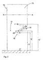
- the fitting 10 is shown schematically, which can be used for both doors and windows.
- the first axis of rotation 20 is connected to the lock nut of the locking system, not shown.
- the lock nut pulls back the closing latch via a lever (not shown here), as a result of which the door or window wing opens by pulling or pushing on the actuating element 40.
- a second axis of rotation 21 is arranged.
- the actuator 40 here a door handle stored.
- the fitting 10 according to the invention has the possibility to shift it in the direction of the center of the door.
- the length of the fitting allows an increase in the effective Domginses.
- the actuating element is displaced in the direction of the door hinge 76 and is now in the region of the vertical center axis on the door leaf. Due to its length, a variation of the height 12 only leads to a small change in the diameter.
- the possibility according to the invention of creating a fitting which also connects two axes of rotation over a greater distance enables a flexible arrangement 11 of the fitting 10 on the door leaf 70.
- the actuating element 40 can not only be installed at different heights 12, 12 ', 12 ". but can also be arranged flexibly on the entire surface of the door leaf, depending on the requirement, the fitting can therefore serve, on the one hand, to locate the actuating element in one greater or lower height than the known backset on the door to position.
- the same fitting can also be used to move the actuator 40 in the direction of the door hinge.
- the fitting according to the invention can combine both possibilities.
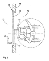
- FIG. 3 shows a section along the section line A-A shown in FIG. It can be seen that the pivoting of the fitting 10 according to the invention, the actuating element 40 - here a door handle - is offset in the direction of the door hinge.
- This positioning of the door opening handle in the region of the vertical center axis of the door allows wheelchair users, in particular, to more easily open the door from the hinge opposite side 73.
- the wheelchair user is generally forced to first position himself parallel to the door to open the door by means of the door handle. Afterwards, he has to change his wheelchair in the direction of the door opening without the door closing again. Due to the special positioning of the fitting 10 according to the invention or the second axis of rotation 21 in the vicinity of the vertical center axis of the door 70, the wheelchair user can drive up directly in front of the door handle and easily push open the door.
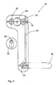
- FIG. 4 shows a further embodiment of the fitting 10 according to the invention.
- the power transmission means 50 has an L-shaped arrangement.
- the rotational movement of the second rotation axis 21 is transmitted via the rack 51 to a pinion which is positioned on the intermediate axis 53.
- This pinion is part of the transmission 52 connected to the first axis of rotation 20. It transmits the rotational movement of the second axis of rotation 21 to the first axis of rotation 20.
- the two axes of rotation 20, 21 lie respectively in the end regions of the L-shaped fitting 10
- Below the first axis of rotation 21 is the rosette 75, which comprises the lock cylinder 32.
- FIG. 5 shows a further embodiment of the fitting 10 according to the invention.
- the fitting 10 is extended so far that it ends just above the top of the finished floor (OFF).
- a footrest 42 is provided.
- This fitting 10 is connected by the power transmission means 50 with the lock nut, so that by foot operation, the lock mechanism is unlocked. Then the door can be pushed open by the hinge opposite side 73 in a simple manner with the foot.
- This actuator 42 lends itself to wherever an opening of the door by hand for reasons of hygiene is not possible or only to a very limited extent.
- an additional lever mechanism 45 may optionally be arranged on the fitting 10 according to the invention.
- This lever mechanism in the illustrated embodiment is an eccentric shaped nose 45. It pushes the door impulsively away from the door frame 71. With appropriate storage and orientation of the door, this short initial pulse is sufficient to fully open the door.
- This purely mechanical door opening aid can be replaced by electrical or hydraulic auxiliary systems that provide for unlocking the lock mechanism for a self-opening of the door leaf 70.
- FIG. 6 shows a section along the section line BB from FIG. 5. This results in the arrangement of the lever mechanism 45 on the hinge side 72 of the door 70 directly next to the footrest 42nd
- the fitting 10 shown in Figure 5 further comprises a control panel 55, It is connected to a pawl which engages in the movement path of the power transmission means 50. This will block the controls on the fitting. This blocking is independent of a locking of the locking system by an actuation of the lock cylinder 32. Rather, it should only be prevented that the actuators can be operated. An optionally required emergency opening from the outside can be made possible via an interaction of the operating part 55 with the lock cylinder / key.
- the fitting 10 according to the invention is shown in a longitudinal section.
- the first axis of rotation 20 passes through the door leaf 70 and is mounted in the lock nut 31.
- the lock nut 31 pulls back on a - not shown here - lever, the latch of the locking system, whereby the door leaf 70 opens by train or pressure on the actuator 40.
- the first rotation axis 20 and the second rotation axis 21 are connected via the power transmission means 50.
- the positioning element 60 is integrated. These are the fixing means 62 fastened to the door leaf 70 by means of two screws 64 and the retaining means 61 integrated in the fitting 10.
- the fixing means 62 is configured in some areas in a cylindrical manner. This, the fitting 10 facing area is enclosed by the holding means 61 positively.
- the fixing means 62 has a connection element 63. It is a grub screw which is mounted in the holding means 61 and can be screwed into the fixing means 62.
- the connecting element 63 is accessible from the outside. Consequently, the connecting element 63 can be released at any time without much effort and the fitting 10 can be aligned in a new position.
- the surface of the fixing means 62 enclosed by the holding means 61 has no structure.
- a continuous rotation of the fitting 10 and fixation of the two positioning elements to each other is possible.
- the fitting 10 could be postponed and held by the connecting element 63.
Landscapes
- Closing And Opening Devices For Wings, And Checks For Wings (AREA)
- Power-Operated Mechanisms For Wings (AREA)
Applications Claiming Priority (1)
| Application Number | Priority Date | Filing Date | Title |
|---|---|---|---|
| DE200610038456 DE102006038456A1 (de) | 2006-08-16 | 2006-08-16 | Beschlag für eine Tür oder Fenster |
Publications (2)
| Publication Number | Publication Date |
|---|---|
| EP1889990A2 true EP1889990A2 (fr) | 2008-02-20 |
| EP1889990A3 EP1889990A3 (fr) | 2009-09-30 |
Family
ID=38828650
Family Applications (1)
| Application Number | Title | Priority Date | Filing Date |
|---|---|---|---|
| EP07010999A Withdrawn EP1889990A3 (fr) | 2006-08-16 | 2007-06-05 | Ferrure pour porte ou fenêtre |
Country Status (2)
| Country | Link |
|---|---|
| EP (1) | EP1889990A3 (fr) |
| DE (1) | DE102006038456A1 (fr) |
Cited By (7)
| Publication number | Priority date | Publication date | Assignee | Title |
|---|---|---|---|---|
| ITRE20090015A1 (it) * | 2009-02-23 | 2010-08-24 | Portarredo S R L | Dispositivo di comando per serrature |
| EP2243905A1 (fr) * | 2009-04-23 | 2010-10-27 | Lamnouar Saad | Agencement d'ouverture et de fermeture du vantail d'une porte ou d'une fenêtre |
| EP2390443A1 (fr) * | 2010-05-31 | 2011-11-30 | Metalux | Panneau de porte comportant un système de serrure |
| CN104141429A (zh) * | 2013-05-06 | 2014-11-12 | 张义兵 | 联动式门把手 |
| US20220154494A1 (en) * | 2020-11-13 | 2022-05-19 | Aztech Industrial Devices LLC | Foot-operated systems and devices for handless operation of a door |
| US20230203858A1 (en) * | 2020-05-20 | 2023-06-29 | Lionel AUDIRAC | Device for locking a door |
| US20230279698A1 (en) * | 2020-11-13 | 2023-09-07 | Aztech Industrial Devices LLC | Foot-operated systems and devices for handless operation of a door |
Citations (2)
| Publication number | Priority date | Publication date | Assignee | Title |
|---|---|---|---|---|
| DE10313711A1 (de) | 2003-03-27 | 2004-10-14 | Steinmetz, Jürgen, Dipl.-Ing. Architekt | Türdrückerschild für die Aufnahme eines zusätzlichen Türdrückerlochteils |
| DE10162465B4 (de) | 2001-03-15 | 2005-11-24 | Andreas Seipel | Türbeschlag |
Family Cites Families (4)
| Publication number | Priority date | Publication date | Assignee | Title |
|---|---|---|---|---|
| US1172205A (en) * | 1915-06-22 | 1916-02-15 | Sanford E Gillentine | Door-opener. |
| US2862750A (en) * | 1956-03-05 | 1958-12-02 | Robert M Minke | Door latch operating mechanism |
| US2928690A (en) * | 1957-07-22 | 1960-03-15 | Wayne F Larson | Door opener |
| FR2866667A1 (fr) * | 2004-02-23 | 2005-08-26 | Der Mye David Harry Van | Dispositif qui selon les cas, permet de rehausser ou d'abaisser une poignee de porte |
-
2006
- 2006-08-16 DE DE200610038456 patent/DE102006038456A1/de not_active Withdrawn
-
2007
- 2007-06-05 EP EP07010999A patent/EP1889990A3/fr not_active Withdrawn
Patent Citations (2)
| Publication number | Priority date | Publication date | Assignee | Title |
|---|---|---|---|---|
| DE10162465B4 (de) | 2001-03-15 | 2005-11-24 | Andreas Seipel | Türbeschlag |
| DE10313711A1 (de) | 2003-03-27 | 2004-10-14 | Steinmetz, Jürgen, Dipl.-Ing. Architekt | Türdrückerschild für die Aufnahme eines zusätzlichen Türdrückerlochteils |
Cited By (12)
| Publication number | Priority date | Publication date | Assignee | Title |
|---|---|---|---|---|
| ITRE20090015A1 (it) * | 2009-02-23 | 2010-08-24 | Portarredo S R L | Dispositivo di comando per serrature |
| EP2243905A1 (fr) * | 2009-04-23 | 2010-10-27 | Lamnouar Saad | Agencement d'ouverture et de fermeture du vantail d'une porte ou d'une fenêtre |
| FR2944824A1 (fr) * | 2009-04-23 | 2010-10-29 | Lamnouar Saad | Agencement d'ouverture et de fermeture du ventail d'une porte ou d'une fenetre |
| EP2390443A1 (fr) * | 2010-05-31 | 2011-11-30 | Metalux | Panneau de porte comportant un système de serrure |
| FR2960583A1 (fr) * | 2010-05-31 | 2011-12-02 | Metalux | Panneau de porte comportant un systeme de serrure |
| CN104141429A (zh) * | 2013-05-06 | 2014-11-12 | 张义兵 | 联动式门把手 |
| US20230203858A1 (en) * | 2020-05-20 | 2023-06-29 | Lionel AUDIRAC | Device for locking a door |
| US12404706B2 (en) * | 2020-05-20 | 2025-09-02 | Lionel AUDIRAC | Device for locking a door |
| US20220154494A1 (en) * | 2020-11-13 | 2022-05-19 | Aztech Industrial Devices LLC | Foot-operated systems and devices for handless operation of a door |
| US20230279698A1 (en) * | 2020-11-13 | 2023-09-07 | Aztech Industrial Devices LLC | Foot-operated systems and devices for handless operation of a door |
| US12024926B2 (en) * | 2020-11-13 | 2024-07-02 | Aztech Industrial Devices LLC | Foot-operated systems and devices for handless operation of a door |
| US12404699B2 (en) | 2020-11-13 | 2025-09-02 | Aztech Industrial Devices LLC | Foot-operated systems and devices for handless operation of a door |
Also Published As
| Publication number | Publication date |
|---|---|
| DE102006038456A1 (de) | 2008-02-21 |
| EP1889990A3 (fr) | 2009-09-30 |
Similar Documents
| Publication | Publication Date | Title |
|---|---|---|
| WO2019011527A1 (fr) | Système de poignée de porte d'un véhicule automobile | |
| DE102006011263A1 (de) | Verriegelungssystem für eine Tür | |
| EP3219885B1 (fr) | Barre de poussée comprenant un dispositif d'entraînement modulaire | |
| EP3219886B1 (fr) | Barre de poussée comprenant un dispositif d'entraînement | |
| EP1921233B1 (fr) | Entraînement de commande pouvant être rééquipé pour une porte pivotante ou analogue | |
| DE102020005193A1 (de) | Notentriegelung für Falttüren mit hygienischem Schnellmontagesystem für Drückergarnituren | |
| EP3401475B1 (fr) | Système d'armatures | |
| DE20203565U1 (de) | Schließvorrichtung | |
| EP1283934B1 (fr) | Systeme de fermeture de portes automobile avec deverrouillage rapide | |
| EP3406829B1 (fr) | Ferrure de porte pour une fermeture anti-panique et fermeture anti-panique | |
| EP2536907B1 (fr) | Dispositif de securite | |
| EP1302615B1 (fr) | Fenêtre ou porte avec ferrure à crémone | |
| DE102006038456A1 (de) | Beschlag für eine Tür oder Fenster | |
| EP2520746B1 (fr) | Serrure actionnée de manière électrique | |
| EP0556553A1 (fr) | Système de commande d'une serrure de porte, notamment pour serrure de porte anti-panique | |
| EP2206862A2 (fr) | Engrenage de languettes destiné au verrouillage ou au déverrouillage d'un volet coulissant | |
| DE19652599C2 (de) | Ent- und Verriegelung für eine einen Standflügel und einen Gangflügel aufweisende Tür | |
| EP3219887B1 (fr) | Barre de poussée | |
| DE29619007U1 (de) | Verriegelungsvorrichtung | |
| DE202015004163U1 (de) | Behindertengerechter Stangenbeschlag mit durchgehend glatter Oberfläche, Notentriegelung und Freilauf für öffnungsschließende Elemente | |
| EP2472041A2 (fr) | Plaque de montage | |
| AT395630B (de) | Doppelfluegelige brandschutztuer | |
| EP0845566A2 (fr) | Unité de battant | |
| EP4610458B1 (fr) | Barre de poussée anti-panique avec ouverture de porte | |
| EP1790804B1 (fr) | Mecanisme d'actionnement à levier pour une crémone |
Legal Events
| Date | Code | Title | Description |
|---|---|---|---|
| PUAI | Public reference made under article 153(3) epc to a published international application that has entered the european phase |
Free format text: ORIGINAL CODE: 0009012 |
|
| AK | Designated contracting states |
Kind code of ref document: A2 Designated state(s): AT BE BG CH CY CZ DE DK EE ES FI FR GB GR HU IE IS IT LI LT LU LV MC MT NL PL PT RO SE SI SK TR |
|
| AX | Request for extension of the european patent |
Extension state: AL BA HR MK YU |
|
| PUAL | Search report despatched |
Free format text: ORIGINAL CODE: 0009013 |
|
| AK | Designated contracting states |
Kind code of ref document: A3 Designated state(s): AT BE BG CH CY CZ DE DK EE ES FI FR GB GR HU IE IS IT LI LT LU LV MC MT NL PL PT RO SE SI SK TR |
|
| AX | Request for extension of the european patent |
Extension state: AL BA HR MK RS |
|
| 17P | Request for examination filed |
Effective date: 20100330 |
|
| 17Q | First examination report despatched |
Effective date: 20100506 |
|
| AKX | Designation fees paid |
Designated state(s): AT BE BG CH CY CZ DE DK EE ES FI FR GB GR HU IE IS IT LI LT LU LV MC MT NL PL PT RO SE SI SK TR |
|
| RAP1 | Party data changed (applicant data changed or rights of an application transferred) |
Owner name: DORMA GMBH + CO. KG |
|
| STAA | Information on the status of an ep patent application or granted ep patent |
Free format text: STATUS: THE APPLICATION HAS BEEN WITHDRAWN |
|
| 18W | Application withdrawn |
Effective date: 20150722 |