EP1890101A1 - Ailette pour échangeur de chaleur, échangeur de chaleur avec une telle ailette et procédé pour fabriquer l'échangeur de chaleur - Google Patents
Ailette pour échangeur de chaleur, échangeur de chaleur avec une telle ailette et procédé pour fabriquer l'échangeur de chaleur Download PDFInfo
- Publication number
- EP1890101A1 EP1890101A1 EP06016505A EP06016505A EP1890101A1 EP 1890101 A1 EP1890101 A1 EP 1890101A1 EP 06016505 A EP06016505 A EP 06016505A EP 06016505 A EP06016505 A EP 06016505A EP 1890101 A1 EP1890101 A1 EP 1890101A1
- Authority
- EP
- European Patent Office
- Prior art keywords
- collar
- rib
- heat exchanger
- ribs
- function
- Prior art date
- Legal status (The legal status is an assumption and is not a legal conclusion. Google has not performed a legal analysis and makes no representation as to the accuracy of the status listed.)
- Granted
Links
Images
Classifications
-
- F—MECHANICAL ENGINEERING; LIGHTING; HEATING; WEAPONS; BLASTING
- F28—HEAT EXCHANGE IN GENERAL
- F28F—DETAILS OF HEAT-EXCHANGE AND HEAT-TRANSFER APPARATUS, OF GENERAL APPLICATION
- F28F1/00—Tubular elements; Assemblies of tubular elements
- F28F1/10—Tubular elements and assemblies thereof with means for increasing heat-transfer area, e.g. with fins, with projections, with recesses
- F28F1/12—Tubular elements and assemblies thereof with means for increasing heat-transfer area, e.g. with fins, with projections, with recesses the means being only outside the tubular element
- F28F1/24—Tubular elements and assemblies thereof with means for increasing heat-transfer area, e.g. with fins, with projections, with recesses the means being only outside the tubular element and extending transversely
- F28F1/32—Tubular elements and assemblies thereof with means for increasing heat-transfer area, e.g. with fins, with projections, with recesses the means being only outside the tubular element and extending transversely the means having portions engaging further tubular elements
- F28F1/325—Fins with openings
-
- F—MECHANICAL ENGINEERING; LIGHTING; HEATING; WEAPONS; BLASTING
- F28—HEAT EXCHANGE IN GENERAL
- F28F—DETAILS OF HEAT-EXCHANGE AND HEAT-TRANSFER APPARATUS, OF GENERAL APPLICATION
- F28F1/00—Tubular elements; Assemblies of tubular elements
- F28F1/10—Tubular elements and assemblies thereof with means for increasing heat-transfer area, e.g. with fins, with projections, with recesses
- F28F1/12—Tubular elements and assemblies thereof with means for increasing heat-transfer area, e.g. with fins, with projections, with recesses the means being only outside the tubular element
- F28F1/24—Tubular elements and assemblies thereof with means for increasing heat-transfer area, e.g. with fins, with projections, with recesses the means being only outside the tubular element and extending transversely
-
- F—MECHANICAL ENGINEERING; LIGHTING; HEATING; WEAPONS; BLASTING
- F28—HEAT EXCHANGE IN GENERAL
- F28F—DETAILS OF HEAT-EXCHANGE AND HEAT-TRANSFER APPARATUS, OF GENERAL APPLICATION
- F28F1/00—Tubular elements; Assemblies of tubular elements
- F28F1/10—Tubular elements and assemblies thereof with means for increasing heat-transfer area, e.g. with fins, with projections, with recesses
- F28F1/12—Tubular elements and assemblies thereof with means for increasing heat-transfer area, e.g. with fins, with projections, with recesses the means being only outside the tubular element
- F28F1/24—Tubular elements and assemblies thereof with means for increasing heat-transfer area, e.g. with fins, with projections, with recesses the means being only outside the tubular element and extending transversely
- F28F1/32—Tubular elements and assemblies thereof with means for increasing heat-transfer area, e.g. with fins, with projections, with recesses the means being only outside the tubular element and extending transversely the means having portions engaging further tubular elements
-
- F—MECHANICAL ENGINEERING; LIGHTING; HEATING; WEAPONS; BLASTING
- F28—HEAT EXCHANGE IN GENERAL
- F28F—DETAILS OF HEAT-EXCHANGE AND HEAT-TRANSFER APPARATUS, OF GENERAL APPLICATION
- F28F2275/00—Fastening; Joining
- F28F2275/12—Fastening; Joining by methods involving deformation of the elements
- F28F2275/125—Fastening; Joining by methods involving deformation of the elements by bringing elements together and expanding
Definitions
- the invention relates to a rib for a heat exchanger according to the preamble of claim 1, a heat exchanger according to the preamble of claim 10 and a method for producing the heat exchanger according to the preamble of claim 14.
- the ribs have openings with collar, so-called passages, for receiving flat tubes.
- the ribs are stacked at a certain distance, the so-called rib pitch, and the tubes are inserted into the passages, which is preferably done automatically.
- Tubes and ribs of the known system consist of aluminum or aluminum alloys and are soldered together in the area of the passages.
- the known rib has between the passages gill fields and turbulators, which also serve to produce the rib spacing. Since the turbulators are arranged in the area of the gill fields, there is a loss of thermodynamic performance due to a poorer heat transfer.
- the problem underlying the invention is to make a rib with spacers and passage thermodynamically and manufacturing technology favorable.
- soldered systems it is also known to make the rib spacing by spacers outside the gill area.
- a solderable heat exchanger block has been known, which consists of flat ribs and flat tubes, wherein the ribs have passage openings for the tubes and the openings enclosing collar with a bent-up spacer tab.
- the spacer flap is part of a collar section and towers above it in height.
- the collar portions and the spacer tabs have different functions: the collar portions lie over a large part of the circumference of the flat tube and are soldered to it.
- the raised spacer plates are used to fix the distance in the stacking of the flat ribs, they are claimed in this layering process to pressure or buckling.
- the spacer tab Since in the known rib, the spacer tab is physically connected to the collar, there is a mutual influence of the functions.
- the disadvantage here is that the soldering gap can be increased inadmissible by the pressure and buckling of the spacer, resulting in insufficient soldering and thus to a reduced thermal performance of the heat exchanger.
- the collar which surrounds the openings for receiving the flat tubes assumes both the function of a contact surface and the function of spacing, these two functions being separated from one another in such a way that they do not mutually engage one another. influence negatively.
- the spacer function compressing stress of the collar
- the pressing force of the collar for fixing the ribs on the tube is not impaired - rather, the collar can maintain an undiminished tension or contact pressure on the flat tube.
- the separation of functions takes place in that the collar - seen in the circumferential direction - is divided into individual subregions, wherein the subsections perform the same or different functions.
- at least two first partial areas can only assume the function of pressing the collar onto the flat tube, and at least one second partial area can exclusively perform the function of spacing.
- the separation of the functions or the subregions can be advantageously carried out by separating cuts, distributed over the circumference of the collar.
- the collar is thus separated into individual sections, which result in a fan-shaped collar which encompasses the circumference of the flat tube.
- contact surfaces and spacers can be provided by a third portion of another function, namely the flow influencing by appropriate design of the third portion.
- the surface of the collar is used to further improve the heat transfer through the third sections in the form of flow-influencing elements.
- the object of the invention is also achieved by the features of claim 10 for a heat exchanger, which is equipped with the rib according to the invention.
- the thermodynamic performance of the heat exchanger can be increased and the manufacturing costs reduced.
- flat tubes and ribs made of aluminum or aluminum alloys and are connected by brazing materially.
- the advantage of a higher heat transfer performance is achieved.
- the solder gaps between the collar and flat tubes are conical. This results in the advantage that a mechanical production (threading of the tubes in the collar openings) is possible and by the solder seam reinforcing the pipe cross-section is achieved.
- the object of the invention is finally achieved by a method having the features of claim 14.
- the first partial regions according to the invention serve as contact surfaces and on the one hand cause a fixation of the rib and tube and on the other hand ensure the securing of a defined solder gap to achieve a defect-free soldering.
- the second subregions in the form of spacers ensure the specified rib spacing (rib pitch) when the ribs are stacked on one another.
- the inventive method thus has the advantage of a higher process reliability, since the required process parameters soldering and rib division can be maintained with greater security. This lowers the manufacturing costs of the heat exchanger.
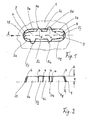
- FIG. 1 shows a plan view of a substantially planar rib 1 arranged in the plane of the drawing, which has an opening 2 with a collar 3 having.
- the rib 1 is part of a not shown. Ribbed packet, which is connected to the openings 2, not shown flat tubes, preferably by soldering.
- the collar 3 and the rib 1 are made in one piece from a thin sheet, preferably made of aluminum or an aluminum alloy, wherein the material thickness of the ribs 1 is in the range of hundredths of a millimeter.
- the opening 2 is formed as a slot for receiving the flat tubes, not shown, and has - distributed over the circumference - a plurality of partially differently shaped collar portions 3a to 3l, which are separated by column 4 from each other.
- the collar portions 3a to 3l have partly the same, sometimes different functions:
- the collar portion 3a, 3c, 3e, 3g, 3i, 3k have the function of contact surfaces, which create the narrowest possible and with a defined gap width of the flat tube, not shown , The latter also applies to the arranged on the narrow sides of the elongated hole 2 collar portions 3f, 3l, which simultaneously serve a longitudinal centering of the flat tube in the opening 2.
- the collar sections 3d, 3j which are arranged on opposite longitudinal sides, have the function of spacers; they are therefore bent at its free end (lying above the plane of the drawing) parallel to the plane of the rib 1 to the outside and form semicircular contact surfaces for the next following rib.
- the collar sections 3b, 3h have the function of flow-guiding or flow-influencing elements, for example, for generating a turbulent flow of a collar surrounding the outside of the medium, in particular air, whose flow direction is represented by an arrow L.
- the collar sections 3b, 3h issued to the outside, ie from the oval contour of the collar 3 to the outside.
- a turbulence therefore results behind the flow-influencing elements 3b, 3h as a result of a stall on the outer edge.
- This increases the heat transfer in the region of the longitudinal sides of the flat tube.
- the illustrated geometry and the arrangement of the collar sections 3a to 3l are exemplary, they can be varied within the scope of the invention. It is essential, however, that the collar sections, which perform different functions, are separated from each other, so that there is no mutual unfavorable influence.
- the collar sections 3a, 3c, 3e, 3g, 3i, 3k are (in the circumferential direction) relatively long sections in order to achieve a substantial contact with the flat tube.
- the collar sections 3d, 3j for spacing can be formed relatively short (viewed in the circumferential direction). The same applies to the flow-guiding elements 3b, 3h.
- FIG. 2 shows a view of the collar 3 with the collar sections 3g, 3i, 3k and 3f, 31 for contact keeping, the collar section 3j for spacing and the collar section 3h for influencing the flow outside the flat tube.
- the collar 3 has an upper edge b and a height t, which extends from the rib plane 1 (shown in phantom) to the upper edge b and corresponds to the rib pitch. From both Figures 1 and 2 it can be seen that the individual sections, possibly with the exception of the flow-influencing elements 3b, 3h are arranged conically to the longitudinal direction of the flat tube, ie they form before and after the threading of the flat tube in the rib 1 a conical_Spalt, in particular in the soldering of rib and tube is advantageous.
- the collar portions 3a to 31 at least partially form perpendicular to the rib plane, in the manner of a passage, which has substantially cylindrical walls.
- the separation gaps 4 between the individual collar sections 3g to 3l are particularly clearly visible; the gaps 4 extend from the upper edge b of the collar 3 down to the dash-dotted line indicated rib plane 1 and thus cause a physical separation of the sections 3g to 3l in the circumferential direction from each other, as well as not visible in Fig. 2 sections 3a to 3e.
- This physical separation leads to a separation of the functions of the individual sections, which is explained by the following example
- the ribs 1 provided with openings 2 and collar 3 are laminated into a package, the spacers 3g, 3j providing a spacing of the ribs to a predetermined extent, the rib pitch t.
- the flat tubes preferably automatically threaded or inserted.
- the contact portions 3a, 3c, 3e, 3g, 3i, 3k and 3f, 31 fit tightly against the circumference of the flat tube.
- the ribs are pressed against each other due to friction between the flat tube and collar 3, wherein this pressure load is absorbed by the spacers 3d, 3j.
- These are designed and designed for this purpose - yet deformations may occur, which are not transmitted due to separation through the column 4 on the adjacent contact sections - the latter are thus not affected by such a pressure load in their effect as contact surfaces for generating a defined contact force, as they are isolated by the separation column 4.
- the preparation of the openings 2 with collar 3 and 4 columns can be analogous to the aforementioned DE 197 41 856 A1 Applicant done, ie by making cuts and embossing the collar sections 3a to 31, ie without punching waste.
Landscapes
- Physics & Mathematics (AREA)
- Engineering & Computer Science (AREA)
- Geometry (AREA)
- Thermal Sciences (AREA)
- Mechanical Engineering (AREA)
- General Engineering & Computer Science (AREA)
- Heat-Exchange Devices With Radiators And Conduit Assemblies (AREA)
Priority Applications (2)
| Application Number | Priority Date | Filing Date | Title |
|---|---|---|---|
| DE200650005252 DE502006005252D1 (de) | 2006-08-08 | 2006-08-08 | Rippe für einen Wärmeübertrager, Wärmeübertrager mit einer solchen Rippe und Verfahren zur Herstellung des Wärmeübertragers |
| EP20060016505 EP1890101B1 (fr) | 2006-08-08 | 2006-08-08 | Ailette pour échangeur de chaleur, échangeur de chaleur avec une telle ailette et procédé pour fabriquer l'échangeur de chaleur |
Applications Claiming Priority (1)
| Application Number | Priority Date | Filing Date | Title |
|---|---|---|---|
| EP20060016505 EP1890101B1 (fr) | 2006-08-08 | 2006-08-08 | Ailette pour échangeur de chaleur, échangeur de chaleur avec une telle ailette et procédé pour fabriquer l'échangeur de chaleur |
Publications (2)
| Publication Number | Publication Date |
|---|---|
| EP1890101A1 true EP1890101A1 (fr) | 2008-02-20 |
| EP1890101B1 EP1890101B1 (fr) | 2009-10-28 |
Family
ID=37307493
Family Applications (1)
| Application Number | Title | Priority Date | Filing Date |
|---|---|---|---|
| EP20060016505 Not-in-force EP1890101B1 (fr) | 2006-08-08 | 2006-08-08 | Ailette pour échangeur de chaleur, échangeur de chaleur avec une telle ailette et procédé pour fabriquer l'échangeur de chaleur |
Country Status (2)
| Country | Link |
|---|---|
| EP (1) | EP1890101B1 (fr) |
| DE (1) | DE502006005252D1 (fr) |
Cited By (6)
| Publication number | Priority date | Publication date | Assignee | Title |
|---|---|---|---|---|
| DE102012002234A1 (de) * | 2012-02-04 | 2013-08-08 | Volkswagen Aktiengesellschaft | Wärmetauscher mit mehreren Lamellen und Verfahren zur Herstellung einer Lamelle für einen Wärmetauscher |
| WO2016198664A1 (fr) * | 2015-06-12 | 2016-12-15 | Valeo Systemes Thermiques | Ailette d'un échangeur thermique notamment pour véhicule automobile, et échangeur thermique correspondant |
| DE202017103235U1 (de) * | 2017-05-30 | 2018-08-31 | Autokühler GmbH & Co KG | Wärmeaustauscher |
| CN112344763A (zh) * | 2019-08-07 | 2021-02-09 | 丹佛斯有限公司 | 制造换热器的方法 |
| DE112017002007B4 (de) | 2016-04-15 | 2024-07-04 | Mitsubishi Electric Corporation | Wärmetauscher |
| CN120558005A (zh) * | 2025-08-01 | 2025-08-29 | 甘肃蓝科石化高新装备股份有限公司 | 一种单侧翅顶开圆弧缺口并在圆弧轮廓线开齿的蛇形翅片簇 |
Citations (3)
| Publication number | Priority date | Publication date | Assignee | Title |
|---|---|---|---|---|
| GB790695A (en) * | 1941-05-13 | 1958-02-12 | Albert Bertholdt Henninger | Method of producing tubular radiators, particularly of aluminium or aluminium alloys |
| EP0672882A1 (fr) * | 1994-02-16 | 1995-09-20 | Behr GmbH & Co. | Ailette pour échangeur de chaleur |
| US20050155750A1 (en) * | 2004-01-20 | 2005-07-21 | Mitchell Paul L. | Brazed plate fin heat exchanger |
-
2006
- 2006-08-08 DE DE200650005252 patent/DE502006005252D1/de active Active
- 2006-08-08 EP EP20060016505 patent/EP1890101B1/fr not_active Not-in-force
Patent Citations (3)
| Publication number | Priority date | Publication date | Assignee | Title |
|---|---|---|---|---|
| GB790695A (en) * | 1941-05-13 | 1958-02-12 | Albert Bertholdt Henninger | Method of producing tubular radiators, particularly of aluminium or aluminium alloys |
| EP0672882A1 (fr) * | 1994-02-16 | 1995-09-20 | Behr GmbH & Co. | Ailette pour échangeur de chaleur |
| US20050155750A1 (en) * | 2004-01-20 | 2005-07-21 | Mitchell Paul L. | Brazed plate fin heat exchanger |
Cited By (7)
| Publication number | Priority date | Publication date | Assignee | Title |
|---|---|---|---|---|
| DE102012002234A1 (de) * | 2012-02-04 | 2013-08-08 | Volkswagen Aktiengesellschaft | Wärmetauscher mit mehreren Lamellen und Verfahren zur Herstellung einer Lamelle für einen Wärmetauscher |
| WO2016198664A1 (fr) * | 2015-06-12 | 2016-12-15 | Valeo Systemes Thermiques | Ailette d'un échangeur thermique notamment pour véhicule automobile, et échangeur thermique correspondant |
| FR3037388A1 (fr) * | 2015-06-12 | 2016-12-16 | Valeo Systemes Thermiques | Ailette d'un echangeur thermique notamment pour vehicule automobile, et echangeur thermique correspondant |
| DE112017002007B4 (de) | 2016-04-15 | 2024-07-04 | Mitsubishi Electric Corporation | Wärmetauscher |
| DE202017103235U1 (de) * | 2017-05-30 | 2018-08-31 | Autokühler GmbH & Co KG | Wärmeaustauscher |
| CN112344763A (zh) * | 2019-08-07 | 2021-02-09 | 丹佛斯有限公司 | 制造换热器的方法 |
| CN120558005A (zh) * | 2025-08-01 | 2025-08-29 | 甘肃蓝科石化高新装备股份有限公司 | 一种单侧翅顶开圆弧缺口并在圆弧轮廓线开齿的蛇形翅片簇 |
Also Published As
| Publication number | Publication date |
|---|---|
| DE502006005252D1 (de) | 2009-12-10 |
| EP1890101B1 (fr) | 2009-10-28 |
Similar Documents
| Publication | Publication Date | Title |
|---|---|---|
| EP0672882B1 (fr) | Ailette pour échangeur de chaleur | |
| EP1703243B1 (fr) | Échangeur de chaleur avec tubes et ailettes et procédé de fabrication | |
| DE60111469T2 (de) | Wärmetauscher und Verfahren zu dessen Herstellung | |
| DE69210452T2 (de) | Wärmetauscher mit Rohrbündel, insbesondere für Kraftfahrzeug | |
| DE69804007T2 (de) | Verfahren zum zusammensetzen von wärmetauscher | |
| DE69215506T2 (de) | Wärmetauschersammlerrohr und Verfahren zu dessen Herstellung | |
| EP0389970B1 (fr) | Echangeur de chaleur comportant des ailettes | |
| EP3359902A1 (fr) | Lamelle pour un échangeur de chaleur à plaques et procédé de fabrication associé | |
| DE112008001782B4 (de) | Wärmetauscher | |
| DE69600309T2 (de) | Flachrohr für einen wärmetauscher | |
| EP1518043A2 (fr) | Echangeur thermique pour gaz d'echappement et procede de fabrication associe | |
| DE202014105709U1 (de) | Wärmeaustauscher | |
| DE3834822A1 (de) | Waermetauscher | |
| DE10150213A1 (de) | Stranggepreßtes Profil, insbesondere für Wärmetauscher | |
| EP1227291B1 (fr) | Echangeur de chaleur et procédé de fabrication | |
| DE102012022302A1 (de) | Spiraltauscher und Verfahren zur Herstellung eines derartigen Tauschers | |
| EP1890101B1 (fr) | Ailette pour échangeur de chaleur, échangeur de chaleur avec une telle ailette et procédé pour fabriquer l'échangeur de chaleur | |
| DE2113581A1 (de) | Flachrohr und Verfahren zum Herstellen desselben | |
| EP0305665B1 (fr) | Echangeur de chaleur avec des ailettes à lamelle | |
| DE102005055420B4 (de) | Thermischer Entlastungsmechanismus für kombinierte Wärmetauscher | |
| DE102004007510B4 (de) | Wärmeübertrager, insbesondere Ölkühler für Kraftfahrzeuge | |
| DE102006002932B4 (de) | Wärmetauscher und Herstellungsverfahren für Wärmetauscher | |
| EP0268831B1 (fr) | Lamelle | |
| EP1321734A1 (fr) | Echangeur de chaleur à tubes plats et procédé de fabrication | |
| EP1985956B1 (fr) | Plaque tubulaire pour récupérateur de chaleur |
Legal Events
| Date | Code | Title | Description |
|---|---|---|---|
| PUAI | Public reference made under article 153(3) epc to a published international application that has entered the european phase |
Free format text: ORIGINAL CODE: 0009012 |
|
| AK | Designated contracting states |
Kind code of ref document: A1 Designated state(s): AT BE BG CH CY CZ DE DK EE ES FI FR GB GR HU IE IS IT LI LT LU LV MC NL PL PT RO SE SI SK TR |
|
| AX | Request for extension of the european patent |
Extension state: AL BA HR MK YU |
|
| 17P | Request for examination filed |
Effective date: 20080820 |
|
| 17Q | First examination report despatched |
Effective date: 20080929 |
|
| AKX | Designation fees paid |
Designated state(s): DE FR GB |
|
| GRAP | Despatch of communication of intention to grant a patent |
Free format text: ORIGINAL CODE: EPIDOSNIGR1 |
|
| GRAS | Grant fee paid |
Free format text: ORIGINAL CODE: EPIDOSNIGR3 |
|
| GRAA | (expected) grant |
Free format text: ORIGINAL CODE: 0009210 |
|
| AK | Designated contracting states |
Kind code of ref document: B1 Designated state(s): DE FR GB |
|
| REG | Reference to a national code |
Ref country code: GB Ref legal event code: FG4D Free format text: NOT ENGLISH |
|
| REF | Corresponds to: |
Ref document number: 502006005252 Country of ref document: DE Date of ref document: 20091210 Kind code of ref document: P |
|
| PLBE | No opposition filed within time limit |
Free format text: ORIGINAL CODE: 0009261 |
|
| STAA | Information on the status of an ep patent application or granted ep patent |
Free format text: STATUS: NO OPPOSITION FILED WITHIN TIME LIMIT |
|
| 26N | No opposition filed |
Effective date: 20100729 |
|
| PGFP | Annual fee paid to national office [announced via postgrant information from national office to epo] |
Ref country code: GB Payment date: 20100825 Year of fee payment: 5 |
|
| PGFP | Annual fee paid to national office [announced via postgrant information from national office to epo] |
Ref country code: FR Payment date: 20110830 Year of fee payment: 6 |
|
| GBPC | Gb: european patent ceased through non-payment of renewal fee |
Effective date: 20110808 |
|
| PG25 | Lapsed in a contracting state [announced via postgrant information from national office to epo] |
Ref country code: GB Free format text: LAPSE BECAUSE OF NON-PAYMENT OF DUE FEES Effective date: 20110808 |
|
| REG | Reference to a national code |
Ref country code: FR Ref legal event code: ST Effective date: 20130430 |
|
| PG25 | Lapsed in a contracting state [announced via postgrant information from national office to epo] |
Ref country code: FR Free format text: LAPSE BECAUSE OF NON-PAYMENT OF DUE FEES Effective date: 20120831 |
|
| REG | Reference to a national code |
Ref country code: DE Ref legal event code: R082 Ref document number: 502006005252 Country of ref document: DE Representative=s name: GRAUEL, ANDREAS, DIPL.-PHYS. DR. RER. NAT., DE |
|
| REG | Reference to a national code |
Ref country code: DE Ref legal event code: R081 Ref document number: 502006005252 Country of ref document: DE Owner name: MAHLE INTERNATIONAL GMBH, DE Free format text: FORMER OWNER: BEHR GMBH & CO. KG, FRAPE BEHR S.A., , ES Effective date: 20150515 Ref country code: DE Ref legal event code: R082 Ref document number: 502006005252 Country of ref document: DE Representative=s name: GRAUEL, ANDREAS, DIPL.-PHYS. DR. RER. NAT., DE Effective date: 20150515 Ref country code: DE Ref legal event code: R081 Ref document number: 502006005252 Country of ref document: DE Owner name: MAHLE INTERNATIONAL GMBH, DE Free format text: FORMER OWNERS: BEHR GMBH & CO. KG, 70469 STUTTGART, DE; FRAPE BEHR S.A., BARCELONA, ES Effective date: 20150515 |
|
| PGFP | Annual fee paid to national office [announced via postgrant information from national office to epo] |
Ref country code: DE Payment date: 20180831 Year of fee payment: 13 |
|
| REG | Reference to a national code |
Ref country code: DE Ref legal event code: R119 Ref document number: 502006005252 Country of ref document: DE |
|
| PG25 | Lapsed in a contracting state [announced via postgrant information from national office to epo] |
Ref country code: DE Free format text: LAPSE BECAUSE OF NON-PAYMENT OF DUE FEES Effective date: 20200303 |