EP1890125A1 - Abgasverdünnungsvorrichtung - Google Patents
Abgasverdünnungsvorrichtung Download PDFInfo
- Publication number
- EP1890125A1 EP1890125A1 EP06756477A EP06756477A EP1890125A1 EP 1890125 A1 EP1890125 A1 EP 1890125A1 EP 06756477 A EP06756477 A EP 06756477A EP 06756477 A EP06756477 A EP 06756477A EP 1890125 A1 EP1890125 A1 EP 1890125A1
- Authority
- EP
- European Patent Office
- Prior art keywords
- exhaust gas
- dilution
- pipe
- gas supply
- circulation pipe
- Prior art date
- Legal status (The legal status is an assumption and is not a legal conclusion. Google has not performed a legal analysis and makes no representation as to the accuracy of the status listed.)
- Granted
Links
Images





Classifications
-
- G—PHYSICS
- G01—MEASURING; TESTING
- G01N—INVESTIGATING OR ANALYSING MATERIALS BY DETERMINING THEIR CHEMICAL OR PHYSICAL PROPERTIES
- G01N1/00—Sampling; Preparing specimens for investigation
- G01N1/02—Devices for withdrawing samples
- G01N1/22—Devices for withdrawing samples in the gaseous state
-
- G—PHYSICS
- G01—MEASURING; TESTING
- G01N—INVESTIGATING OR ANALYSING MATERIALS BY DETERMINING THEIR CHEMICAL OR PHYSICAL PROPERTIES
- G01N1/00—Sampling; Preparing specimens for investigation
- G01N1/02—Devices for withdrawing samples
- G01N1/22—Devices for withdrawing samples in the gaseous state
- G01N1/2247—Sampling from a flowing stream of gas
- G01N1/2252—Sampling from a flowing stream of gas in a vehicle exhaust
-
- G—PHYSICS
- G01—MEASURING; TESTING
- G01N—INVESTIGATING OR ANALYSING MATERIALS BY DETERMINING THEIR CHEMICAL OR PHYSICAL PROPERTIES
- G01N1/00—Sampling; Preparing specimens for investigation
- G01N1/02—Devices for withdrawing samples
- G01N1/22—Devices for withdrawing samples in the gaseous state
- G01N1/2247—Sampling from a flowing stream of gas
- G01N2001/2264—Sampling from a flowing stream of gas with dilution
Definitions
- This invention relates to an exhaust gas dilution device that dilutes exhaust gas in order to analyze material components contained in the exhaust gas of automobiles.
- an exhaust gas dilution device that dilutes the exhaust gas by adding air for dilution is used.
- this kind of the exhaust gas dilution device extracts (samples) exhaust gas of an automobile and circulates the extracted exhaust gas to an analyzer through an exhaust gas circulation pipe as shown in, for example, the patent document 1 and the patent document 2. Then the exhaust gas is diluted by mixing the dilution gas to be supplied to the dilution gas supply pipe at a predetermined ratio in a mixing section arranged on the exhaust gas circulation pipe.
- the dilution gas supply pipe makes a contact with the exhaust gas circulation pipe until the dilution gas is supplied to the mixing section or the dilution gas supplied from the dilution gas supply pipe passes a surrounding area of the exhaust gas circulation pipe.
- Patent document 1 Japan patent laid-open No. 2002-333389
- Patent document 2 Japan patent laid-open No. 2000-329661
- the present claimed invention intends to solve all of the problems and an object of this invention is to prevent a temperature of the dilution gas from rising due to the temperature of the exhaust gas supply pipe prior to mixing the exhaust gas with the dilution gas.
- the exhaust gas dilution device in accordance with this invention is an exhaust gas dilution device that dilutes exhaust gas for analyzing a substance contained in the exhaust gas, and comprises an exhaust gas circulation pipe that circulates the exhaust gas, a mixing section that is arranged in a midstream of the exhaust gas circulation pipe and that has an orifice, and a dilution gas supply pipe that has an opening at the mixing section and that supplies dilution gas to the exhaust gas circulation pipe, and is characterized by that the dilution gas supply pipe is arranged spaced apart from the exhaust gas circulation pipe until it reaches the opening.
- a temperature of the dilution gas can be prevented from rising prior to mixing the exhaust gas and the dilution gas due to an increased temperature of the exhaust gas circulation pipe.
- the openings at the mixing section of the dilution gas supply pipe are arranged at a surrounding area of the exhaust gas circulation pipe at even intervals.
- each of the dilution gas supply pipes has the same length.
- the exhaust gas circulation pipe comprises the exhaust gas supply pipe to supply the exhaust gas prior to dilution and an exhaust gas transport pipe to circulate the exhaust gas after dilution, and an exhaust gas supply opening to supply the exhaust gas to the mixing section is arranged on the downstream side of the orifice.
- a guide face to guide the dilution gas to be supplied from the dilution gas supply pipe toward a direction (an opening of the exhaust gas supply pipe) toward which the exhaust gas flows.
- a heat dissipation mechanism is arranged at a surrounding area of the mixing section.
- a temperature of the dilution gas can be prevented from rising due to an increased temperature of the exhaust gas circulation pipe prior to mixing the exhaust gas with the dilution gas.
- An analysis system in accordance with this embodiment comprises, as shown in Fig. 1 , an exhaust gas dilution device 1 that introduces and dilutes exhaust gas G from an engine E loaded on, for example, an automobile, a filter 2 that catches particulate matters (PM) contained in the exhaust gas G dilution by the exhaust gas dilution device 1, a vacuum pump 3 that is arranged on a downstream of the filter 2 and a flowmeter 4 such as, for example, a venturimeter, that is arranged on a downstream of the vacuum pump 3.
- PM particulate matters
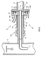
- the exhaust gas dilution device 1 comprises, as shown in Fig. 2 , an exhaust gas circulation pipe 101 for circulating the exhaust gas G , a mixing section 102 that is arranged in the exhaust gas circulation pipe 101 and that has an orifice 17, and a dilution gas supply pipe 14 that has an opening at the mixing section 102 and that supplies the dilution gas W to the exhaust gas circulation pipe 101.
- the exhaust gas circulation pipe 101 comprises the exhaust gas supply pipe 11 that supplies the exhaust gas G prior to dilution, an exhaust gas transport pipe 12 that circulates the exhaust gas G after dilution and a connecting member 13 that is arranged between the exhaust gas supply pipe 11 and the exhaust gas transport pipe 12.
- One side of the exhaust gas supply pipe 11 is inserted into and connected to a side wall of an exhaust pipe 5 for discharging the exhaust gas G of the engine E , and its exhaust gas introduce opening 111 opens toward a direction toward which the exhaust gas G flows. Then the exhaust gas G is supplied to the mixing section 102 at the other side of the exhaust gas supply pipe 11.
- An exhaust gas supply opening 112 that supplies the exhaust gas G to the mixing section 102 is arranged on the downstream side of the orifice 17, to be described later.
- a surrounding area of the exhaust gas supply pipe 11 is covered with a protection pipe 113 including a heat insulating layer so as to prevent the exhaust gas supply pipe 11 from being cooled by the ambient temperature.
- An outer diameter of the protection pipe 113 gradually decreases from the exhaust gas supply opening 112 by a predetermined length.
- the exhaust gas transport pipe 12 is to circulate the exhaust gas G diluted in the mixing section 102, and the filter 2, the vacuum pump 3 and the flowmeter 4 for catching the particulate matters in the exhaust gas G are arranged on the exhaust gas transport pipe 12.
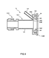
- the connecting member 13 is, as shown in Fig. 3 through Fig. 5 , to connect the exhaust gas supply pipe 11, the exhaust gas transport pipe 12 and the dilution gas supply pipe 14, and comprises a tubular section 131 to be fittingly inserted over an end part, having the exhaust gas supply opening 112, of the exhaust gas supply pipe 11 and a flange section 132 that is continuous to the tubular section 131 and to which the exhaust gas transport pipe 12 and the dilution gas supply pipe 14 are connected.
- the tubular section 131 comprises a small diameter section 1312 and a big diameter section 1311 whose inside diameter differs each other, and a tubular heat insulation member 133 is inserted into the big diameter section 1311 for insulating heat from the exhaust gas supply pipe 11 by the use of a circular plate 134 and a coil spring 135, to be described later. Then an inside diameter of the big diameter section 1311 becomes generally equal to that of the small diameter section 1312 in a state wherein the heat insulation member 133 is fittingly inserted into the big diameter section 1311, and an end part of the exhaust gas supply pipe 11 is inserted into the tubular section 131.
- the flange section 132 is formed on the downstream side of the tubular section 131 and is of a circular shape. A center part of the flange section 132 forms the mixing section 102, and at a side end face 132A of the tubular section 131, the dilution gas supply pipe 14, to be described later, is arranged spaced apart from the tubular section 131 and generally at right angle to the side end face 132A.
- the flange section 132 has a guide face 132C whose diameter gradually decreases toward the downstream at a front of the downstream side of the dilution gas supply opening 132B to make it easier for the dilution gas W that is supplied to the dilution gas supply pipe 14 to be mixed with the exhaust gas G .
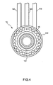
- a heat dissipation device for effectively dissipating the heat from the exhaust gas G in other words, multiple heat dissipating bores 15 that axially penetrate the flange section 132 are radially arranged at generally even intervals on the flange section 132.
- a concave section 16 is arranged on the downstream side end face 132D of the flange section 132 and the circular plate 134 having the orifice 17 shown in Fig. 6 is fittingly inserted into the concave section 16 and fixed by a screw 18. At this time, as shown in Fig.
- the circular plate 134 is mounted on the flange section 132 with an O-ring 162 fittingly inserted into a ring groove 161 arranged on the concave section 16 and with the heat insulation member 133 and the coil spring 135 placed between the big diameter section 1311 and the circular plate 134 so that the heat insulation member 133 is fittingly inserted into the big diameter section 1311 of the tubular body 131.
- the orifice 17 is formed perpendicular to a direction toward the exhaust gas G circulates.
- Through bores 1341 are arranged at even intervals on the circular plate 134 so as to coincide with some of the multiple heat dissipating bores 15 arranged on the flange section 132.
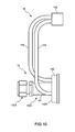
- the dilution gas supply pipe 14 comprises a main pipe 141, trifurcated pipes 142 connected to the main pipe 141 and dilution gas introduce pipes 143 each of which is connected to each of the trifurcated pipes 142 respectively.
- the dilution gas supply pipe 14 directly introduces the dilution gas W into the mixing section 102. Then as shown in Fig. 8 , openings of the mixing section 102 of the dilution gas supply pipe 14, in other words, dilution gas supply openings 132B, of the dilution gas introduce pipe 143, locating at the flange section 132 are arranged at a surrounding area of the exhaust gas circulation pipe 101 at even intervals.
- the dilution gas supply pipe 14 and the exhaust gas circulation pipe 101 are arranged spaced apart spatially, it is possible to prevent rise in the temperature of the dilution gas W due to an increased temperature of the exhaust gas circulation pipe 101 prior to mixing the exhaust gas G and the dilution gas W .
- the temperature of the exhaust gas G after dilution can be preferably controlled, thereby obtaining accurate measurement results.
- the heat dissipating bores 15, as being the heat dissipating device, are arranged on the connecting member 13, it is possible to preferably dissipate the heat from the exhaust gas G . As a result, influences on the dilution gas W from the temperature of the exhaust gas G can be further reduced.
- the present claimed invention is not limited to the above-mentioned embodiment.
- three dilution gas introduce pipes are arranged in the above-mentioned embodiment, however, it is not limited to this and two or four dilution gas introduce pipes may be arranged. At this time, it is preferable to arrange the dilution gas supply openings for each of the dilution gas supply pipes at even intervals.
- the dilution gas supply pipe is connected at generally right angle to the end face of the flange section in the above-mentioned embodiment, however, it is not limited to this and the dilution gas supply pipe may be arranged spaced apart from the exhaust gas supply pipe spatially and the dilution gas supply pipe, more specifically, the dilution gas introduce pipe may be connected to the exhaust gas supply pipe in a tilted state to a direction to which the exhaust gas circulates. With this arrangement, a flow of the dilution gas and the exhaust gas after dilution becomes smooth, thereby preventing the particulate matters from attaching to an inner face of the exhaust gas transport pipe.
- each length of the dilution gas supply pipes in other words, each length of the dilution gas introduce pipes may be made the same.
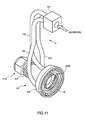
- the exhaust gas supply opening is arranged on the downstream side of the orifice in the above-mentioned embodiment, however, it may be arranged on an upstream side of the orifice as shown in Fig. 12 .
- the dilution gas supply pipe and the exhaust gas circulation pipe are arranged spaced apart spatially, it is possible to prevent rise in the temperature of the dilution gas due to the increased temperature of the exhaust gas circulation pipe prior to mixing the exhaust gas and the dilution gas.
- the temperature of the exhaust gas after dilution can be preferably controlled, thereby obtaining accurate measurement results.
Landscapes
- Health & Medical Sciences (AREA)
- Life Sciences & Earth Sciences (AREA)
- Engineering & Computer Science (AREA)
- Biomedical Technology (AREA)
- Molecular Biology (AREA)
- Physics & Mathematics (AREA)
- Chemical & Material Sciences (AREA)
- Analytical Chemistry (AREA)
- Biochemistry (AREA)
- General Health & Medical Sciences (AREA)
- General Physics & Mathematics (AREA)
- Immunology (AREA)
- Pathology (AREA)
- Sampling And Sample Adjustment (AREA)
Applications Claiming Priority (2)
| Application Number | Priority Date | Filing Date | Title |
|---|---|---|---|
| JP2005169085 | 2005-06-09 | ||
| PCT/JP2006/310221 WO2006132081A1 (ja) | 2005-06-09 | 2006-05-23 | 排ガス希釈装置 |
Publications (3)
| Publication Number | Publication Date |
|---|---|
| EP1890125A1 true EP1890125A1 (de) | 2008-02-20 |
| EP1890125A4 EP1890125A4 (de) | 2011-04-13 |
| EP1890125B1 EP1890125B1 (de) | 2018-11-28 |
Family
ID=37498285
Family Applications (1)
| Application Number | Title | Priority Date | Filing Date |
|---|---|---|---|
| EP06756477.3A Not-in-force EP1890125B1 (de) | 2005-06-09 | 2006-05-23 | Abgasverdünnungsvorrichtung |
Country Status (6)
| Country | Link |
|---|---|
| US (1) | US7717002B2 (de) |
| EP (1) | EP1890125B1 (de) |
| JP (1) | JP4827841B2 (de) |
| KR (1) | KR101320218B1 (de) |
| CN (1) | CN101194156B (de) |
| WO (1) | WO2006132081A1 (de) |
Cited By (2)
| Publication number | Priority date | Publication date | Assignee | Title |
|---|---|---|---|---|
| EP2172762A2 (de) | 2008-10-02 | 2010-04-07 | AVL List GmbH | Vorrichtung zur Verdünnung eines zu analysierenden Gases mit einem Verdünnungsgas |
| WO2019072437A1 (de) * | 2017-10-09 | 2019-04-18 | Bundesrepublik Deutschland, Vertreten Durch Das Bundesministerium Für Wirtschaft Und Energie, Dieses Vertreten Durch Den Präsidenten Der Physikalisch-Technischen Bundesanstalt | Aerosol-mischvorrichtung |
Families Citing this family (5)
| Publication number | Priority date | Publication date | Assignee | Title |
|---|---|---|---|---|
| US20100089180A1 (en) * | 2008-04-08 | 2010-04-15 | The Board Of Regents Of The Nevada System Of Higher Education, | Sampling device and method and system for its use |
| KR100949088B1 (ko) * | 2009-09-22 | 2010-03-23 | 웰빙그린(주) | 무늬 도장용 롤러 |
| CN102589939A (zh) * | 2012-03-16 | 2012-07-18 | 中国石油化工股份有限公司 | 硫磺制酸转化器二氧化硫测量取样方法 |
| JP5912981B2 (ja) * | 2012-08-06 | 2016-04-27 | 株式会社堀場製作所 | 排ガス希釈装置及びpm測定システム |
| US10030568B2 (en) | 2014-03-27 | 2018-07-24 | Dwight Eric STORY | Exhaust system integrity tester |
Family Cites Families (13)
| Publication number | Priority date | Publication date | Assignee | Title |
|---|---|---|---|---|
| US3933618A (en) * | 1974-03-11 | 1976-01-20 | Blue Ember Flame Corporation | Gas generation apparatuses and processes |
| JPS586903B2 (ja) * | 1975-03-28 | 1983-02-07 | 株式会社日立製作所 | ブンセキソウチヨウサンプリングソウチ |
| JPS56132545A (en) * | 1980-03-21 | 1981-10-16 | Nippon Soken Inc | Apparatus for measuring amount of exhausted fine particle |
| JPS586903A (ja) | 1981-07-07 | 1983-01-14 | Hitachi Cable Ltd | 海綿状銅材の製造方法 |
| JP3257850B2 (ja) * | 1993-02-25 | 2002-02-18 | 株式会社日立製作所 | 低圧気中微粒子サンプリングシステム及び微粒子計測システム並びに化学反応装置及びcvd装置及びエッチング装置 |
| JPH06265453A (ja) * | 1993-03-16 | 1994-09-22 | Fuji Electric Co Ltd | 自動車排ガスサンプリングプローブのプローブ接続用キャップ |
| JP3634037B2 (ja) * | 1995-11-24 | 2005-03-30 | 株式会社堀場製作所 | パーティキュレートの付着低減化を図った配管構造 |
| JP3607118B2 (ja) | 1999-05-21 | 2005-01-05 | 株式会社堀場製作所 | 排ガス希釈装置 |
| JP3670924B2 (ja) * | 2000-03-03 | 2005-07-13 | 株式会社堀場製作所 | 排ガス希釈装置 |
| US6481299B2 (en) * | 2001-03-23 | 2002-11-19 | Avl North America Inc. | Particulate sampling probe and dilution tunnel |
| JP3502060B2 (ja) * | 2001-05-11 | 2004-03-02 | 日野自動車株式会社 | スモークメータ |
| US6684719B2 (en) * | 2002-05-03 | 2004-02-03 | Caterpillar Inc | Method and apparatus for mixing gases |
| US7044009B2 (en) * | 2002-05-20 | 2006-05-16 | Caterpillar Inc. | Dilution tunnel |
-
2006
- 2006-05-23 KR KR1020077028676A patent/KR101320218B1/ko not_active Expired - Fee Related
- 2006-05-23 JP JP2007520052A patent/JP4827841B2/ja not_active Expired - Fee Related
- 2006-05-23 WO PCT/JP2006/310221 patent/WO2006132081A1/ja not_active Ceased
- 2006-05-23 EP EP06756477.3A patent/EP1890125B1/de not_active Not-in-force
- 2006-05-23 US US11/915,525 patent/US7717002B2/en active Active
- 2006-05-23 CN CN2006800202098A patent/CN101194156B/zh active Active
Cited By (3)
| Publication number | Priority date | Publication date | Assignee | Title |
|---|---|---|---|---|
| EP2172762A2 (de) | 2008-10-02 | 2010-04-07 | AVL List GmbH | Vorrichtung zur Verdünnung eines zu analysierenden Gases mit einem Verdünnungsgas |
| EP2172762A3 (de) * | 2008-10-02 | 2011-04-27 | AVL List GmbH | Vorrichtung zur Verdünnung eines zu analysierenden Gases mit einem Verdünnungsgas |
| WO2019072437A1 (de) * | 2017-10-09 | 2019-04-18 | Bundesrepublik Deutschland, Vertreten Durch Das Bundesministerium Für Wirtschaft Und Energie, Dieses Vertreten Durch Den Präsidenten Der Physikalisch-Technischen Bundesanstalt | Aerosol-mischvorrichtung |
Also Published As
| Publication number | Publication date |
|---|---|
| CN101194156A (zh) | 2008-06-04 |
| KR20080014837A (ko) | 2008-02-14 |
| US7717002B2 (en) | 2010-05-18 |
| KR101320218B1 (ko) | 2013-10-21 |
| JP4827841B2 (ja) | 2011-11-30 |
| CN101194156B (zh) | 2012-10-03 |
| JPWO2006132081A1 (ja) | 2009-01-08 |
| EP1890125B1 (de) | 2018-11-28 |
| EP1890125A4 (de) | 2011-04-13 |
| US20090084200A1 (en) | 2009-04-02 |
| WO2006132081A1 (ja) | 2006-12-14 |
Similar Documents
| Publication | Publication Date | Title |
|---|---|---|
| JP3583765B2 (ja) | パティキュレート・サンプラ及び移送管アセンブリ及び排出試験ユニット | |
| EP2866016A1 (de) | Abgasprobenahmevorrichtung und Abgasanalysesystem | |
| US6684719B2 (en) | Method and apparatus for mixing gases | |
| US6843104B2 (en) | Sampling system for exhaust gas sensors and method of using same | |
| US7717002B2 (en) | Exhaust gas dilution device | |
| US20100175459A1 (en) | Device for the determination of the concentration of solid particles | |
| JP2013533955A (ja) | 流体多点捕捉/分配装置、特に、ターボ機械吸気口の圧力タッピング用プローブ | |
| US9995720B2 (en) | Plug-in NOx sensor snorkel for reading optimization under packaging constraints | |
| CA2906598C (en) | Containment housing with integrated test aerosol injection and sampling | |
| WO2012146417A1 (de) | Sensorvorrichtung zur erfassung eines parameters eines strömenden fluiden mediums | |
| US9952124B2 (en) | System for taking exhaust gas samples from internal combustion engines | |
| EP3179227A1 (de) | Abgasverdünnungsvorrichtung und abgasmesssystem damit | |
| DE4133452A1 (de) | Vorrichtung zur dynamischen messung der partikeldichte in einer gasstroemung | |
| DE102020120593A1 (de) | Inline-Kompaktmessgerät | |
| US8584537B2 (en) | Extraction tube for emission measurement systems | |
| CN114965158A (zh) | 气幕机构及测量装置 | |
| DE102020131021A1 (de) | Vorrichtung für einen Gaschromatographen, insbesondere einen Temperaturgradienten-Gaschromatographen, sowie Gaschromatograph mit einer solchen Vorrichtung | |
| NL2021665B1 (en) | A mixer for an engine exhaust system | |
| DE19852390B4 (de) | Analysenvorrichtung umfassend einen Gaschromatographen mit einer Säule und einen Pyrolysator sowie Block hoher Wärmeleitfähigkeit | |
| CN106896078B (zh) | 一种柴油机尾气脱硝氨逃逸测试装置 | |
| CN114718710A (zh) | 传感器安装座、传感器组件以及排气系统 | |
| US20200292508A1 (en) | Column oven and chromatography | |
| US9506898B1 (en) | Device for controlled vapor generation | |
| JPH102767A (ja) | 流量計測装置 |
Legal Events
| Date | Code | Title | Description |
|---|---|---|---|
| PUAI | Public reference made under article 153(3) epc to a published international application that has entered the european phase |
Free format text: ORIGINAL CODE: 0009012 |
|
| 17P | Request for examination filed |
Effective date: 20071119 |
|
| AK | Designated contracting states |
Kind code of ref document: A1 Designated state(s): AT BE BG CH CY CZ DE DK EE ES FI FR GB GR HU IE IS IT LI LT LU LV MC NL PL PT RO SE SI SK TR |
|
| DAX | Request for extension of the european patent (deleted) | ||
| A4 | Supplementary search report drawn up and despatched |
Effective date: 20110310 |
|
| 17Q | First examination report despatched |
Effective date: 20110907 |
|
| STAA | Information on the status of an ep patent application or granted ep patent |
Free format text: STATUS: EXAMINATION IS IN PROGRESS |
|
| GRAP | Despatch of communication of intention to grant a patent |
Free format text: ORIGINAL CODE: EPIDOSNIGR1 |
|
| STAA | Information on the status of an ep patent application or granted ep patent |
Free format text: STATUS: GRANT OF PATENT IS INTENDED |
|
| RIC1 | Information provided on ipc code assigned before grant |
Ipc: G01N 1/22 20060101AFI20180509BHEP |
|
| INTG | Intention to grant announced |
Effective date: 20180613 |
|
| GRAS | Grant fee paid |
Free format text: ORIGINAL CODE: EPIDOSNIGR3 |
|
| GRAA | (expected) grant |
Free format text: ORIGINAL CODE: 0009210 |
|
| STAA | Information on the status of an ep patent application or granted ep patent |
Free format text: STATUS: THE PATENT HAS BEEN GRANTED |
|
| AK | Designated contracting states |
Kind code of ref document: B1 Designated state(s): AT BE BG CH CY CZ DE DK EE ES FI FR GB GR HU IE IS IT LI LT LU LV MC NL PL PT RO SE SI SK TR |
|
| REG | Reference to a national code |
Ref country code: GB Ref legal event code: FG4D |
|
| REG | Reference to a national code |
Ref country code: CH Ref legal event code: EP |
|
| REG | Reference to a national code |
Ref country code: AT Ref legal event code: REF Ref document number: 1070797 Country of ref document: AT Kind code of ref document: T Effective date: 20181215 |
|
| REG | Reference to a national code |
Ref country code: DE Ref legal event code: R096 Ref document number: 602006056948 Country of ref document: DE |
|
| REG | Reference to a national code |
Ref country code: IE Ref legal event code: FG4D |
|
| REG | Reference to a national code |
Ref country code: NL Ref legal event code: MP Effective date: 20181128 |
|
| REG | Reference to a national code |
Ref country code: LT Ref legal event code: MG4D |
|
| REG | Reference to a national code |
Ref country code: AT Ref legal event code: MK05 Ref document number: 1070797 Country of ref document: AT Kind code of ref document: T Effective date: 20181128 |
|
| PG25 | Lapsed in a contracting state [announced via postgrant information from national office to epo] |
Ref country code: IS Free format text: LAPSE BECAUSE OF FAILURE TO SUBMIT A TRANSLATION OF THE DESCRIPTION OR TO PAY THE FEE WITHIN THE PRESCRIBED TIME-LIMIT Effective date: 20190328 Ref country code: FI Free format text: LAPSE BECAUSE OF FAILURE TO SUBMIT A TRANSLATION OF THE DESCRIPTION OR TO PAY THE FEE WITHIN THE PRESCRIBED TIME-LIMIT Effective date: 20181128 Ref country code: AT Free format text: LAPSE BECAUSE OF FAILURE TO SUBMIT A TRANSLATION OF THE DESCRIPTION OR TO PAY THE FEE WITHIN THE PRESCRIBED TIME-LIMIT Effective date: 20181128 Ref country code: LT Free format text: LAPSE BECAUSE OF FAILURE TO SUBMIT A TRANSLATION OF THE DESCRIPTION OR TO PAY THE FEE WITHIN THE PRESCRIBED TIME-LIMIT Effective date: 20181128 Ref country code: LV Free format text: LAPSE BECAUSE OF FAILURE TO SUBMIT A TRANSLATION OF THE DESCRIPTION OR TO PAY THE FEE WITHIN THE PRESCRIBED TIME-LIMIT Effective date: 20181128 Ref country code: ES Free format text: LAPSE BECAUSE OF FAILURE TO SUBMIT A TRANSLATION OF THE DESCRIPTION OR TO PAY THE FEE WITHIN THE PRESCRIBED TIME-LIMIT Effective date: 20181128 Ref country code: BG Free format text: LAPSE BECAUSE OF FAILURE TO SUBMIT A TRANSLATION OF THE DESCRIPTION OR TO PAY THE FEE WITHIN THE PRESCRIBED TIME-LIMIT Effective date: 20190228 |
|
| PG25 | Lapsed in a contracting state [announced via postgrant information from national office to epo] |
Ref country code: SE Free format text: LAPSE BECAUSE OF FAILURE TO SUBMIT A TRANSLATION OF THE DESCRIPTION OR TO PAY THE FEE WITHIN THE PRESCRIBED TIME-LIMIT Effective date: 20181128 Ref country code: PT Free format text: LAPSE BECAUSE OF FAILURE TO SUBMIT A TRANSLATION OF THE DESCRIPTION OR TO PAY THE FEE WITHIN THE PRESCRIBED TIME-LIMIT Effective date: 20190328 Ref country code: GR Free format text: LAPSE BECAUSE OF FAILURE TO SUBMIT A TRANSLATION OF THE DESCRIPTION OR TO PAY THE FEE WITHIN THE PRESCRIBED TIME-LIMIT Effective date: 20190301 |
|
| PG25 | Lapsed in a contracting state [announced via postgrant information from national office to epo] |
Ref country code: NL Free format text: LAPSE BECAUSE OF FAILURE TO SUBMIT A TRANSLATION OF THE DESCRIPTION OR TO PAY THE FEE WITHIN THE PRESCRIBED TIME-LIMIT Effective date: 20181128 |
|
| PG25 | Lapsed in a contracting state [announced via postgrant information from national office to epo] |
Ref country code: CZ Free format text: LAPSE BECAUSE OF FAILURE TO SUBMIT A TRANSLATION OF THE DESCRIPTION OR TO PAY THE FEE WITHIN THE PRESCRIBED TIME-LIMIT Effective date: 20181128 Ref country code: PL Free format text: LAPSE BECAUSE OF FAILURE TO SUBMIT A TRANSLATION OF THE DESCRIPTION OR TO PAY THE FEE WITHIN THE PRESCRIBED TIME-LIMIT Effective date: 20181128 Ref country code: DK Free format text: LAPSE BECAUSE OF FAILURE TO SUBMIT A TRANSLATION OF THE DESCRIPTION OR TO PAY THE FEE WITHIN THE PRESCRIBED TIME-LIMIT Effective date: 20181128 Ref country code: IT Free format text: LAPSE BECAUSE OF FAILURE TO SUBMIT A TRANSLATION OF THE DESCRIPTION OR TO PAY THE FEE WITHIN THE PRESCRIBED TIME-LIMIT Effective date: 20181128 |
|
| REG | Reference to a national code |
Ref country code: DE Ref legal event code: R097 Ref document number: 602006056948 Country of ref document: DE |
|
| PG25 | Lapsed in a contracting state [announced via postgrant information from national office to epo] |
Ref country code: EE Free format text: LAPSE BECAUSE OF FAILURE TO SUBMIT A TRANSLATION OF THE DESCRIPTION OR TO PAY THE FEE WITHIN THE PRESCRIBED TIME-LIMIT Effective date: 20181128 Ref country code: RO Free format text: LAPSE BECAUSE OF FAILURE TO SUBMIT A TRANSLATION OF THE DESCRIPTION OR TO PAY THE FEE WITHIN THE PRESCRIBED TIME-LIMIT Effective date: 20181128 Ref country code: SK Free format text: LAPSE BECAUSE OF FAILURE TO SUBMIT A TRANSLATION OF THE DESCRIPTION OR TO PAY THE FEE WITHIN THE PRESCRIBED TIME-LIMIT Effective date: 20181128 |
|
| PLBE | No opposition filed within time limit |
Free format text: ORIGINAL CODE: 0009261 |
|
| STAA | Information on the status of an ep patent application or granted ep patent |
Free format text: STATUS: NO OPPOSITION FILED WITHIN TIME LIMIT |
|
| PG25 | Lapsed in a contracting state [announced via postgrant information from national office to epo] |
Ref country code: SI Free format text: LAPSE BECAUSE OF FAILURE TO SUBMIT A TRANSLATION OF THE DESCRIPTION OR TO PAY THE FEE WITHIN THE PRESCRIBED TIME-LIMIT Effective date: 20181128 |
|
| 26N | No opposition filed |
Effective date: 20190829 |
|
| REG | Reference to a national code |
Ref country code: CH Ref legal event code: PL |
|
| PG25 | Lapsed in a contracting state [announced via postgrant information from national office to epo] |
Ref country code: CH Free format text: LAPSE BECAUSE OF NON-PAYMENT OF DUE FEES Effective date: 20190531 Ref country code: LI Free format text: LAPSE BECAUSE OF NON-PAYMENT OF DUE FEES Effective date: 20190531 Ref country code: MC Free format text: LAPSE BECAUSE OF FAILURE TO SUBMIT A TRANSLATION OF THE DESCRIPTION OR TO PAY THE FEE WITHIN THE PRESCRIBED TIME-LIMIT Effective date: 20181128 |
|
| REG | Reference to a national code |
Ref country code: BE Ref legal event code: MM Effective date: 20190531 |
|
| PG25 | Lapsed in a contracting state [announced via postgrant information from national office to epo] |
Ref country code: LU Free format text: LAPSE BECAUSE OF NON-PAYMENT OF DUE FEES Effective date: 20190523 |
|
| PG25 | Lapsed in a contracting state [announced via postgrant information from national office to epo] |
Ref country code: TR Free format text: LAPSE BECAUSE OF FAILURE TO SUBMIT A TRANSLATION OF THE DESCRIPTION OR TO PAY THE FEE WITHIN THE PRESCRIBED TIME-LIMIT Effective date: 20181128 |
|
| PG25 | Lapsed in a contracting state [announced via postgrant information from national office to epo] |
Ref country code: IE Free format text: LAPSE BECAUSE OF NON-PAYMENT OF DUE FEES Effective date: 20190523 |
|
| PG25 | Lapsed in a contracting state [announced via postgrant information from national office to epo] |
Ref country code: BE Free format text: LAPSE BECAUSE OF NON-PAYMENT OF DUE FEES Effective date: 20190531 |
|
| PG25 | Lapsed in a contracting state [announced via postgrant information from national office to epo] |
Ref country code: CY Free format text: LAPSE BECAUSE OF FAILURE TO SUBMIT A TRANSLATION OF THE DESCRIPTION OR TO PAY THE FEE WITHIN THE PRESCRIBED TIME-LIMIT Effective date: 20181128 |
|
| PG25 | Lapsed in a contracting state [announced via postgrant information from national office to epo] |
Ref country code: HU Free format text: LAPSE BECAUSE OF FAILURE TO SUBMIT A TRANSLATION OF THE DESCRIPTION OR TO PAY THE FEE WITHIN THE PRESCRIBED TIME-LIMIT; INVALID AB INITIO Effective date: 20060523 |
|
| PGFP | Annual fee paid to national office [announced via postgrant information from national office to epo] |
Ref country code: DE Payment date: 20210427 Year of fee payment: 16 Ref country code: FR Payment date: 20210412 Year of fee payment: 16 |
|
| PGFP | Annual fee paid to national office [announced via postgrant information from national office to epo] |
Ref country code: GB Payment date: 20210429 Year of fee payment: 16 |
|
| REG | Reference to a national code |
Ref country code: DE Ref legal event code: R119 Ref document number: 602006056948 Country of ref document: DE |
|
| GBPC | Gb: european patent ceased through non-payment of renewal fee |
Effective date: 20220523 |
|
| PG25 | Lapsed in a contracting state [announced via postgrant information from national office to epo] |
Ref country code: FR Free format text: LAPSE BECAUSE OF NON-PAYMENT OF DUE FEES Effective date: 20220531 |
|
| PG25 | Lapsed in a contracting state [announced via postgrant information from national office to epo] |
Ref country code: GB Free format text: LAPSE BECAUSE OF NON-PAYMENT OF DUE FEES Effective date: 20220523 Ref country code: DE Free format text: LAPSE BECAUSE OF NON-PAYMENT OF DUE FEES Effective date: 20221201 |