EP1890140A1 - Procédé destiné à vérifier la structure d'une soudure - Google Patents
Procédé destiné à vérifier la structure d'une soudure Download PDFInfo
- Publication number
- EP1890140A1 EP1890140A1 EP06017048A EP06017048A EP1890140A1 EP 1890140 A1 EP1890140 A1 EP 1890140A1 EP 06017048 A EP06017048 A EP 06017048A EP 06017048 A EP06017048 A EP 06017048A EP 1890140 A1 EP1890140 A1 EP 1890140A1
- Authority
- EP
- European Patent Office
- Prior art keywords
- microstructure
- ultrasonic surface
- surface wave
- determining
- probes
- Prior art date
- Legal status (The legal status is an assumption and is not a legal conclusion. Google has not performed a legal analysis and makes no representation as to the accuracy of the status listed.)
- Withdrawn
Links
- 238000000034 method Methods 0.000 title claims abstract description 43
- 238000012360 testing method Methods 0.000 claims abstract description 36
- 239000000463 material Substances 0.000 claims abstract description 21
- 239000000523 sample Substances 0.000 claims description 41
- 230000010363 phase shift Effects 0.000 claims description 17
- 238000010897 surface acoustic wave method Methods 0.000 claims description 2
- 238000005259 measurement Methods 0.000 description 31
- 230000035515 penetration Effects 0.000 description 11
- 238000006073 displacement reaction Methods 0.000 description 7
- 230000008018 melting Effects 0.000 description 7
- 238000002844 melting Methods 0.000 description 7
- 230000001419 dependent effect Effects 0.000 description 5
- 238000011161 development Methods 0.000 description 4
- 230000018109 developmental process Effects 0.000 description 4
- 238000011156 evaluation Methods 0.000 description 4
- 238000012935 Averaging Methods 0.000 description 2
- 238000013459 approach Methods 0.000 description 2
- 238000012512 characterization method Methods 0.000 description 2
- 230000003247 decreasing effect Effects 0.000 description 2
- 230000007547 defect Effects 0.000 description 2
- 230000000694 effects Effects 0.000 description 2
- 238000000265 homogenisation Methods 0.000 description 2
- 239000011148 porous material Substances 0.000 description 2
- 238000002604 ultrasonography Methods 0.000 description 2
- 238000004458 analytical method Methods 0.000 description 1
- 238000000137 annealing Methods 0.000 description 1
- 238000004364 calculation method Methods 0.000 description 1
- 230000015556 catabolic process Effects 0.000 description 1
- 238000010835 comparative analysis Methods 0.000 description 1
- 230000000052 comparative effect Effects 0.000 description 1
- 238000006731 degradation reaction Methods 0.000 description 1
- 238000001514 detection method Methods 0.000 description 1
- 230000005484 gravity Effects 0.000 description 1
- 238000011835 investigation Methods 0.000 description 1
- 230000002427 irreversible effect Effects 0.000 description 1
- 230000007774 longterm Effects 0.000 description 1
- 239000002184 metal Substances 0.000 description 1
- 230000010355 oscillation Effects 0.000 description 1
- 230000000750 progressive effect Effects 0.000 description 1
- 238000011084 recovery Methods 0.000 description 1
- 238000000611 regression analysis Methods 0.000 description 1
- 238000007711 solidification Methods 0.000 description 1
- 230000008023 solidification Effects 0.000 description 1
- 230000036962 time dependent Effects 0.000 description 1
Images



Classifications
-
- G—PHYSICS
- G01—MEASURING; TESTING
- G01N—INVESTIGATING OR ANALYSING MATERIALS BY DETERMINING THEIR CHEMICAL OR PHYSICAL PROPERTIES
- G01N29/00—Investigating or analysing materials by the use of ultrasonic, sonic or infrasonic waves; Visualisation of the interior of objects by transmitting ultrasonic or sonic waves through the object
- G01N29/04—Analysing solids
- G01N29/07—Analysing solids by measuring propagation velocity or propagation time of acoustic waves
- G01N29/075—Analysing solids by measuring propagation velocity or propagation time of acoustic waves by measuring or comparing phase angle
-
- G—PHYSICS
- G01—MEASURING; TESTING
- G01N—INVESTIGATING OR ANALYSING MATERIALS BY DETERMINING THEIR CHEMICAL OR PHYSICAL PROPERTIES
- G01N29/00—Investigating or analysing materials by the use of ultrasonic, sonic or infrasonic waves; Visualisation of the interior of objects by transmitting ultrasonic or sonic waves through the object
- G01N29/22—Details, e.g. general constructional or apparatus details
- G01N29/26—Arrangements for orientation or scanning by relative movement of the head and the sensor
- G01N29/265—Arrangements for orientation or scanning by relative movement of the head and the sensor by moving the sensor relative to a stationary material
-
- G—PHYSICS
- G01—MEASURING; TESTING
- G01N—INVESTIGATING OR ANALYSING MATERIALS BY DETERMINING THEIR CHEMICAL OR PHYSICAL PROPERTIES
- G01N2291/00—Indexing codes associated with group G01N29/00
- G01N2291/04—Wave modes and trajectories
- G01N2291/042—Wave modes
- G01N2291/0423—Surface waves, e.g. Rayleigh waves, Love waves
-
- G—PHYSICS
- G01—MEASURING; TESTING
- G01N—INVESTIGATING OR ANALYSING MATERIALS BY DETERMINING THEIR CHEMICAL OR PHYSICAL PROPERTIES
- G01N2291/00—Indexing codes associated with group G01N29/00
- G01N2291/10—Number of transducers
- G01N2291/103—Number of transducers one emitter, two or more receivers
-
- G—PHYSICS
- G01—MEASURING; TESTING
- G01N—INVESTIGATING OR ANALYSING MATERIALS BY DETERMINING THEIR CHEMICAL OR PHYSICAL PROPERTIES
- G01N2291/00—Indexing codes associated with group G01N29/00
- G01N2291/26—Scanned objects
- G01N2291/267—Welds
- G01N2291/2675—Seam, butt welding
-
- G—PHYSICS
- G01—MEASURING; TESTING
- G01N—INVESTIGATING OR ANALYSING MATERIALS BY DETERMINING THEIR CHEMICAL OR PHYSICAL PROPERTIES
- G01N2291/00—Indexing codes associated with group G01N29/00
- G01N2291/26—Scanned objects
- G01N2291/269—Various geometry objects
- G01N2291/2693—Rotor or turbine parts
Definitions
- the invention relates to a method for testing the microstructure of a welded joint on an inner or from the outer surface of a component extending to deeper cross-sections damage, for example due to material creep.
- the method should be less labor-intensive and time-consuming and thus more cost-effective and reliable overall.
- a method with the following steps is used for testing the microstructure of a welded connection for internal damage: generating at least one ultrasonic surface wave by means of a first test head, receiving the at least one ultrasonic surface wave by means of a second test head, determining the acoustic properties, in particular the speed of sound in the microstructure of the welded joint based on the relation between generated and received ultrasonic surface wave, determining the degree of damage of the internal microstructure of the welded joint on the basis of the determined acoustic properties.
- the invention for testing the microstructure of a weld test probes are set, which allow a highly accurate measurement of the acoustic properties, in particular the speed of sound of ultrasonic waves.
- the ultrasonic waves are emitted from the surface into the depth of the welded joint and move in particular as ultrasonic waves of different penetration depth (Rayleigh surface wave) within the microstructure.
- the measurement of the acoustic Properties do not take place as conventionally usual with sound impulses, but with the help of a continuous surface wave.
- the method according to the invention also advantageously comprises the steps of determining the phase shift between the at least one transmitted and the at least one received ultrasonic surface wave and determining the acoustic properties, in particular the speed of sound, in the microstructure on the basis of the determined phase shift.
- broadband piezoelectric probes with a corresponding feed wedge which are fed by a function generator with a sinusoidal voltage signal, are preferably used.
- the transmit signal as well as a pre-amplified receive signal are simultaneously applied to separate channels of an oscilloscope, whereby the phase shift between the two signals can be determined.
- the two probes are preferably moved relative to one another.
- This movement of the probes can be carried out by means of mechanized manipulators, which in particular comprise a high-precision displacement measuring system. In this way, a backlash-free and exactly reproducible displacement of the two probes is possible.
- mechanized manipulators which in particular comprise a high-precision displacement measuring system.
- the phase shift of the above-mentioned oscillations of transmitter and receiver signal changes relative to each other.
- the phase angle can be determined not only by moving the probes, but also electronically, in particular through the use of a High-frequency comparator circuit. This eliminates any manipulation of the probes and also the distance measuring system can be omitted.
- a change in the phase shift by a complete phase revolution of 2 ⁇ corresponds to a travel path of exactly one wavelength.
- the probes are particularly preferably moved relative to one another over a distance of the length of a plurality of wavelengths, and the average wavelength of the ultrasonic surface wave in the microstructure is calculated therefrom.
- the following steps are further provided: changing the frequency of the at least one transmitted ultrasonic surface wave and determining the acoustic properties in the microstructure on the basis of the gradient of the corresponding change in wavelength at least one received ultrasonic surface wave.
- the necessary conclusions about damage to the welded joint can be drawn across the associated material cross section.
- the absolute height of the speed of sound and, secondly, the gradient of the speed profile serve as evaluation criteria. It is also possible to perform relative measurements. The change of the phase position is evaluated at a constant test frequency over the weld cross section. In addition, comparative measurements can be made on less stressed parts of the same component.
- FIG. 1 illustrates a cross-section of a component 10 on which a first weld seam 12 and a second weld seam 14 are located.
- a method for testing the microstructure for internal damage in particular for creep damage, such as due to material creep.
- an ultrasonic surface wave is generated on a surface 16 of the component 10 in a test head, not shown in Fig. 1, which is received or recorded by means of a second test head, also not shown in FIG.
- From a comparison of the received ultrasonic surface wave with the transmitted ultrasonic surface wave and a speed of sound calculated therefrom in the microstructure of the component 10 can, as explained in more detail below, the degree of damage of the microstructure are determined.
- the method allows a depth-dependent testing of time-stressed or time-standing damaged welded joints. This test is possible even at a usually found in welded joints inhomogeneous structure structure with high local and depth-dependent differences in the material properties.
- the method ensures that the result is based purely on physical quantities and objectively collected.
- the absolute level of the speed of sound in the microstructure of the component 10 can be changed by changing the frequency of the transmitted ultrasonic surface waves whose penetration depth. With these so-called Rayleigh waves, a depth profile of the speed of sound in the microstructure of the component 10 can then be created. Through targeted integral detection of the acoustic properties at different penetration depths, a sonic velocity profile can be created with the ultrasonic surface waves in this way, the course of which is sensitively influenced by progress of damage to the component 10. This represents a significant gain in knowledge, especially in the assessment of cemetery damage.
- FIG. 1 illustrates that, assuming a maximum pore concentration at the surface 16, an ultrasound surface wave 18 of low penetration first penetrates only a region 20 of the most damaged microstructure. Assuming a steady assumption of the damage with the depth of the component 10, the less damaged material fraction integrally detected by the ultrasonic surface wave 18 increases in proportion as the penetration depth increases (see FIG. 1).
- a minimum velocity of sound is measured as the location of the greatest damage. while an increase in the speed of sound is due to the decreasing pore concentration with increasing penetration depth.
- a variation of a frequency f from f 1 to f 2 is illustrated, which lies in a range from 400 kHz to 3 MHz.
- the wavelength of the associated ultrasonic surface wave ⁇ changes from a value ⁇ 1 to a value of ⁇ 2 with penetration depths of approximately 1 mm to approximately 8 mm.
- Fig. 2 it is illustrated that a near-surface creep damage thus leads to significantly different speed of sound between the surface 16 and a lower portion of the component 10 (see curve 22), while at a damage-free or undamaged material a nearly depth-constant course (see trace 24) is observed. From the curvature behavior of the measurement curves 22 and 24 or their curve gradient can thus be concluded that the damage progress in relation to the surface 16 as a reference region.
- frequencies are selected, resulting in a number of layers or support points which describe the course of the speed of sound in relation to the distance to the surface 16.
- frequencies between about 400 kHz to about 3 MHz are selected, resulting in a penetration depth of up to 8 mm for the materials usually to be examined. The measuring depth with the method of this kind is therefore considerable.
- the equation fulfills the requirements for a mathematical description model in a largely optimal way.
- two characteristic quantities are sufficient for the description of all measured curves, namely the specification of a surface sound velocity c 0 and of a gradient coefficient K.
- the integral sound velocity at any point in the interior of the component can be calculated from the known curve.
- this approach to welded joints or the welds 12 and 14 shown in Fig. 1 so measured and calculated sound velocities in deeper microstructures can be compared.
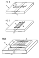
- FIGS. 4 to 6 illustrate the spatial procedure in the method according to the invention for testing the microstructure of a weld seam 12 on a component 10.
- a so-called coarse scanning (FIG. 4) is carried out for an overview evaluation, individual measuring tracks 26 being transverse to the longitudinal extent of the weld seam 12 are directed. These measuring tracks 26 represent the path between two test heads (illustrated below in FIGS. 7 to 9), which are moved individually or optionally together along these measuring tracks 26.
- FIG. 4 With the coarse scanning illustrated in FIG. 4, defects in the microstructure of the weld 12 as well as the immediately surrounding component are detected.
- so-called fine scanning illustrated in FIG. 5, individual measuring tracks 26 are subsequently aligned parallel to the longitudinal extent of the weld seam 12.
- FIG. 6 again illustrates that, according to the procedure according to the invention, a complete characterization of a weld 12 in its spatial extent is possible, this spatial extent being the length of the measurement tracks 26, the number and the spacing of the individual measurements and the penetration depth of the ultrasound Surface waves.
- FIG. 7 illustrates a first exemplary embodiment of a measurement setup 28 for carrying out the method according to the invention. It is a first, acting as a transmitter for ultrasonic surface wave probe 30 and a second, acting as a receiver of the ultrasonic surface waves probe head 32 is provided.
- the two probes 30 and 32 are arranged on a manipulator 34, by means of which a virtually backlash-free and exactly reproducible displacement of the two probes 30 and 32 on the component 10 to be tested along a straight line is ensured.
- the relative Traversing position of the two probes 30 and 32 is recorded via a high-precision displacement measuring system 36.
- the acting as a transmitter probe 30, which is designed as a broadband piezoelectric probe with a corresponding Vorlaufkeil is fed by a function generator 38 with a sinusoidal voltage signal and thereby generates a continuous ultrasonic surface wave.
- This ultrasonic surface wave propagates on the surface 16 of the component 10 along an axis of the test head 30 and is received by the test head 32 arranged in the opposite direction.
- the transmitter signal as well as the preamplified signal received by the probe 32 are simultaneously applied to separate channels of an oscilloscope 40, whereby a phase shift between the two signals can be determined.
- the displacement during a measuring operation is approximately 50 mm to approximately 100 mm, depending on the dimensions of the component 10 to be tested and the size of the probes 30 and 32 used, the change in the phase shift being recorded as a function of the measuring length.
- the thus determined data allow due to taking into account the number of swept phase shifts and the length of the measuring section, the calculation of a mean wavelength of the ultrasonic surface wave in the component 10.
- the speed of sound c in the component 10 is then based on the wavelength ⁇ and the frequency f, which by the frequency generator 38 is predetermined, calculated. By averaging the wavelength over the travel of the probes 30 and 32 in this way a very high measurement accuracy can be achieved.
- the above-explained coarse scanning (FIG. 4) makes it possible to detect defects within a short time, with conspicuous measuring points subsequently being subjected to a detailed fine scanning (FIG. 5) in a refined testing process (using a plurality of measurement frequencies).
- an alternative embodiment of a measurement setup 28 is illustrated in which two probes 30 and 32 are each arranged in a fixed probe array. These probes 30 and 32 are each connected to a function generator 38 and an oscilloscope 40 again.
- a displacement of the probes 30 and 32 by means of a manipulator is not provided here, but the probes 30 and 32 are arranged stationary and the measuring frequency is varied as a variable variable. Due to this procedure, the costs for the manipulator and the displacement measuring system are eliminated.
- the measurement can also be fully automatic.
- the arrangement according to FIG. 8 can also be used to evaluate a change in the phase angle between the two signals relative to a reference variable (eg base material) at constant probe spacing.
- a reference variable eg base material
- the rigid arrangement of the probes 30 and 32 is moved across the weld and evaluated the local changes in the phase position in response to material changes. This can be done electronically (Comparator circuit). The frequency range and thus the depth effect of the method remain unaffected.
- FIG. 9 illustrates an embodiment of a measurement setup 28 in which a total of three stationary probes 30, 32 and 42 are provided, of which the test head 30 is connected to a function generator 38 and the probes 32 and 42 are connected to an oscilloscope 40 as a receiver ,
- the signals of the two acting as a receiver probes 32 and 42 are adjusted to the phase equality.
- the precision of the measurement can be further increased, since in a head-to-head arrangement of metrologically relevant probe head could vary by a variable with the measurement frequency exit point from the supply wedge of the associated test head, but this by the presently provided comparable conditions for the Signal recording at the two acting as a receiver probes 32 and 42 can be bypassed with identical orientation.
- FIG. 10 illustrates an evaluation of progressions of the speed of sound over the cross section of one of the weld seams 12 or 14.
- FIG. 10 illustrates that a description of the damage state of the microstructure on a weld seam is possible by the sound velocity profile.
- Fig. 10 shows a total of four curves 44, 46, 48 and 50, each of which illustrate the course of the gradient of the speed of sound over a position transverse to a longitudinal extent of a weld.
- the line 44 shows a weld in new condition
- the line 46 an operationally stressed weld
- the line 48 an advanced operationally stressed weld
- line 50 finally, a weld with damaged microstructure.
- the line 44 basically has an M-shape, which extends with its two maxima in the region of melting lines 52 and 54, respectively. These melting lines form the respective Boundary region between one side of the weld and the adjacent component.
- the basically M-shaped line 44 thus flattens out over the increasing service life of the associated component (see lines 46 and 48 in FIG. 10).
- this change of the gradient K from an M-shape in the new state via a flattening in the operational state to a W-shape in the damaged state clearly the qualitative development course at the associated Weld seam shows.
- the microstructure In the initial state of a weld, the microstructure has a very inhomogeneous distribution, in particular in the area of the melting lines (solidification structure) different states. This manifests itself within the measurement curves or lines 44 to 50 by locally limited to these areas gradient coefficient K high degree. If a leveling in the course of the gradient coefficient K over the weld cross-section is to be determined, the metrological proof of a long-term operating stress at a high temperature level is carried out. Namely, such a stress leads via a so-called recovery annealing to the progressive degradation of these local inhomogeneities and thus to smaller differences in the acoustic properties within the weld seam. Such a development has been repeatedly confirmed in time-stressed pipe elbows and is expressed there by an increase in the speed of sound during this "homogenization phase", until a decrease in the absolute values of the speed of sound c is finally observed when irreversible damage occurs.
Landscapes
- Physics & Mathematics (AREA)
- Health & Medical Sciences (AREA)
- Life Sciences & Earth Sciences (AREA)
- Chemical & Material Sciences (AREA)
- Analytical Chemistry (AREA)
- Biochemistry (AREA)
- General Health & Medical Sciences (AREA)
- General Physics & Mathematics (AREA)
- Immunology (AREA)
- Pathology (AREA)
- Acoustics & Sound (AREA)
- Investigating Or Analyzing Materials By The Use Of Ultrasonic Waves (AREA)
Priority Applications (5)
| Application Number | Priority Date | Filing Date | Title |
|---|---|---|---|
| EP06017048A EP1890140A1 (fr) | 2006-08-16 | 2006-08-16 | Procédé destiné à vérifier la structure d'une soudure |
| PCT/EP2007/058003 WO2008019948A1 (fr) | 2006-08-16 | 2007-08-02 | Procédé pour le contrôle de la structure d'un assemblage par soudure |
| US12/310,145 US20090320598A1 (en) | 2006-08-16 | 2007-08-02 | Method for testing the microstructure of a welded joint |
| JP2009524161A JP2010500591A (ja) | 2006-08-16 | 2007-08-02 | 溶接継手の微細構造の検査方法 |
| EP07802466A EP2052246A1 (fr) | 2006-08-16 | 2007-08-02 | Procede pour le controle de la structure d'un assemblage par soudure |
Applications Claiming Priority (1)
| Application Number | Priority Date | Filing Date | Title |
|---|---|---|---|
| EP06017048A EP1890140A1 (fr) | 2006-08-16 | 2006-08-16 | Procédé destiné à vérifier la structure d'une soudure |
Publications (1)
| Publication Number | Publication Date |
|---|---|
| EP1890140A1 true EP1890140A1 (fr) | 2008-02-20 |
Family
ID=37814676
Family Applications (2)
| Application Number | Title | Priority Date | Filing Date |
|---|---|---|---|
| EP06017048A Withdrawn EP1890140A1 (fr) | 2006-08-16 | 2006-08-16 | Procédé destiné à vérifier la structure d'une soudure |
| EP07802466A Withdrawn EP2052246A1 (fr) | 2006-08-16 | 2007-08-02 | Procede pour le controle de la structure d'un assemblage par soudure |
Family Applications After (1)
| Application Number | Title | Priority Date | Filing Date |
|---|---|---|---|
| EP07802466A Withdrawn EP2052246A1 (fr) | 2006-08-16 | 2007-08-02 | Procede pour le controle de la structure d'un assemblage par soudure |
Country Status (4)
| Country | Link |
|---|---|
| US (1) | US20090320598A1 (fr) |
| EP (2) | EP1890140A1 (fr) |
| JP (1) | JP2010500591A (fr) |
| WO (1) | WO2008019948A1 (fr) |
Cited By (2)
| Publication number | Priority date | Publication date | Assignee | Title |
|---|---|---|---|---|
| CN106093203A (zh) * | 2016-08-25 | 2016-11-09 | 杨振峰 | 一种焊接表面及近表面裂纹深度检测装置 |
| DE102015114855A1 (de) * | 2015-09-04 | 2017-03-09 | Dr. Ing. H.C. F. Porsche Aktiengesellschaft | Verfahren zur Erfassung von Schädigungen eines Kunststoff-Metall- oder Metall-Metall-Verbundbauteils |
Families Citing this family (5)
| Publication number | Priority date | Publication date | Assignee | Title |
|---|---|---|---|---|
| US9063059B2 (en) | 2011-05-10 | 2015-06-23 | Edison Welding Institute, Inc. | Three-dimensional matrix phased array spot weld inspection system |
| US10598636B2 (en) * | 2015-12-31 | 2020-03-24 | VeriPhase, Inc. | Ultrasonic weld analysis for orthotropic steel decking systems in bridges |
| US10636064B2 (en) * | 2015-12-31 | 2020-04-28 | VeriPhase, Inc. | Method for monetization of the data processing of ultrasonic scan data files |
| US10126273B2 (en) * | 2016-02-29 | 2018-11-13 | The Boeing Company | Inspection of structures |
| CN113189205B (zh) * | 2021-03-23 | 2022-11-08 | 国能锅炉压力容器检验有限公司 | 一种超声导波检测在役主汽管道蠕变损伤的方法 |
Citations (5)
| Publication number | Priority date | Publication date | Assignee | Title |
|---|---|---|---|---|
| US4372163A (en) * | 1981-02-03 | 1983-02-08 | Rockwell International Corporation | Acoustic measurement of near surface property gradients |
| US4545249A (en) * | 1983-09-06 | 1985-10-08 | Trw Inc. | Acoustical position gage |
| DE4116584A1 (de) * | 1991-05-22 | 1992-11-26 | Nukem Gmbh | Verfahren und vorrichtung zur zerstoerungsfreien feststellung von werkstoffkennwerten |
| DE19640859A1 (de) * | 1996-10-03 | 1998-04-09 | Schmitt Thomas Karlheinz G Pro | Verfahren und Vorrichtung zur zerstörungsfreien Feststellung des Werkstoffzustands in Bauteilen |
| US20050132809A1 (en) * | 2002-02-06 | 2005-06-23 | Applied Metrics, Inc. | Methods for ultrasonic inspection of spot and seam resistance welds in metallic sheets and a spot weld examination probe system (SWEPS) |
Family Cites Families (4)
| Publication number | Priority date | Publication date | Assignee | Title |
|---|---|---|---|---|
| FR2551874B1 (fr) * | 1983-09-09 | 1986-04-18 | Electricite De France | Procede et dispositif de controle d'une piece metallique par ultrasons |
| US5894092A (en) * | 1996-09-27 | 1999-04-13 | Industrial Quality, Inc. | Method and system for obtaining near-surface characteristics of materials using ultrasonic Rayleigh waves |
| JP2001021542A (ja) * | 1999-07-07 | 2001-01-26 | Osaka Gas Co Ltd | 溶接線横割れ欠陥長さ測定方法 |
| JP3652943B2 (ja) * | 1999-11-29 | 2005-05-25 | 三菱重工業株式会社 | 金属材料の損傷評価方法及び装置 |
-
2006
- 2006-08-16 EP EP06017048A patent/EP1890140A1/fr not_active Withdrawn
-
2007
- 2007-08-02 US US12/310,145 patent/US20090320598A1/en not_active Abandoned
- 2007-08-02 WO PCT/EP2007/058003 patent/WO2008019948A1/fr not_active Ceased
- 2007-08-02 JP JP2009524161A patent/JP2010500591A/ja not_active Abandoned
- 2007-08-02 EP EP07802466A patent/EP2052246A1/fr not_active Withdrawn
Patent Citations (5)
| Publication number | Priority date | Publication date | Assignee | Title |
|---|---|---|---|---|
| US4372163A (en) * | 1981-02-03 | 1983-02-08 | Rockwell International Corporation | Acoustic measurement of near surface property gradients |
| US4545249A (en) * | 1983-09-06 | 1985-10-08 | Trw Inc. | Acoustical position gage |
| DE4116584A1 (de) * | 1991-05-22 | 1992-11-26 | Nukem Gmbh | Verfahren und vorrichtung zur zerstoerungsfreien feststellung von werkstoffkennwerten |
| DE19640859A1 (de) * | 1996-10-03 | 1998-04-09 | Schmitt Thomas Karlheinz G Pro | Verfahren und Vorrichtung zur zerstörungsfreien Feststellung des Werkstoffzustands in Bauteilen |
| US20050132809A1 (en) * | 2002-02-06 | 2005-06-23 | Applied Metrics, Inc. | Methods for ultrasonic inspection of spot and seam resistance welds in metallic sheets and a spot weld examination probe system (SWEPS) |
Cited By (3)
| Publication number | Priority date | Publication date | Assignee | Title |
|---|---|---|---|---|
| DE102015114855A1 (de) * | 2015-09-04 | 2017-03-09 | Dr. Ing. H.C. F. Porsche Aktiengesellschaft | Verfahren zur Erfassung von Schädigungen eines Kunststoff-Metall- oder Metall-Metall-Verbundbauteils |
| CN106093203A (zh) * | 2016-08-25 | 2016-11-09 | 杨振峰 | 一种焊接表面及近表面裂纹深度检测装置 |
| CN106093203B (zh) * | 2016-08-25 | 2018-10-12 | 杨振峰 | 一种焊接表面及近表面裂纹深度检测装置 |
Also Published As
| Publication number | Publication date |
|---|---|
| JP2010500591A (ja) | 2010-01-07 |
| US20090320598A1 (en) | 2009-12-31 |
| WO2008019948A1 (fr) | 2008-02-21 |
| EP2052246A1 (fr) | 2009-04-29 |
Similar Documents
| Publication | Publication Date | Title |
|---|---|---|
| EP2747934B1 (fr) | Procédé et dispositif destinés à la fabrication générative d'une pièce | |
| EP2052246A1 (fr) | Procede pour le controle de la structure d'un assemblage par soudure | |
| DE102008027228B4 (de) | Verfahren und Vorrichtung zur zerstörungsfreien Ultraschalluntersuchung eines Prüfstücks mit zueinander gewinkelten, ebenen Oberflächen | |
| WO2011138027A1 (fr) | Procédé et dispositif pour une analyse non destructive de matériaux par ultrasons | |
| EP0160922B1 (fr) | Procédé pour le contrôle ultrasonore non destructif d'objets ou de pièces et appareil pour l'exécution de ce procédé | |
| EP0217783A2 (fr) | Procédé pour la détection à l'aide d'ultrason de défauts du type en point et étendus isolés dans des pièces d'usinage | |
| DE102012112121B4 (de) | Verfahren und Vorrichtung zur zerstörungsfreien Prüfung eines rotationssymmetrischen Werkstücks, welches Abschnitte verschiedener Durchmesser aufweist | |
| DE102015211557B4 (de) | Vorrichtung und Verfahren zur mechanischen oder thermomechanischen und überlagerten thermischen Belastung metallischer Prüfkörper | |
| DE102004030381B3 (de) | Verfahren zur Online-Qualitätsprüfung beim Reibrührschweißen | |
| DE102016224988A1 (de) | Verfahren und Vorrichtung zum Nachweis von Defekten in einem Objekt | |
| DE102009038746B3 (de) | Verfahren und Vorrichtung zur Qualitätsprüfung eines umgeformten thermoplastischen faserverstärkten Kunststoffbauteils | |
| DE2613799C2 (de) | Verfahren zum Einrichten von Ultraschall-Prüfanlagen | |
| EP2609421B1 (fr) | Réglage automatique de l'angle d'incidence d'une tête de contrôle à ultrasons, en fonction de sa position | |
| DE19640859B4 (de) | Verfahren und Vorrichtung zur zerstörungsfreien Feststellung des Werkstoffzustands in Bauteilen | |
| WO2006074938A1 (fr) | Procede et dispositif de thermographie destines a determiner l'etat d'endommagement d'un composant | |
| DE102012110811A1 (de) | Prüfvorrichtung zur Beurteilung des Ermüdungsverhaltens eines Prüflings | |
| DE102012112120B4 (de) | Verfahren und Vorrichtung zur oberflächennahen zerstörungsfreien Prüfung eines rotationssymmetrischen Werkstücks mit abschnittsweise wechselndem Durchmesser mittels Ultraschall | |
| DE4116584A1 (de) | Verfahren und vorrichtung zur zerstoerungsfreien feststellung von werkstoffkennwerten | |
| EP3781938B1 (fr) | Dispositif et procédé de détermination de l'extension d'endroits défectueux par sondage acoustique v | |
| DE102006040869B4 (de) | Verfahren und Vorrichtung zur Detektierung eines Fehlers in einem schichtartigen nichtmetallischen Prüfling | |
| DE102021103803A1 (de) | Vorrichtung und Verfahren zur Erfassung materialinterner mechanischer Zustände eines Werkstücks | |
| EP1690084A1 (fr) | Procede, dispositif et eprouvette pour tester un element structurel, ainsi qu'utilisation du procede et du dispositif | |
| EP2689243B1 (fr) | Dispositif et procédé destinés au contrôle par ultrasons d'une pièce usinée | |
| DE102015114855A1 (de) | Verfahren zur Erfassung von Schädigungen eines Kunststoff-Metall- oder Metall-Metall-Verbundbauteils | |
| DE102019116142A1 (de) | Vorrichtung zur tomografischen Ultraschallprüfung einer Innenstruktur einer Metallbramme und Verfahren zur in-situ Qualitätsprüfung von Metallbrammen |
Legal Events
| Date | Code | Title | Description |
|---|---|---|---|
| PUAI | Public reference made under article 153(3) epc to a published international application that has entered the european phase |
Free format text: ORIGINAL CODE: 0009012 |
|
| AK | Designated contracting states |
Kind code of ref document: A1 Designated state(s): AT BE BG CH CY CZ DE DK EE ES FI FR GB GR HU IE IS IT LI LT LU LV MC NL PL PT RO SE SI SK TR |
|
| AX | Request for extension of the european patent |
Extension state: AL BA HR MK YU |
|
| AKX | Designation fees paid | ||
| STAA | Information on the status of an ep patent application or granted ep patent |
Free format text: STATUS: THE APPLICATION IS DEEMED TO BE WITHDRAWN |
|
| 18D | Application deemed to be withdrawn |
Effective date: 20080821 |
|
| REG | Reference to a national code |
Ref country code: DE Ref legal event code: 8566 |