EP1890168A1 - Scanner à laser - Google Patents
Scanner à laser Download PDFInfo
- Publication number
- EP1890168A1 EP1890168A1 EP06119147A EP06119147A EP1890168A1 EP 1890168 A1 EP1890168 A1 EP 1890168A1 EP 06119147 A EP06119147 A EP 06119147A EP 06119147 A EP06119147 A EP 06119147A EP 1890168 A1 EP1890168 A1 EP 1890168A1
- Authority
- EP
- European Patent Office
- Prior art keywords
- light
- laser
- rotary body
- rotor
- laser scanner
- Prior art date
- Legal status (The legal status is an assumption and is not a legal conclusion. Google has not performed a legal analysis and makes no representation as to the accuracy of the status listed.)
- Withdrawn
Links
- 230000003287 optical effect Effects 0.000 claims abstract description 50
- 230000005540 biological transmission Effects 0.000 claims description 16
- 238000011156 evaluation Methods 0.000 claims description 13
- 230000008878 coupling Effects 0.000 claims description 3
- 238000010168 coupling process Methods 0.000 claims description 3
- 238000005859 coupling reaction Methods 0.000 claims description 3
- 239000006096 absorbing agent Substances 0.000 claims description 2
- 210000001747 pupil Anatomy 0.000 claims description 2
- 239000000835 fiber Substances 0.000 description 13
- 238000013461 design Methods 0.000 description 6
- 210000003128 head Anatomy 0.000 description 5
- 238000005259 measurement Methods 0.000 description 5
- 239000013307 optical fiber Substances 0.000 description 3
- 230000001419 dependent effect Effects 0.000 description 2
- 230000007613 environmental effect Effects 0.000 description 2
- 238000002310 reflectometry Methods 0.000 description 2
- 230000035945 sensitivity Effects 0.000 description 2
- BJQHLKABXJIVAM-UHFFFAOYSA-N bis(2-ethylhexyl) phthalate Chemical compound CCCCC(CC)COC(=O)C1=CC=CC=C1C(=O)OCC(CC)CCCC BJQHLKABXJIVAM-UHFFFAOYSA-N 0.000 description 1
- 239000011248 coating agent Substances 0.000 description 1
- 238000000576 coating method Methods 0.000 description 1
- 238000004891 communication Methods 0.000 description 1
- 238000007599 discharging Methods 0.000 description 1
- 239000000428 dust Substances 0.000 description 1
- 230000000694 effects Effects 0.000 description 1
- 238000005516 engineering process Methods 0.000 description 1
- 239000011521 glass Substances 0.000 description 1
- 238000003384 imaging method Methods 0.000 description 1
- 230000002452 interceptive effect Effects 0.000 description 1
- 238000000034 method Methods 0.000 description 1
- 230000005693 optoelectronics Effects 0.000 description 1
- 238000007493 shaping process Methods 0.000 description 1
- 230000008054 signal transmission Effects 0.000 description 1
- 230000003595 spectral effect Effects 0.000 description 1
- 230000001629 suppression Effects 0.000 description 1
- 238000012360 testing method Methods 0.000 description 1
- 238000011179 visual inspection Methods 0.000 description 1
Images



Classifications
-
- G—PHYSICS
- G01—MEASURING; TESTING
- G01S—RADIO DIRECTION-FINDING; RADIO NAVIGATION; DETERMINING DISTANCE OR VELOCITY BY USE OF RADIO WAVES; LOCATING OR PRESENCE-DETECTING BY USE OF THE REFLECTION OR RERADIATION OF RADIO WAVES; ANALOGOUS ARRANGEMENTS USING OTHER WAVES
- G01S17/00—Systems using the reflection or reradiation of electromagnetic waves other than radio waves, e.g. lidar systems
- G01S17/02—Systems using the reflection of electromagnetic waves other than radio waves
- G01S17/06—Systems determining position data of a target
- G01S17/42—Simultaneous measurement of distance and other co-ordinates
-
- G—PHYSICS
- G01—MEASURING; TESTING
- G01S—RADIO DIRECTION-FINDING; RADIO NAVIGATION; DETERMINING DISTANCE OR VELOCITY BY USE OF RADIO WAVES; LOCATING OR PRESENCE-DETECTING BY USE OF THE REFLECTION OR RERADIATION OF RADIO WAVES; ANALOGOUS ARRANGEMENTS USING OTHER WAVES
- G01S17/00—Systems using the reflection or reradiation of electromagnetic waves other than radio waves, e.g. lidar systems
- G01S17/88—Lidar systems specially adapted for specific applications
- G01S17/89—Lidar systems specially adapted for specific applications for mapping or imaging
-
- G—PHYSICS
- G01—MEASURING; TESTING
- G01S—RADIO DIRECTION-FINDING; RADIO NAVIGATION; DETERMINING DISTANCE OR VELOCITY BY USE OF RADIO WAVES; LOCATING OR PRESENCE-DETECTING BY USE OF THE REFLECTION OR RERADIATION OF RADIO WAVES; ANALOGOUS ARRANGEMENTS USING OTHER WAVES
- G01S7/00—Details of systems according to groups G01S13/00, G01S15/00, G01S17/00
- G01S7/48—Details of systems according to groups G01S13/00, G01S15/00, G01S17/00 of systems according to group G01S17/00
- G01S7/481—Constructional features, e.g. arrangements of optical elements
- G01S7/4817—Constructional features, e.g. arrangements of optical elements relating to scanning
-
- G—PHYSICS
- G01—MEASURING; TESTING
- G01S—RADIO DIRECTION-FINDING; RADIO NAVIGATION; DETERMINING DISTANCE OR VELOCITY BY USE OF RADIO WAVES; LOCATING OR PRESENCE-DETECTING BY USE OF THE REFLECTION OR RERADIATION OF RADIO WAVES; ANALOGOUS ARRANGEMENTS USING OTHER WAVES
- G01S7/00—Details of systems according to groups G01S13/00, G01S15/00, G01S17/00
- G01S7/48—Details of systems according to groups G01S13/00, G01S15/00, G01S17/00 of systems according to group G01S17/00
- G01S7/481—Constructional features, e.g. arrangements of optical elements
- G01S7/4818—Constructional features, e.g. arrangements of optical elements using optical fibres
-
- G—PHYSICS
- G02—OPTICS
- G02B—OPTICAL ELEMENTS, SYSTEMS OR APPARATUS
- G02B6/00—Light guides; Structural details of arrangements comprising light guides and other optical elements, e.g. couplings
- G02B6/24—Coupling light guides
- G02B6/26—Optical coupling means
- G02B6/32—Optical coupling means having lens focusing means positioned between opposed fibre ends
-
- G—PHYSICS
- G02—OPTICS
- G02B—OPTICAL ELEMENTS, SYSTEMS OR APPARATUS
- G02B6/00—Light guides; Structural details of arrangements comprising light guides and other optical elements, e.g. couplings
- G02B6/24—Coupling light guides
- G02B6/42—Coupling light guides with opto-electronic elements
- G02B6/4201—Packages, e.g. shape, construction, internal or external details
- G02B6/4204—Packages, e.g. shape, construction, internal or external details the coupling comprising intermediate optical elements, e.g. lenses, holograms
Definitions
- the invention relates to a laser scanner according to the preamble of claim 1.
- 3D laser scanners are typically used. These are placed in one place and scan the 3D scenario from this location.
- the measurement process hereby requires rotations about two orthogonal axes, namely about a perpendicular axis and a horizontal axis rotating about the perpendicular axis.
- the rotation about the Lotachse takes place by the movement of the rotor around the stator, wherein the second axis of rotation is in the rotor.
- the entire transmitting and receiving optics is fixed.
- a deflection mirror is arranged, which is mounted rotatably about a horizontal axis on the rotor.
- the laser light is guided via the transmission optics on the deflection mirror.
- the font DE 295 18 708 U1 describes a theodolite with a telescope that is rotatable about a vertical axis and pivotable about a horizontal axis.
- the theodolite also includes a laser distance measuring device, wherein the laser beam is introduced for the distance measurement in the beam path of the telescope of the theodolite.
- the laser source in the tilt axis of the theodolite is firmly connected to the telescope and the laser beam is reflected over at least one deflecting element in the target axis of the beam path of the telescope.
- an electronic evaluation system is arranged on the telescope.
- the evaluation electronics leads to an increase in the size of the telescope, whereby the telescope already requires too much space for a 3D laser scanner and means additional mass.
- Another disadvantage of the evaluation electronics on the telescope is that the evaluation electronics must be connected via electrical supply and signal lines through the pivot axis of the telescope. If the telescope should be freely rotatable about the horizontal axis, the electrical supply of the laser source must be via a rotary feedthrough respectively.
- the known electrical rotary unions are complex and prone to failure in the rough use of the device.
- An object of the present invention is to provide an improved 3D laser scanner.
- Another object is to provide a 3D laser scanner with increased field capability, in particular greater robustness and lower power consumption.
- the inventive solution is based on the design of the laser scanner with a simple and small constructed, about two orthogonal axes movable optical rotary body, which can be completed and formed without electrical rotary feedthroughs.
- the laser source, the laser detector and the evaluation electronics are housed outside the optical rotary body in a rotor which rotates about the substantially vertical axis.
- a transmission laser beam with essentially rotationally symmetrical beam quality and high power is required.
- Laser sources which meet these requirements are complicated and expensive.
- Cheap diode broad-band emitters can be efficiently coupled with micro-optics to rotationally symmetrical light guides, so that the line focus of the emitter is converted to an approximately square focus.
- the laser light originating from the laser source is guided in the rotor by a light guide from the laser source to the optical link between the rotor and the rotary body.
- a multimode fiber of, for example, 50 ⁇ m core diameter and a numerical aperture of, for example, 0.12 is recommended.
- a low-cost and high-performance diode broadband laser can be efficiently coupled via a simple transmission optics.
- the optical link consists of two fiber ferrules (fiber connectors) with an air gap of a few micrometers, in which one ferrule is fixedly mounted in the rotary body and rotates and the other is held in the rotor directly in the axis of rotation.
- a light guide is arranged only on one side of the optical link.
- optical waveguides in the optical link is advantageous, for example, if they are designed such that a variation of the angle of incidence of the light in the optical waveguide on the side of the rotary head has a negligible influence on the position of the beam axis at its fiber end. With such an optical design can be achieved that an eccentricity of the associated mechanical axis of rotation does not affect the position of the optical axis at this point.
- the position of the optical axes from the transmitted to the receiving beam in the rotary head remains unaffected by an eccentricity of the corresponding axis of rotation.
- this uncertainty in the dimensioning of the opening angle of the receiving optics must not be considered and can finally be made smaller.
- the received background light can be minimized, which ultimately leads to an increase in the sensitivity and accuracy of the distance meter.
- a coating of the ferrule surfaces is used to increase the coupling efficiency and suppress possible interfering etalon effects. If a larger air gap is required, for example because of the tolerances in the rotational movement, so can
- the optical link can also be constructed via two small collimating optics, which also allow a very good coupling efficiency.
- the transmitted light is guided centrally out of the measuring head, for example via two mirrors and a simple collimation optics.
- the receiving optics in particular also includes an optical system and two mirrors and is aligned on the same axis. Because of the required larger receiving aperture, the receiving optics in particular uses the outer area of the optics.
- the rotary body compact and small, so that, for example, rotary bodies having a diameter in the direction of the rotary body rotation axis of only 5 cm and perpendicular to the optical system with a height of only 4 cm can be realized.
- the laser light originating from the laser source reaches the object area via the mirrors and the central area of the optics.
- the backscattered laser light passes through the radially outer region of the optics and two mirrors in an optical fiber, which leads to the optical exit link between the rotating body and rotor.
- the receiving electronics can be arranged directly at the exit link.
- an optical fiber leads from the exit link to the evaluation electronics. If the detector and the laser source are connected to the common evaluation electronics in the rotor, the distance measurement can be carried out efficiently.
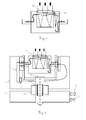
- Fig. 1 shows a rotor 1, on which a rotary body 2 is rotatably mounted about a horizontal axis on the pivot bearings 3.
- a first rotary drive not shown here, the rotor 1 is movable about a vertical axis, wherein the rotational position can be determined by a first protractor.
- a second rotary drive 26 the rotary body 2 is rotated. The rotational position of the rotating body 2 is detected by a second protractor 4.
- An evaluation electronics 5 in the rotor 1 is with a laser source 6 (laser) and a laser light detector 7 (APD) of the distance measuring device connected.
- laser laser source 6
- APD laser light detector
- the laser light originating from the laser source 6 is guided in the rotor 1 through an optical waveguide 8 from the laser source 6 to an optical link 9 between the rotor 1 and the rotary body 2.
- a multimode fiber of, for example, 50 ⁇ m core diameter and a numerical aperture of, for example, 0.12 is recommended.
- the optical link 9 comprises two fiber ferrules 10 (fiber connectors) and an air gap of a few micrometers, wherein the one ferrule is fixedly mounted in the rotary body 2 and rotates and the other is supported in the rotor 1 directly in the axis of rotation.
- the optical link 9 also comprises a lens 11 for optimal transmission of the laser light.
- a light guide 8 guides the transmitted light to an exit point 16 from which it exits the rotary body 2 via two first mirrors 12 and one central lens 13.
- the two first mirrors 12 are arranged in the rotary body 2 at a passage boundary 33.
- the transmission light is conducted between the two first mirrors 12 from a lateral area to the central lens 13.
- the laser light scattered back from the object area passes through a ring lens 14 and two second mirrors 15 to an entry point 17 of a light guide 8.
- the received light arrives at the detector 7 via an optical link 9 and the adjoining light guide 8.
- the evaluation electronics determines signals from the signals Laser source 6 and the detector 7 distance values, which are assigned to the corresponding Drehauscardi the second protractor 4.
- the orientation of the rotor 1 relative to a stator is detected by a first protractor, not shown. Each detected distance value may be associated with a spatial orientation determined by two alignment values.
- the transmission optics with a focal length of 50 mm requires an exit pupil of 12 mm diameter.
- the optics can be a multiple lens or consist of an (aspheric) Einzellinse.
- the receiving optics are designed with a focal length of 80 mm and a diameter of 30 mm significantly larger and receives the transmission optics in the central area.
- a through-bore of the receiving lens with the transmitting optics is suitable as a slot, or a complex glass press with two different focal lengths, or the combination of the receiving optics with a diffractive element in the central region, to achieve a higher refractive power.
- Fig. 3 Also feasible is a design of the optics as shown in Fig. 3, in which the same front lens 13a is used for receiving and transmitting optics, in conjunction with another lens element 13b in the transmission channel, resulting in the desired shortened focal length.
- the received light is imaged via a folded beam path, consisting of two second mirrors 15, onto a light guide 8 with a core diameter of 200 ⁇ m.
- the second mirrors 15 may also be curved to further reduce the size of the structure.
- the received light is conducted via an optical link 9, which is designed similarly to the transmission channel, in the rotor 1 to a detector 7. All electronic components can thus be kept outside the rotary body 2.
- the transmitting and receiving optics always remain aligned with each other in contrast to previous embodiments in which the mirror is permanently moved relative to the rest of the optics, which leads to constantly changing imaging situations and is relatively easy to adjust or error prone.
- Fig. 2 shows a laser source 6 in the form of a diode broad-band emitter 18 with dimensions of 60 ⁇ m wide (slow axis) and 2 ⁇ m narrow (fast axis).
- the laser light of this emitter is coupled with a micro-optics in the rotationally symmetrical light guide 8 with a diameter of 50 microns.
- the micro-optics of Embodiment comprises a cylindrical lens 19 and a spherical lens 20, wherein the line focus of the emitter 18 is converted to an approximately square focus.
- A. of the arrow Beam shaping of wide area laser diode: principles and benefits", Proc. SPIE Vol. 4648 Test and Measurement Applications of Optoelectronic Devices , Segmenting beamforming optics are known. These new optics can stack a line focus in sections to a square focus.
- a laser scanner thus comprises the stator 21, the rotor 1 rotatably mounted on the stator 21 about a first rotation axis, the rotary body 2 rotatably mounted on the rotor 1 about a second rotation axis, the evaluation electronics 5, the laser source 6 and the laser light detector 7
- the passage of transmitted light and received light, the rotary body 2 comprises a parallel to the second axis of rotation füreriesberandung 33rd
- a desired scanning movement is effected by a corresponding control of the first rotary drive 25 and the second rotary drive 26.
- the spatial orientation of the rotary body 2 is detected by the two protractors 4.
- the detector 7 is arranged directly at the optical link 9. This makes it possible to dispense with a light guide for the transmission of the received light from the optical link 9 to the detector.
- the rear second mirror 15 of the receiving optics is partially transparent. Behind this partially transmissive second mirror 15, a deflection mirror 27 and a compact CCD camera 28 can be installed in the rotary body 2.
- the camera 28 allows a visual inspection of the receiving channel.
- a rotary feedthrough 29 is used for the camera 28.
- the power supply of the camera 28 can also be done optically by light in the fiber zw.
- Laseretti 6 and the link 9 via a chromatic beam splitter light of a different wavelength from a separate source (100 mW) is coupled and in the turret over a same beam splitter again decoupled and directed to a photovoltaic component or solar cell, which takes over the necessary supply to the camera.
- the data transmission can optically via a modulated signal again via a beam splitter via output fiber.
- Corresponding low-current components are known and available, for example, from mobile radio technology.
- the texture of the object to be scanned can be detected.
- a simple spectral sensor can also be used. Set the entire scene to be scanned in advance can be detected quickly, as well as in the rotor (1) laterally adjacent to the rotor body (2) arranged camera with a corresponding zoom optics can be realized.
- a reference unit 30 similar to the embodiment in DE 102 16 405 be grown to allow a complete calibration of the distance measuring device.
- the reference unit 30 consists in the simplest case of a target in the known distance to obtain a distance standard during rotation of the measuring head.
- the reflectivity of the target may vary to allow dynamic distance calibration.
- the solid-state laser 31 is, for example, a ⁇ -chip laser (Nd: YAG) Q-switched with a saturable absorber (Cr 4+ : YAG). Because of the high peak power in the kW range, a fiber transmission due to the damage threshold is critical.
- the pump light from the pump laser 6 (808 nm) can be guided via the optical link 9 into the rotary body 2 and there excite the solid-state laser 31.
- the exiting laser light does not have to be guided through a lens but can emerge from the rotary body 2 through an exit hole 32.
- any other beam path for example with transmit beam path and receive beam path can be provided laterally side by side instead of the described folded beam path.
Landscapes
- Engineering & Computer Science (AREA)
- Physics & Mathematics (AREA)
- Computer Networks & Wireless Communication (AREA)
- General Physics & Mathematics (AREA)
- Radar, Positioning & Navigation (AREA)
- Remote Sensing (AREA)
- Electromagnetism (AREA)
- Optical Radar Systems And Details Thereof (AREA)
- Length Measuring Devices By Optical Means (AREA)
- Optical Communication System (AREA)
- Optical Couplings Of Light Guides (AREA)
Priority Applications (9)
| Application Number | Priority Date | Filing Date | Title |
|---|---|---|---|
| EP06119147A EP1890168A1 (fr) | 2006-08-18 | 2006-08-18 | Scanner à laser |
| CA2659721A CA2659721C (fr) | 2006-08-18 | 2007-08-16 | Lecteur laser |
| US12/377,278 US7933055B2 (en) | 2006-08-18 | 2007-08-16 | Laser scanner |
| EP07801703A EP2052278B1 (fr) | 2006-08-18 | 2007-08-16 | Scanner a laser |
| AU2007286404A AU2007286404B2 (en) | 2006-08-18 | 2007-08-16 | Laser scanner |
| CN2007800307944A CN101506684B (zh) | 2006-08-18 | 2007-08-16 | 激光扫描器 |
| JP2009524128A JP5135343B2 (ja) | 2006-08-18 | 2007-08-16 | レーザースキャナ |
| AT07801703T ATE528665T1 (de) | 2006-08-18 | 2007-08-16 | Laserscanner |
| PCT/EP2007/007249 WO2008019856A1 (fr) | 2006-08-18 | 2007-08-16 | Lecteur laser |
Applications Claiming Priority (1)
| Application Number | Priority Date | Filing Date | Title |
|---|---|---|---|
| EP06119147A EP1890168A1 (fr) | 2006-08-18 | 2006-08-18 | Scanner à laser |
Publications (1)
| Publication Number | Publication Date |
|---|---|
| EP1890168A1 true EP1890168A1 (fr) | 2008-02-20 |
Family
ID=37685303
Family Applications (2)
| Application Number | Title | Priority Date | Filing Date |
|---|---|---|---|
| EP06119147A Withdrawn EP1890168A1 (fr) | 2006-08-18 | 2006-08-18 | Scanner à laser |
| EP07801703A Active EP2052278B1 (fr) | 2006-08-18 | 2007-08-16 | Scanner a laser |
Family Applications After (1)
| Application Number | Title | Priority Date | Filing Date |
|---|---|---|---|
| EP07801703A Active EP2052278B1 (fr) | 2006-08-18 | 2007-08-16 | Scanner a laser |
Country Status (8)
| Country | Link |
|---|---|
| US (1) | US7933055B2 (fr) |
| EP (2) | EP1890168A1 (fr) |
| JP (1) | JP5135343B2 (fr) |
| CN (1) | CN101506684B (fr) |
| AT (1) | ATE528665T1 (fr) |
| AU (1) | AU2007286404B2 (fr) |
| CA (1) | CA2659721C (fr) |
| WO (1) | WO2008019856A1 (fr) |
Cited By (11)
| Publication number | Priority date | Publication date | Assignee | Title |
|---|---|---|---|---|
| CN101614539B (zh) * | 2008-06-27 | 2011-05-04 | 北京航天计量测试技术研究所 | 分离式方位角垂直传递装置 |
| EP2759845A1 (fr) * | 2013-01-28 | 2014-07-30 | Sick Ag | Capteur optoélectronique |
| EP2833161A1 (fr) * | 2013-07-31 | 2015-02-04 | Valeo Schalter und Sensoren GmbH | Dispositif de mesure optoélectronique pour un véhicule automobile et capteur à balayage associé |
| EP2827173A3 (fr) * | 2013-07-18 | 2015-05-20 | Sick Ag | Capteur optoélectronique et procédé destiné à la détection d'objets |
| EP2645125B1 (fr) * | 2012-03-27 | 2017-05-10 | Sick AG | Laser scanner et procédé destiné à la détection d'objets dans une zone de surveillance |
| WO2019020532A1 (fr) * | 2017-07-27 | 2019-01-31 | Robert Bosch Gmbh | Dispositif lidar et procédé doté d'un dispositif de déviation amélioré |
| WO2019211135A1 (fr) * | 2018-05-03 | 2019-11-07 | Robert Bosch Gmbh | Assemblage pour un capteur lidar, capteur lidar et moyen de transport |
| EP3579174A1 (fr) | 2018-06-08 | 2019-12-11 | Hexagon Technology Center GmbH | Véhicules mobiles dans la fabrication |
| EP3623843A1 (fr) | 2018-09-11 | 2020-03-18 | Leica Geosystems AG | Appareil de mesure de distance laser portatif |
| EP4063897A1 (fr) | 2021-03-25 | 2022-09-28 | Hexagon Geosystems Services AG | Procédé mis en uvre par ordinateur pour identifier les candidats d'aéronefs transparents et /ou en miroir et uav utilisant ce procédé |
| EP4266110A4 (fr) * | 2020-12-16 | 2024-06-26 | Sony Group Corporation | Module optique et dispositif de télémétrie |
Families Citing this family (62)
| Publication number | Priority date | Publication date | Assignee | Title |
|---|---|---|---|---|
| DE102006031580A1 (de) | 2006-07-03 | 2008-01-17 | Faro Technologies, Inc., Lake Mary | Verfahren und Vorrichtung zum dreidimensionalen Erfassen eines Raumbereichs |
| EP2100454B1 (fr) | 2006-11-20 | 2019-10-30 | Axis AB | Systèmes de réseau de caméras sans fil |
| EP2238758A4 (fr) | 2008-01-24 | 2013-12-18 | Micropower Technologies Inc | Systèmes de distribution de vidéo utilisant des caméras sans fil |
| JP5250286B2 (ja) * | 2008-03-27 | 2013-07-31 | 株式会社ミツトヨ | 追尾式レーザ干渉計 |
| DE102009010465B3 (de) | 2009-02-13 | 2010-05-27 | Faro Technologies, Inc., Lake Mary | Laserscanner |
| DE102009015920B4 (de) | 2009-03-25 | 2014-11-20 | Faro Technologies, Inc. | Vorrichtung zum optischen Abtasten und Vermessen einer Umgebung |
| US9551575B2 (en) | 2009-03-25 | 2017-01-24 | Faro Technologies, Inc. | Laser scanner having a multi-color light source and real-time color receiver |
| DE102009035337A1 (de) | 2009-07-22 | 2011-01-27 | Faro Technologies, Inc., Lake Mary | Verfahren zum optischen Abtasten und Vermessen eines Objekts |
| US9210288B2 (en) | 2009-11-20 | 2015-12-08 | Faro Technologies, Inc. | Three-dimensional scanner with dichroic beam splitters to capture a variety of signals |
| US9113023B2 (en) | 2009-11-20 | 2015-08-18 | Faro Technologies, Inc. | Three-dimensional scanner with spectroscopic energy detector |
| DE102009055989B4 (de) | 2009-11-20 | 2017-02-16 | Faro Technologies, Inc. | Vorrichtung zum optischen Abtasten und Vermessen einer Umgebung |
| US9529083B2 (en) | 2009-11-20 | 2016-12-27 | Faro Technologies, Inc. | Three-dimensional scanner with enhanced spectroscopic energy detector |
| DE102009055988B3 (de) | 2009-11-20 | 2011-03-17 | Faro Technologies, Inc., Lake Mary | Vorrichtung zum optischen Abtasten und Vermessen einer Umgebung |
| DE102009057101A1 (de) | 2009-11-20 | 2011-05-26 | Faro Technologies, Inc., Lake Mary | Vorrichtung zum optischen Abtasten und Vermessen einer Umgebung |
| US9879976B2 (en) | 2010-01-20 | 2018-01-30 | Faro Technologies, Inc. | Articulated arm coordinate measurement machine that uses a 2D camera to determine 3D coordinates of smoothly continuous edge features |
| US9607239B2 (en) | 2010-01-20 | 2017-03-28 | Faro Technologies, Inc. | Articulated arm coordinate measurement machine having a 2D camera and method of obtaining 3D representations |
| US9163922B2 (en) | 2010-01-20 | 2015-10-20 | Faro Technologies, Inc. | Coordinate measurement machine with distance meter and camera to determine dimensions within camera images |
| DE112011100292B4 (de) | 2010-01-20 | 2016-11-24 | Faro Technologies Inc. | Anzeige für ein Koordinatenmessgerät |
| US9628775B2 (en) | 2010-01-20 | 2017-04-18 | Faro Technologies, Inc. | Articulated arm coordinate measurement machine having a 2D camera and method of obtaining 3D representations |
| DE102010020925B4 (de) * | 2010-05-10 | 2014-02-27 | Faro Technologies, Inc. | Verfahren zum optischen Abtasten und Vermessen einer Umgebung |
| DE102010032723B3 (de) | 2010-07-26 | 2011-11-24 | Faro Technologies, Inc. | Vorrichtung zum optischen Abtasten und Vermessen einer Umgebung |
| DE102010032726B3 (de) | 2010-07-26 | 2011-11-24 | Faro Technologies, Inc. | Vorrichtung zum optischen Abtasten und Vermessen einer Umgebung |
| DE102010032725B4 (de) | 2010-07-26 | 2012-04-26 | Faro Technologies, Inc. | Vorrichtung zum optischen Abtasten und Vermessen einer Umgebung |
| DE102010033561B3 (de) | 2010-07-29 | 2011-12-15 | Faro Technologies, Inc. | Vorrichtung zum optischen Abtasten und Vermessen einer Umgebung |
| JP2013545976A (ja) * | 2010-10-25 | 2013-12-26 | 株式会社ニコン | 装置、光学アセンブリ、物体を検査又は測定する方法、及び構造体を製造する方法 |
| US9168654B2 (en) | 2010-11-16 | 2015-10-27 | Faro Technologies, Inc. | Coordinate measuring machines with dual layer arm |
| JP5701686B2 (ja) * | 2011-05-26 | 2015-04-15 | 株式会社レクザム | レーザ変位計 |
| US9594156B2 (en) | 2011-07-26 | 2017-03-14 | Hexagon Technology Center Gmbh | Laser scanner having means for capturing a spatial direction to the point on a surface |
| EP2607843A1 (fr) * | 2011-12-20 | 2013-06-26 | Leica Geosystems AG | Appareil de mesure de coordonnées basé sur laser et doté d'un dispositif de palier fixe-libre |
| DE102012100609A1 (de) | 2012-01-25 | 2013-07-25 | Faro Technologies, Inc. | Vorrichtung zum optischen Abtasten und Vermessen einer Umgebung |
| US8997362B2 (en) | 2012-07-17 | 2015-04-07 | Faro Technologies, Inc. | Portable articulated arm coordinate measuring machine with optical communications bus |
| DE102012107544B3 (de) | 2012-08-17 | 2013-05-23 | Faro Technologies, Inc. | Vorrichtung zum optischen Abtasten und Vermessen einer Umgebung |
| DE102012109481A1 (de) | 2012-10-05 | 2014-04-10 | Faro Technologies, Inc. | Vorrichtung zum optischen Abtasten und Vermessen einer Umgebung |
| US9513107B2 (en) | 2012-10-05 | 2016-12-06 | Faro Technologies, Inc. | Registration calculation between three-dimensional (3D) scans based on two-dimensional (2D) scan data from a 3D scanner |
| US10067231B2 (en) | 2012-10-05 | 2018-09-04 | Faro Technologies, Inc. | Registration calculation of three-dimensional scanner data performed between scans based on measurements by two-dimensional scanner |
| EP2860492B1 (fr) * | 2013-10-09 | 2018-02-28 | Hexagon Technology Center GmbH | Appareil de mesure pour le balayage optique d'un environnement |
| KR101517971B1 (ko) * | 2013-12-05 | 2015-05-06 | (주)이오시스템 | 반사경 회전체를 구비한 지상용 3차원 레이저 스캐너 |
| CN104061900A (zh) * | 2014-06-27 | 2014-09-24 | 广州市科创电脑技术开发有限公司 | 智能旋转式测绘系统及方法 |
| US9632166B2 (en) | 2015-09-17 | 2017-04-25 | Raytheon Company | Optical waveguide coude path for gimbaled systems having an optical coupling element |
| JP2017106833A (ja) * | 2015-12-10 | 2017-06-15 | 船井電機株式会社 | 測定装置 |
| DE102015122844A1 (de) | 2015-12-27 | 2017-06-29 | Faro Technologies, Inc. | 3D-Messvorrichtung mit Batteriepack |
| DE102015226773A1 (de) * | 2015-12-29 | 2017-06-29 | Robert Bosch Gmbh | Scaneinrichtung |
| CN105785384A (zh) * | 2016-05-19 | 2016-07-20 | 上海思岚科技有限公司 | 一种激光扫描测距装置 |
| DE102016119155A1 (de) * | 2016-09-15 | 2018-03-15 | Zoller + Fröhlich GmbH | Laserscanner |
| US10359507B2 (en) * | 2016-12-30 | 2019-07-23 | Panosense Inc. | Lidar sensor assembly calibration based on reference surface |
| KR102353513B1 (ko) * | 2017-03-16 | 2022-01-20 | 주식회사 히타치엘지 데이터 스토리지 코리아 | 회전 거리 측정 장치 |
| DE102017205504A1 (de) | 2017-03-31 | 2018-10-04 | Robert Bosch Gmbh | Optisches Scansystem |
| DE202017105001U1 (de) * | 2017-08-21 | 2017-09-14 | Jenoptik Advanced Systems Gmbh | LIDAR-Scanner mit MEMS-Spiegel und wenigstens zwei Scanwinkelbereichen |
| CN108803006B (zh) * | 2017-09-18 | 2021-01-05 | 成都理想境界科技有限公司 | 光纤扫描成像系统、设备及其畸变检测与矫正系统 |
| US11340336B2 (en) | 2017-12-07 | 2022-05-24 | Ouster, Inc. | Rotating light ranging system with optical communication uplink and downlink channels |
| US10707195B2 (en) | 2018-10-09 | 2020-07-07 | Waymo Llc | Multichannel monostatic rangefinder |
| CN109581394A (zh) * | 2018-12-12 | 2019-04-05 | 广州维思车用部件有限公司 | 激光雷达及激光雷达的测量方法 |
| DE102018222416B4 (de) * | 2018-12-20 | 2023-01-26 | Robert Bosch Gmbh | Baugruppe für einen LiDAR-Sensor und LiDAR-Sensor |
| CN109814109B (zh) * | 2019-01-07 | 2020-12-08 | Oppo广东移动通信有限公司 | 电子设备及电子设备控制方法 |
| CN110109136A (zh) * | 2019-06-12 | 2019-08-09 | 卡门哈斯激光科技(苏州)有限公司 | 一种紧凑激光雷达测距光学系统 |
| DE102019214189A1 (de) * | 2019-09-18 | 2021-03-18 | Robert Bosch Gmbh | Senderoptik für ein Lichterfassungssystem, Lichterfassungssystem und Arbeitsvorrichtung |
| EP4043913A4 (fr) * | 2019-10-10 | 2022-11-09 | Suteng Innovation Technology Co., Ltd | Appareil de transmission de données, lidar, et dispositif intelligent |
| EP4071504B1 (fr) | 2021-04-09 | 2023-03-22 | Sick Ag | Capteur optoélectronique et procédé de détection d'objets |
| CN115685218A (zh) * | 2021-07-21 | 2023-02-03 | 广东博智林机器人有限公司 | 激光探测装置 |
| US20230184939A1 (en) * | 2021-12-14 | 2023-06-15 | Apple Inc. | Proximity sensor utilizing optical fibers |
| CN118603882B (zh) * | 2024-08-05 | 2025-01-03 | 小鳄生物技术(苏州)有限公司 | 多通道光学检测装置 |
| DE102024130180A1 (de) * | 2024-10-17 | 2026-04-23 | Pepperl+Fuchs Se | Optischer scanner |
Citations (9)
| Publication number | Priority date | Publication date | Assignee | Title |
|---|---|---|---|---|
| EP0035054A1 (fr) * | 1980-02-28 | 1981-09-09 | AEG - TELEFUNKEN Nachrichtentechnik GmbH | Joint rotatif pour guide d'ondes optiques |
| GB2163617A (en) * | 1982-12-28 | 1986-02-26 | Thomson Csf | Optical coupling device with rotating joint |
| WO1993001465A1 (fr) * | 1991-07-02 | 1993-01-21 | Ltv Missiles And Electronics Group | Systeme optique pour appareil de guidage par laser |
| DE29518708U1 (de) * | 1995-11-25 | 1996-01-18 | Carl Zeiss Jena Gmbh, 07745 Jena | Geodätische Laserstation |
| EP1241486A2 (fr) * | 2001-03-12 | 2002-09-18 | BODENSEEWERK GERÄTETECHNIK GmbH | Dispositif d'alignement d'un rayon laser à une cible |
| DE10304188A1 (de) * | 2003-01-29 | 2004-08-19 | Iqsun Gmbh | 3D-Scanner |
| WO2004109323A2 (fr) * | 2003-06-04 | 2004-12-16 | Elop Electro-Optical Industries Ltd. | Systeme de brouillage faisant appel a un laser a fibres |
| EP1562055A2 (fr) * | 2004-02-04 | 2005-08-10 | Nidec Corporation | Télémètre optique à balayage |
| US20050279914A1 (en) * | 2004-03-16 | 2005-12-22 | Jerry Dimsdale | Contact-free slip ring for survey instrumentation |
Family Cites Families (4)
| Publication number | Priority date | Publication date | Assignee | Title |
|---|---|---|---|---|
| US5039193A (en) * | 1990-04-03 | 1991-08-13 | Focal Technologies Incorporated | Fibre optic single mode rotary joint |
| US5157745A (en) * | 1991-09-16 | 1992-10-20 | The United States Of America As Represented By The Secretary Of The Navy | Multi-channel fiber optic rotary joint for single-mode fiber |
| JP4828694B2 (ja) * | 2000-12-26 | 2011-11-30 | 株式会社トプコン | 測定装置 |
| EP1503175A1 (fr) * | 2003-07-28 | 2005-02-02 | Leica Geosystems AG | Dispositif et procédé de calibrage de l'alignement d'un dispositif à tester |
-
2006
- 2006-08-18 EP EP06119147A patent/EP1890168A1/fr not_active Withdrawn
-
2007
- 2007-08-16 WO PCT/EP2007/007249 patent/WO2008019856A1/fr not_active Ceased
- 2007-08-16 JP JP2009524128A patent/JP5135343B2/ja not_active Expired - Fee Related
- 2007-08-16 CA CA2659721A patent/CA2659721C/fr not_active Expired - Fee Related
- 2007-08-16 US US12/377,278 patent/US7933055B2/en active Active
- 2007-08-16 AU AU2007286404A patent/AU2007286404B2/en not_active Ceased
- 2007-08-16 EP EP07801703A patent/EP2052278B1/fr active Active
- 2007-08-16 CN CN2007800307944A patent/CN101506684B/zh active Active
- 2007-08-16 AT AT07801703T patent/ATE528665T1/de active
Patent Citations (9)
| Publication number | Priority date | Publication date | Assignee | Title |
|---|---|---|---|---|
| EP0035054A1 (fr) * | 1980-02-28 | 1981-09-09 | AEG - TELEFUNKEN Nachrichtentechnik GmbH | Joint rotatif pour guide d'ondes optiques |
| GB2163617A (en) * | 1982-12-28 | 1986-02-26 | Thomson Csf | Optical coupling device with rotating joint |
| WO1993001465A1 (fr) * | 1991-07-02 | 1993-01-21 | Ltv Missiles And Electronics Group | Systeme optique pour appareil de guidage par laser |
| DE29518708U1 (de) * | 1995-11-25 | 1996-01-18 | Carl Zeiss Jena Gmbh, 07745 Jena | Geodätische Laserstation |
| EP1241486A2 (fr) * | 2001-03-12 | 2002-09-18 | BODENSEEWERK GERÄTETECHNIK GmbH | Dispositif d'alignement d'un rayon laser à une cible |
| DE10304188A1 (de) * | 2003-01-29 | 2004-08-19 | Iqsun Gmbh | 3D-Scanner |
| WO2004109323A2 (fr) * | 2003-06-04 | 2004-12-16 | Elop Electro-Optical Industries Ltd. | Systeme de brouillage faisant appel a un laser a fibres |
| EP1562055A2 (fr) * | 2004-02-04 | 2005-08-10 | Nidec Corporation | Télémètre optique à balayage |
| US20050279914A1 (en) * | 2004-03-16 | 2005-12-22 | Jerry Dimsdale | Contact-free slip ring for survey instrumentation |
Non-Patent Citations (1)
| Title |
|---|
| VON PFEIL A ET AL: "Beam shaping of broad-area diode lasers: principles and benefits", PROCEEDINGS OF THE SPIE - THE INTERNATIONAL SOCIETY FOR OPTICAL ENGINEERING SPIE-INT. SOC. OPT. ENG USA, vol. 4648, 2002, pages 82 - 90, XP002419031, ISSN: 0277-786X * |
Cited By (15)
| Publication number | Priority date | Publication date | Assignee | Title |
|---|---|---|---|---|
| CN101614539B (zh) * | 2008-06-27 | 2011-05-04 | 北京航天计量测试技术研究所 | 分离式方位角垂直传递装置 |
| EP2645125B1 (fr) * | 2012-03-27 | 2017-05-10 | Sick AG | Laser scanner et procédé destiné à la détection d'objets dans une zone de surveillance |
| EP2759845A1 (fr) * | 2013-01-28 | 2014-07-30 | Sick Ag | Capteur optoélectronique |
| EP2827173A3 (fr) * | 2013-07-18 | 2015-05-20 | Sick Ag | Capteur optoélectronique et procédé destiné à la détection d'objets |
| EP2833161A1 (fr) * | 2013-07-31 | 2015-02-04 | Valeo Schalter und Sensoren GmbH | Dispositif de mesure optoélectronique pour un véhicule automobile et capteur à balayage associé |
| WO2019020532A1 (fr) * | 2017-07-27 | 2019-01-31 | Robert Bosch Gmbh | Dispositif lidar et procédé doté d'un dispositif de déviation amélioré |
| WO2019211135A1 (fr) * | 2018-05-03 | 2019-11-07 | Robert Bosch Gmbh | Assemblage pour un capteur lidar, capteur lidar et moyen de transport |
| EP3579174A1 (fr) | 2018-06-08 | 2019-12-11 | Hexagon Technology Center GmbH | Véhicules mobiles dans la fabrication |
| WO2019234249A1 (fr) | 2018-06-08 | 2019-12-12 | Hexagon Technology Center Gmbh | Véhicules mobiles dans la fabrication |
| US11282013B2 (en) | 2018-06-08 | 2022-03-22 | Hexagon Technology Center Gmbh | Mobile vehicles in manufacturing |
| EP3623843A1 (fr) | 2018-09-11 | 2020-03-18 | Leica Geosystems AG | Appareil de mesure de distance laser portatif |
| US11789126B2 (en) | 2018-09-11 | 2023-10-17 | Leica Geosystems Ag | Handheld laser distance meter |
| EP4266110A4 (fr) * | 2020-12-16 | 2024-06-26 | Sony Group Corporation | Module optique et dispositif de télémétrie |
| EP4063897A1 (fr) | 2021-03-25 | 2022-09-28 | Hexagon Geosystems Services AG | Procédé mis en uvre par ordinateur pour identifier les candidats d'aéronefs transparents et /ou en miroir et uav utilisant ce procédé |
| US12379504B2 (en) | 2021-03-25 | 2025-08-05 | Hexagon Geosystems Services Ag | Computer implemented method for identifying transparent and/or mirroring plane candidates and UAV using the same |
Also Published As
| Publication number | Publication date |
|---|---|
| AU2007286404B2 (en) | 2010-08-26 |
| CA2659721A1 (fr) | 2008-02-21 |
| JP2010501069A (ja) | 2010-01-14 |
| EP2052278A1 (fr) | 2009-04-29 |
| US7933055B2 (en) | 2011-04-26 |
| CA2659721C (fr) | 2015-04-21 |
| US20100208318A1 (en) | 2010-08-19 |
| WO2008019856A1 (fr) | 2008-02-21 |
| CN101506684B (zh) | 2012-05-30 |
| EP2052278B1 (fr) | 2011-10-12 |
| ATE528665T1 (de) | 2011-10-15 |
| CN101506684A (zh) | 2009-08-12 |
| AU2007286404A1 (en) | 2008-02-21 |
| JP5135343B2 (ja) | 2013-02-06 |
Similar Documents
| Publication | Publication Date | Title |
|---|---|---|
| EP2052278B1 (fr) | Scanner a laser | |
| EP3673290B1 (fr) | Dispositif d'émission pour un scanner lidar présentant un miroir de balayage recouvert par un élément de recouvrement | |
| EP2378309B1 (fr) | Capteur optoélectronique et procédé de production d'informations sur des objets dans une zone de surveillance | |
| EP1971821B1 (fr) | Appareil de mesure de coordonnees | |
| DE2834821C2 (de) | Einrichtung zum Überprüfen der Betriebseigenschaften von Laser-Entfernungsmeßgeräten | |
| EP2827173B1 (fr) | Capteur optoélectronique et procédé destiné à la détection d'objets | |
| EP3474033A1 (fr) | Module d'émission et de réception pour un capteur optoélectronique et procédé de détection d'objets | |
| DE102017213465B4 (de) | Lichtleiter-basiertes LiDAR-System | |
| EP3432023B1 (fr) | Procédé de fabrication d'un capteur optoélectronique | |
| DE10051302C5 (de) | Laserentfernungsmessgerät für den Nah- und Fernbereich mit speziellem Empfänger | |
| EP3605139A1 (fr) | Capteur optoélectronique et procédé de détection d'un objet | |
| EP2645125A1 (fr) | Capteur optoélectronique et procédé destiné à la détection d'objets dans une zone de surveillance | |
| EP4071504B1 (fr) | Capteur optoélectronique et procédé de détection d'objets | |
| WO2011023484A1 (fr) | Dispositif de mesure optique de distance, et procédé de réglage d'un tel dispositif | |
| EP1695109B1 (fr) | Dispositif pour mesurer la distance a des objets proches et eloignes | |
| EP3502617B1 (fr) | Dispositif de mesure à homogénéisation du faisceau de mesure | |
| EP2375266B1 (fr) | Capteur optoélectronique et procédé de sécurisation | |
| DE10330647A1 (de) | Vorrichtung zur Übertragung optischer Signale zwischen einem rotierenden und einem stationären Teil einer Maschine | |
| DE102007030880A1 (de) | Vorrichtung zur Erfassung einer Objektszene | |
| WO2006005285A1 (fr) | Dispositif d'exploration pour la mesure des contours d'un objet | |
| DE202013103233U1 (de) | Optoelektronischer Sensor zur Erfassung von Objekten | |
| EP1743139B1 (fr) | Appareil d'acquisition de cible | |
| DE102017215671A1 (de) | Scansystem und Sende- und Empfangsvorrichtung für ein Scansystem | |
| DE102017012251A1 (de) | Sende-Empfangsmodul für einen optoelektronischen Sensor und Verfahren zur Erfassung von Objekten | |
| DE19904461C2 (de) | Anordnung zur berührungslosen Übertragung von Daten |
Legal Events
| Date | Code | Title | Description |
|---|---|---|---|
| PUAI | Public reference made under article 153(3) epc to a published international application that has entered the european phase |
Free format text: ORIGINAL CODE: 0009012 |
|
| AK | Designated contracting states |
Kind code of ref document: A1 Designated state(s): AT BE BG CH CY CZ DE DK EE ES FI FR GB GR HU IE IS IT LI LT LU LV MC NL PL PT RO SE SI SK TR |
|
| AX | Request for extension of the european patent |
Extension state: AL BA HR MK YU |
|
| AKX | Designation fees paid | ||
| REG | Reference to a national code |
Ref country code: DE Ref legal event code: 8566 |
|
| STAA | Information on the status of an ep patent application or granted ep patent |
Free format text: STATUS: THE APPLICATION IS DEEMED TO BE WITHDRAWN |
|
| 18D | Application deemed to be withdrawn |
Effective date: 20080821 |