EP1890263A2 - Procédé pour l'affinement du modèle d'ADN avec estimation de pose pour la représentation vidéo d'une scène tridimensionnelle - Google Patents
Procédé pour l'affinement du modèle d'ADN avec estimation de pose pour la représentation vidéo d'une scène tridimensionnelle Download PDFInfo
- Publication number
- EP1890263A2 EP1890263A2 EP07075960A EP07075960A EP1890263A2 EP 1890263 A2 EP1890263 A2 EP 1890263A2 EP 07075960 A EP07075960 A EP 07075960A EP 07075960 A EP07075960 A EP 07075960A EP 1890263 A2 EP1890263 A2 EP 1890263A2
- Authority
- EP
- European Patent Office
- Prior art keywords
- model
- scene
- image
- images
- pose
- Prior art date
- Legal status (The legal status is an assumption and is not a legal conclusion. Google has not performed a legal analysis and makes no representation as to the accuracy of the status listed.)
- Withdrawn
Links
Images




Classifications
-
- G—PHYSICS
- G06—COMPUTING OR CALCULATING; COUNTING
- G06T—IMAGE DATA PROCESSING OR GENERATION, IN GENERAL
- G06T17/00—Three-dimensional [3D] modelling for computer graphics
- G06T17/10—Constructive solid geometry [CSG] using solid primitives, e.g. cylinders, cubes
-
- G—PHYSICS
- G06—COMPUTING OR CALCULATING; COUNTING
- G06T—IMAGE DATA PROCESSING OR GENERATION, IN GENERAL
- G06T7/00—Image analysis
- G06T7/80—Analysis of captured images to determine intrinsic or extrinsic camera parameters, i.e. camera calibration
-
- G—PHYSICS
- G06—COMPUTING OR CALCULATING; COUNTING
- G06V—IMAGE OR VIDEO RECOGNITION OR UNDERSTANDING
- G06V10/00—Arrangements for image or video recognition or understanding
- G06V10/10—Image acquisition
- G06V10/12—Details of acquisition arrangements; Constructional details thereof
- G06V10/14—Optical characteristics of the device performing the acquisition or on the illumination arrangements
- G06V10/147—Details of sensors, e.g. sensor lenses
Definitions
- the present invention is directed toward the domain of image processing, in particular toward the creation and manipulation of three dimensional scene models and virtual images of the scene seen from arbitrary viewpoints.
- That constraint must come from physical measurements like GPS, or surveyed landmarks, or from a prior scene model with shape and/or texture information.
- the problem of loss of metric accuracy is particularly acute for analysis and control of a remote scene in which use of such constraint indicia is not practical, for example to control a remote vehicle on Mars or underground.
- the present invention is embodied in a method of accurately estimating a pose of a camera within a scene using a three dimensional model of the scene.
- the exemplary method begins by generating an initial estimate of the camera pose. Next, a set of relevant features of the three-dimensional model based on the estimate of the pose is selected. A virtual projection of this set of relevant features as seen from the estimated pose is then created. The virtual projection of the set of relevant features is matched to features of the received image and matching errors between the features of the image and the features of the projection are measured. The estimate of the pose is then updated to reduce the matching errors.
- a second embodiment of the present invention is method of refining a three dimensional model of a scene using an image of the scene taken by a camera, which may have an unknown pose. First the image is compared to the three dimensional model of the scene to generate an estimate of the camera pose. The three dimensional model of the scene is then updated based on data from the image and the estimated pose.
- Another embodiment of the present invention is a method of accurately estimating a position of remote vehicle using a three dimensional model and an image from a camera having a known orientation relative to the remote vehicle.
- the image is compared to the three dimensional model of the scene to generate an initial estimate of the pose.
- a set of relevant features of the three dimensional model are selected and matched to features of the image. Matching errors are then measured and used to update the estimate of the pose.
- the position of the remote vehicle is determined using the estimated pose and the orientation of the camera.
- the three dimensional model may then be updated based on data from the image and the estimate of the pose.
- Yet another embodiment of the present invention is a method of refining a three dimensional model of a scene containing an object using a plurality of images of the scene.
- a first image and a second image are compared to the three dimensional model of the scene to generate first and second pose estimates.
- the first image and the second image are compared to one another to generate relative pose constraints.
- the first pose and the second pose are updated based on these relative pose constraints.
- Two sets of relevant features of the three-dimensional model corresponding to the first pose and the second pose are selected. These sets of relevant features are then matched to features in the first and second images, and two sets of matching errors are measured.
- the position estimate of the object within the three-dimensional model is then updated to reduce the two sets of matching errors.
- the present invention is also embodied in a method of creating a textured three-dimensional model of a scene using a plurality of images of the scene.
- First a polyhedral model the scene including a plurality of polygonal surfaces is created. Each polygonal surface in the polyhedral model is larger than a predetermined size.
- One polygonal surface is then separated into a plurality of portions. For a selected portion, a subset of images containing that portion of the polygonal surface is identified. The corresponding section of the selected image is then projected onto the selected portion of the polygonal surface in the textured three-dimensional model as a local color map.
- the present invention is also embodied in a video flashlight method of creating a dynamic sequence of virtual images of a scene using a dynamically updated three dimensional model of the scene.
- the three dimensional model is updated using a video sequence of images of the scene as described with regard to the second embodiment of the present invention. Meanwhile a viewpoint of a virtual image is selected.
- the virtual image is then created by projecting the dynamic three-dimensional model onto the virtual viewpoint.
- Figure 1 is a top plan drawing of several cameras viewing a scene.
- Figure 2 is a perspective drawing of a polyhedral model of the scene in Figure 1.
- Figure 3 is a drawing illustrating selection of relevant features from the polyhedral model of Figure 2.
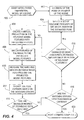
- Figure 4 is a flowchart illustrating an embodiment of the present invention to accurately estimate the pose of an image of a scene using a three dimensional model of the scene.
- Figure 5 is a flowchart illustrating an embodiment of the present invention to update a three dimensional model of a scene using an image of the scene with an unknown pose.
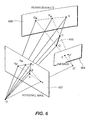
- Figure 6 is a perspective drawing illustrating the use of epipolar geometry to determine the relative pose of two images.
- Figure 7 is a flowchart illustrating an embodiment of the present invention to update a three dimensional model of a scene using a pair of images of the scene with unknown poses.
- Figure 8 is a top plan drawing illustrating a remote vehicle with a mounted camera viewing the scene from Figure 1.
- Figure 9 is a flowchart illustrating an embodiment of the present invention to accurately estimate the position of a remote vehicle within a scene using a three dimensional model of the scene and an image of the scene.
- Figure 10 is a perspective drawing of a surface from Figure 2 illustrating the separation of the surface into approximately equal sized portions used in an exemplary hybrid three dimensional model according to the present invention.
- Figure 11 is a flowchart illustrating an embodiment of the present invention to create a hybrid three-dimensional model of a scene.
- Figure 12 is a perspective drawing of a scene illustrating an exemplary video flashlight method of the present invention.
- Figure 13 is a flowchart illustrating an embodiment of the present invention to create virtual images of a scene and a dynamic three-dimensional model of the scene using a video flashlight method.
- the present invention embodies systems and methods for processing one or more video streams, for the purposes of progressively constructing and refining a 3D-scene model, geolocating objects, and enhanced visualization of dynamic scenes.
- One embodiment of the present invention is a progressive strategy to model construction and refinement, starting with a coarse model and incrementally refining it with information derived from freely moving video cameras, thereby increasing the spatial fidelity and temporal currentness of the model.
- Figure 1 is a top plan drawing showing several cameras 108, which may be stationary or may be in motion.
- the cameras view an exemplary scene 100, containing three objects, cube 102, star prism 104, and cylinder 106.
- Figure 2 is a perspective drawing of an exemplary polyhedral model of scene 100 from Figure 1. All objects in this model are all represented as polyhedra composed of planar polygonal surfaces 200, even a curved object, such as cylinder 106. To accomplish such a polyhedral representation, the modeled representation of cylinder 106 contains artificial edge boundaries 204. Also shown in Figure 2 are dotted lines 202, which represent edge boundaries that are hidden in the illustrated view of the model. While this model is shown as an image of a physical scene, it is contemplated that the model may be a mathematical representation of the scene, stored in a data file.
- a first exemplary embodiment of the present invention is a method of automatic pose estimation and registration of video to an existing polyhedral scene model, which may or may not have texture information suitable for registration.
- the method of this embodiment may be used to estimate camera pose with respect to textured or untextured models, by optimizing the fit between line segments projected from model to image and the gradients of image intensity. This method may be combined with interframe prediction to continuously track a video stream.
- Figure 4 is a flowchart illustrating this exemplary embodiment of the present invention.
- the method begins with a three dimensional model of the scene, 400, such as that shown in Figure 2.
- the first step, 402 is to generate an initial, rough estimate of the pose of an image by comparing the image to the three dimension model of the scene. Numerous methods may be used to obtain this initial estimate.
- a user can set the pose for the first frame. Physical measurements from position/attitude sensors mounted on the camera platform may be another source.
- the estimated pose of the previous frame may be used as the initial pose, or the pose can be predicted from the previous frame's estimated pose based on assumed motion. Interframe alignment may also be used to assist with prediction and with overcoming ambiguity.
- One method for determining an initial pose estimate may be to extract corresponding 2D feature points from a pair of successive images using an optical flow technique.
- flow estimation may be initialized with the 2D projective motion field estimated by a global parametric motion algorithm. Methods for flow estimation of this type are described in U.S. Patent number 5,629,988 , entitled "SYSTEM AND METHOD FOR ELECTRONIC IMAGE STABILIZATION".
- each selected feature point is mapped into its corresponding 3D point in the world view by using the current estimated pose and the current shape model.
- the initial pose estimate is then determined from the set of 3D and 2D correspondences. This may be done, for example, using the Random Sample Consensus (RANSAC) method of robust least squares fitting.
- RANSAC Random Sample Consensus
- the existing model may be considered a collection of untextured polygonal faces. Face edges in the model imply discontinuities in surface normal and/or material properties in the actual 3D scene, which generally induce brightness edges in an image. Although the subject invention is described in terms of brightness edges, it is contemplated that other types of edges may be used such as those defined by changes in color or texture on an appropriately colored and/or textured model. Because they are relatively easy to identify, an exemplary alignment method selects 3D line segments from the model as relevant features.
- Figure 3 is a drawing illustrating selection of relevant features 302 from the polyhedral model of Figure 2.
- Figure 3 is drawn to have the same pose as that used for the perspective drawing of Figure 2.
- occluded fragments of model features, dotted lines 202 in Figure 2 may be deleted by known methods, such as a Z-buffer hidden line removal process.
- multiple local minima in pose estimation may be caused by closely spaced edges in either the model or the image even if they correspond to brightness edges in the image. Therefore, once the possible relevant features of the model have been identified, a projection of these features as they appear in the estimated pose is created, step 406 in Figure 4, and projected model features are culled out if any similarly oriented projected model edge lies near it. Projected model features may also be culled if image texture analysis reveals the presence of multiple image edges within a predetermined distance. This culling may be dynamically adapted to the current level of uncertainty, so that as pose becomes better known, more edges can be included for increased pose estimation accuracy.
- Application-dependent heuristics for this culling may be applied, for example, keeping only model edges common to exactly two faces, keeping edges only at large dihedral angles, ignoring edges which are too close together, and ignoring edges near and on the ground (terrain faces may be annotated in the given model).
- the dotted lines 300 represent features which have been ignored in this exemplary pose as too close to other lines. Also missing are the artificial edge boundaries 204 from the model shown in Figure 2, as the their dihedral angles have been determined to be too small.
- step 418 based on the change in the estimated pose in the exemplary method of Figure 4, is shown as step 418. If the pose of the camera has changed by more than a threshold amount since the features were selected from the model, step 418 jumps to step 404 to select a new set of features.
- the process of pose refinement desirably leads toward smaller changes in the estimated pose. Therefore, often the estimate of pose will quickly become approximately correct. In this instance, step 418 branches to step 406 and same set of relevant features will be used throughout the remaining pose refinement.
- the virtual projection of the relevant features is matched to brightness features in the image, step 408. Additionally, color and/or texture edges may be used to generate image features, not just brightness edges. Matching errors are generated to indicate the goodness of the fit, step 410. The estimated pose is then updated based on these matching errors, step 412.
- the matching error calculation may be accomplished by many methods, including a number of image processing methods used for image warping and mosaic construction.
- One exemplary method is to use any of a number of discrete search schemes. Perturbing the pose estimate, either at the initial estimate, step 402, or during refinement, step 412, is one method that may increase the likelihood of finding the global minimum. These perturbations in pose estimate may be generated by explicitly perturbing the pose parameters. Alternatively, they may be generated in a data-driven fashion, as in RANSAC, wherein pose hypotheses are estimated from many randomly chosen subsets of the model features.
- interframe registration may be used to yield constraints on relative poses of neighboring frames, which, in turn, may allow poses of a collection of frames to be determined unambiguously. If a set of nearby frames collectively views a larger set of edges than any single frame, simultaneously exploiting image-to-model constraints in multiple frames may help to disambiguate pose.
- An exemplary embodiment of the present invention aligns the three dimensional model to a mosaic, virtual wide-angle image, from a virtual rigid rig of cameras. Suppose that a pose estimate has been predicted for one frame, but that this pose estimate is ambiguous due to a paucity of relevant model edges. For each of the remaining frames, interframe prediction may be used to obtain pose estimates. These pose estimates may then be treated as a virtual rigid rig of cameras. The total image-to-model error of the mosaic, virtual wide-angle image, created from these frames is then minimized. This method is particularly useful for scenes in which the features are relatively static.
- Mismatched features may also occur because the attributes being measured are not sufficiently discriminating.
- a projected model feature may be matched equally well to an image edge of equal length, an image edge of longer length, or a series of short image edges.
- Many different methods for matching image features tuned to scale and orientation are known in the art.
- One method that may be used is pyramid processing. Both the image and the model may be processed into a pyramid of resolution levels. As the estimated pose becomes more accurate (i.e. the matching errors decrease), the resolution level, and number of features retained, may be increased.
- the matching errors may also be optimized with respect to the estimated pose via steepest descent.
- the current pose estimate may be iteratively incremented by moving in the gradient direction in the space of an orthogonalized incremental pose parameter. In that space, a unit step in any direction causes the RMS change in line segment points of image features to be 1 pixel.
- One of the properties that may be desirable for the matching errors is a degree of robustness against outliers. Desirably this robustness includes both poorly fitting lines and model clutter, i.e. a spurious model feature that has no true matching image feature. If the projected feature lies far from any image feature, it contributes little to the calculation of the gradient of estimated pose. To reduce the chance that a projected model line segment, whether an artifact of model clutter or a valid feature, would be attracted to a falsely matching image feature, dissimilarly oriented model and image edges may be ignored by using an oriented energy image tuned to the angle of the model line.
- an oriented energy image including the oriented energy at a selected angle may be computed as follows.
- the source image is differentiated in the selected direction and smoothed in a perpendicular direction.
- the magnitude of the latter is smoothed in the selected direction.
- This method responds to both step edges and impulses.
- the orientation may be quantized to multiples of 45° and scaled to powers of 2, as in a pyramid.
- orientation tuning may be very broad in the oriented energy pyramid described above.
- the solution may be to add more discriminating feature attributes to the representation.
- the measure of the matching errors may be improved, for example, by using sharper orientation tuning.
- the camera may only see a small part of the model at a time.
- One method to overcome this difficulty is to combine several images to form a mosaic that is warped to the coordinate system of the current image. This composite image may be used in the algorithm, in place of the individual image, to determine the pose of the camera at the position of the current image.
- Figure 5 is a flowchart illustrating an embodiment of the present invention to update a three dimensional model of a scene using an image of the scene with an unknown pose.
- This method begins with several steps that are similar to those described above with regard to Figure 4.
- the embodiment illustrating in Figure 5 begins with a three dimensional model of the scene, 500.
- This starting model may be very rudimentary and limited in its scope. As images are aligned and information from these images used to update the model, the detail and range of the model may both be increased.
- step 512 may query if the matching score exceeds a predetermined level.
- Step 514 determines whether the pose estimate indicates that the pose of the camera has changed so much from the initial pose in which the current relevant features were selected that it may be desirable to reselect a new set of relevant model features to be used for continued pose refinement.
- the data from the image is used to update the three dimensional model, step 516.
- This update may include: the refinement of object placement within the scene; the additions of textural or fine structural detail to surfaces of objects; temporal updating of dynamic processes, such as changing illumination, or objects in motion; and the spatial extension of the scene being modeled.
- a number of methods to project image data onto a corresponding three dimensional model, such as a simple ray tracing method, are known in the art and may be used in step 516. For many of these methods it is desirable to use two, or more, images simultaneously, particularly to assist with refining object placement and identifying objects in motion.
- Figure 6 is a perspective drawing illustrating a plane in the scene, 600, and the poses of two images, 602 and 604, of the scene, both of which include object 606.
- the epipolar geometry shown in Figure 6 for image processing and mosaic construction.
- the epipole is shown as the line O-O'.
- the epipolar geometry of a scene may also be used to place constraints on the relative pose of images 602 and 604 even if the location of object 606 within the scene is not known.
- plane plus parallax methods may be used to generate relative pose constraints between images. A detailed discussion of some of these methods is provided in U.S. Patent number 6,192,145 , entitled “METHOD AND APPARATUS FOR THREE-DIMENSIONAL SCENE PROCESSING USING PARALLAX GEOMETRY OF PAIRS OF POINTS”.
- Figure 7 is a flowchart illustrating another exemplary embodiment of the present invention. This exemplary method is similar to that previously described with regard to Figure 5, but uses multiple images of the scene with unknown poses to update a three dimensional model of a scene. Although the exemplary method shown in Figure 7 only employs two images at a time, it is contemplated that three or more images may be simultaneously used in this embodiment. The images may be successive images from a moving source, or they may be concurrently generated images from multiple sources.
- the parallel paths in Figure 7, such as steps 702 and 704 represent parallel processes, which may occurs as multi-threaded tasks within the image processing hardware of the present invention. It may be desirable for these tasks to be performed concurrently by parallel processors to increase processing speed.
- this embodiment begins with a three dimension model of a scene, 700, and the first and second images are compared to the three dimensional model of the scene, steps 702 and 704 respectively, to generate pose estimates.
- pose estimates may be initial pose estimates, or may be refined as described in previous embodiments of the present invention. If the pose estimated are refined, it may be desirable for the matching error criteria to be less precise than in previous embodiments.
- the first and second image are compared to one another, step 706, to generate constraints on the relative poses of the two images.
- the pose estimates are then updated to accommodate the relative pose constraints, step 708. While it is often desirable to minimize the individual image to model mismatches when the pose estimates are being updated, this update should result in pose estimates that fit within the relative pose constraints generated in step 706.
- sets of relevant features from the three dimensional model, corresponding to the first image and the second image are selected based on the updated poses, steps 710 and 712 respectively. These sets of relevant features may be selected by any of the previously disclosed methods.
- the corresponding set of relevant features is next projected to the estimated pose of the first image, matched to the first image and first image matching errors are measured, step 714. The same procedure is followed for the second image in step 716.
- the three dimensional model is updated using the matching errors from both images to improve the position estimate of objects within the model, step 718.
- the matching errors are jointly minimized with respect to position estimate for both images to refine the placement of known objects in the scene model. Further iterations may be used to improve the model refinement, and possibly the estimated camera poses as well. These iterations may start by once again estimating the image poses, steps 702 and 704, or with the selection of sets of relevant model features, steps 710 and 712.
- parameters may be estimated jointly in multiple frames, akin to bundle adjustment in structure from motion.
- inconsistency of poses with respect to interframe alignments should also be penalized, e.g. uncertainties in the relative pose constraints of corresponding points in frame pairs may be used to weight the importance of matching errors for various images.
- refinement of object placement may be extended to more general deformations by using an additional set of parameters to describe known sizes and relationships of parts of objects.
- FIGs 8 and 9 One possible use of the present invention is illustrated in Figures 8 and 9.
- This application of the present invention involves using current video from a camera mounted on a remote vehicle to locate the vehicle relative to objects in a three dimensional model.
- An additional application for the present invention may be to extend and refine a three dimensional model of an area as the area is explored by the remote vehicle possibly beyond the range of the scene originally covered by the model.
- Figure 8 is a top plan drawing of remote vehicle 800, with mounted camera 802, viewing the scene from Figure 1.
- the camera is turned so that at least a portion of each object in the scene, cube 102, star prism 104, and cylinder 106, is visible (shown as surfaces 804).
- surfaces 804 show surfaces 804
- both the remote vehicle and the camera may be independently moveable, the position and angular orientation of camera 802 relative to remote vehicle 800 are assumed to be known, or at least measurable.
- Figure 9 is a flowchart illustrating an exemplary embodiment of the present invention to accurately estimate the position of a remote vehicle within a scene using a three dimensional model of the scene and an image of the scene.
- the method begins with a three dimension model and an image from a camera having an orientation relative to the remote vehicle, 900 that can be determined.
- the next seven steps, 902, 904, 906, 908, 910, 912, and 914, involve estimating and refining the camera pose with respect to the three dimensional model. These steps are the same as steps 502, 504, 506, 508, 510, 512, and 514 in the flowchart of Figure 5.
- the position and orientation of the remote vehicle relative to the scene in the three dimensional model may be determined, step 916. Because the mounted camera may be adjusted to rotate, tilt or zoom, parameters controlling these functions may need to be examined to determine the orientation of the camera relative to the remote vehicle.
- the pose of the camera may be used independently of the position and orientation of the vehicle to update the model.
- the three dimensional model is updated based on data from the image and its estimated pose, step 918, similarly to step 516 in Figure 5.
- the camera orientation, and possibly its position, relative to the remote vehicle are determined, step 920 to fix the position of the vehicle. The process begins again at step 902 when another image is taken.
- an exemplary embodiment of the present invention may be used for detailed refinement of a three dimensional model, including definition of local surface shape and texture.
- the true shape of the surfaces in the scene may differ from the planar surfaces given by the given polyhedral model, even after refinement of object placement.
- the existing objects may have changed, and objects may be added or deleted.
- Some scene objects, especially natural objects like trees, may be absent from the model, or unsatisfactorily represented, because they are hard to represent using simple polyhedra. This can be clearly seen for the polyhedral model of cylinder 106 in Figure 2.
- an untextured model such as the previous mentioned polyhedral model
- the brightness of an object in the scene may be approximated as being constant, independent of the viewpoint, and each surface pixel may be assigned a color value that is most typical of all the given images.
- polygonal surfaces of a polyhedral three-dimensional model may be separated into approximately equally sized portions. This may allow for better mapping of surface detail from a series of images onto the model, particularly for surfaces that are only partially visible in some of the images.
- Figure 10 shows a perspective drawing of surface 200, from Figure 2, which has been separated into approximately equal sized portions 1000. Surface detail 1002 for one portion, which may be added to the polyhedral model, is also shown. By adding surface detail to a polyhedral model of the scene in this manner, a hybrid three-dimensional model of the scene may be created.
- Figure 11 is a flowchart illustrating an exemplary embodiment of the present invention to create such a hybrid three dimensional model of a scene using a series of images of the scene.
- the first step is to create a polyhedral model the scene, step 1100.
- the polyhedral model desirably includes a plurality of polygonal surfaces, which are larger than a predetermined size for surface portions. Any standard technique for creating the model may be used.
- the rough shape and placement of objects in the polyhedral model may be refined according to the techniques of either of the flowcharts in Figures 5 and 7 using previous, possibly low resolution, images of the scene and/or the series of images to be employed for adding surface detail to the model. It is also important to determine the camera poses of the series of images. The poses may be known, or may be determined by one of the methods described above.
- a polygonal face is selected from the polyhedral model for determination of surface details, step 1102.
- the selection may be predetermined to sweep the analysis from one side of the model to its opposite side, or it may be based on a determination of scene areas in the images where the modeled shape appears to differ significantly from the existing model.
- the latter selection method is most useful when refinement of surface details is desirably to be performed only in those areas of the model that deviate from the images by an amount greater than a certain threshold.
- these height maps may be estimated by dense 3D estimation techniques from two or more observed images.
- the outcome of this process is a hybrid shape representation that augments the polyhedral model with local shape variation.
- the residual misalignment may be estimated, i.e. flow constrained along the epipolar lines.
- an estimation algorithm can handle a large amount of parallax, which may occur in areas of significant discrepancy between the given shape model and the actual 3D structure of the scene.
- the last step is to convert the resulting parallax magnitude to metric height.
- the estimated shape may be very accurate; however, occlusion and deocclusion areas cannot be well represented using a depth map with respect to one reference view.
- a smaller batch of images may produce a shape estimate good enough to align and synthesize viewpoints in the vicinity of the source data.
- an alternative may be to use the parallax estimation methods to independently estimate and represent shape within a series of overlapping batches of images, each with its own reference view. Each such estimate would be stored in a hybrid scene representation consisting of a polyhedral model plus view-dependent local shape variations.
- step 1104 in Figure 11 is to separate the selected polygonal surface into portions of approximately the predetermined size for surface portions. This predetermined size may be as small as a single element within the model, or it may be as large as the entire polygonal surface. Next one of these portions is selected, step 1106. Z-buffering may be used to detect and discard those images which are occluded by some other face, leaving a subset of images which contain the selected surface portion, step 1108 .
- X is mapped to every image in the subset, using object placement parameters for the surface, camera pose parameters and, if available, the previously estimated height maps.
- One method is to combine the color values from the pixels in the subset of images corresponding to X. This may be done by averaging the color values, blending the color values or performing another mathematical function on the color values of the various images in the subset.
- the color and brightness at corresponding points in different images may not be identical, due to camera gain variations and non-Lambertian surface materials. Abruptly switching between different source images while computing the appearance of a single face may cause seams to appear in the texture map. Accordingly, it may be desirable to use pixel values from a single image to map texture onto a given surface of the model, if possible.
- step 1114 any artifacts caused by using multiple images to generate the texture maps of the portions of a single surface may be mitigated through multi-resolution blending of the portions, step 1116, as taught in U.S. Patent number 6,075,905 , entitled “METHOD AND APPARATUS FOR MOSAIC IMAGE CONSTRUCTION".
- This step may also be employed when a single image is used to map texture onto all of the portions of a given surface of the model.
- the foregoing method to create a surface texture map of a hybrid three dimensional model may be used whether the scene is initially modeled by planar faces alone or by a model of planar faces plus shape variations.
- texture may be recovered for each local reference view. The result would be a 3D-scene model with view-dependent shape and texture.
- One exemplary method to synthesize a new image from a novel viewpoint may be to interpolate the shape and texture of two or more nearby reference views closest to the desired viewpoint, according to the teachings of U.S. Patent Application number 08/917402 , entitled "METHOD AND SYSTEM FOR RENDERING AND COMBINING IMAGES TO FORM A SYNTHESIZED VIEW OF A SCENE CONTAINING IMAGE INFORMATION FROM A SECOND IMAGE".
- Figure 12 is a perspective drawing of a scene, 1200, illustrating an exemplary video flashlights method of the present invention, which may be employed to synthesize an image from a novel viewpoint using a dynamic three dimensional model, such as those previously described with regard to the flowcharts of Figures 5, 7, and 11.
- the exemplary scene, 1200 is being filmed by video cameras 1202, which may be in motion. At any given time, images from these cameras contain only a portion of the scene , 1204.
- Figure 13 is a flowchart illustrating an exemplary embodiment of the present invention to create virtual images of a scene and a dynamic three-dimensional model of the scene using this video flashlight method.
- This exemplary method involves two concurrent processes. Both of these processes start from a preexisting three dimensional model of the scene, 1300. The first of these processes, updating the model using the incoming video data, is exemplified in Figure 13 as steps 1302, 1304, 1306 and 1308. Any of the methods previously described above for updating a three dimensional model may be used. This dynamic updating process is continuous, so that the model may contain the most currently available data.
- the second process is the creation of output image sequence(s) based on the dynamic three-dimensional model.
- This process involves the selection of a virtual viewpoint, step 1310, and projection of the current model onto the selected viewpoint, step 1312.
- the viewpoint selection may be controlled manually, set to track a feature, or object, in the model, or may follow a predetermined pattern.
- Projection of a three dimensional model to form an image as seen from selected point may be performed by a number of well known methods, such as Z-buffering.
- An exemplary embodiment of the present invention registers all video frames to the model so that images from several cameras at the same time instant can be projected onto the model, like flashlights illuminating the scene, which may then be rendered for any user-selected viewpoint.
- images from several cameras at the same time instant can be projected onto the model, like flashlights illuminating the scene, which may then be rendered for any user-selected viewpoint.
- it may become easy to interpret the imagery and the dynamic events taking place in all streams at once.
- the three dimensional model may be constructed to be devoid of moving objects and/or objects that are difficult to model onto polyhedra. These objects may appear in the video flashlights. In a virtual imaging system of this design, it may be desirable to make control of the video flashlight(s) responsive to movement of the virtual viewpoint(s).
- Such computer-readable media include; integrated circuits, magnetic and optical storage media, as well as audio-frequency, radio frequency, and optical carrier waves.
Landscapes
- Engineering & Computer Science (AREA)
- Physics & Mathematics (AREA)
- General Physics & Mathematics (AREA)
- Theoretical Computer Science (AREA)
- Geometry (AREA)
- Computer Graphics (AREA)
- Software Systems (AREA)
- Health & Medical Sciences (AREA)
- General Health & Medical Sciences (AREA)
- Vascular Medicine (AREA)
- Multimedia (AREA)
- Computer Vision & Pattern Recognition (AREA)
- Image Analysis (AREA)
Applications Claiming Priority (2)
| Application Number | Priority Date | Filing Date | Title |
|---|---|---|---|
| US18755700P | 2000-03-07 | 2000-03-07 | |
| EP01924119A EP1297691A2 (fr) | 2000-03-07 | 2001-03-07 | Procede d'estimation de pose et d'affinage de modele pour une representation video d'une scene tridimensionnelle |
Related Parent Applications (1)
| Application Number | Title | Priority Date | Filing Date |
|---|---|---|---|
| EP01924119A Division EP1297691A2 (fr) | 2000-03-07 | 2001-03-07 | Procede d'estimation de pose et d'affinage de modele pour une representation video d'une scene tridimensionnelle |
Publications (1)
| Publication Number | Publication Date |
|---|---|
| EP1890263A2 true EP1890263A2 (fr) | 2008-02-20 |
Family
ID=38952036
Family Applications (1)
| Application Number | Title | Priority Date | Filing Date |
|---|---|---|---|
| EP07075960A Withdrawn EP1890263A2 (fr) | 2000-03-07 | 2001-03-07 | Procédé pour l'affinement du modèle d'ADN avec estimation de pose pour la représentation vidéo d'une scène tridimensionnelle |
Country Status (1)
| Country | Link |
|---|---|
| EP (1) | EP1890263A2 (fr) |
Cited By (10)
| Publication number | Priority date | Publication date | Assignee | Title |
|---|---|---|---|---|
| EP2309225A4 (fr) * | 2008-07-01 | 2014-10-15 | Topcon Corp | Procédé de mesure de position, dispositif de mesure de position et programme associé |
| CN113436254A (zh) * | 2021-06-29 | 2021-09-24 | 杭州电子科技大学 | 一种级联解耦的位姿估计方法 |
| CN113469495A (zh) * | 2021-05-28 | 2021-10-01 | 视辰信息科技(上海)有限公司 | 一种视觉定位系统的自动化评估方法及其系统 |
| CN115294207A (zh) * | 2022-06-30 | 2022-11-04 | 南京南邮信息产业技术研究院有限公司 | 智慧校园监控视频与三维gis模型的融合调度系统及方法 |
| CN115424149A (zh) * | 2022-07-25 | 2022-12-02 | 国网山东省电力公司经济技术研究院 | 一种工程进度的管理方法、系统及计算机存储介质 |
| CN115908482A (zh) * | 2022-10-14 | 2023-04-04 | 荣耀终端有限公司 | 建模错误数据的定位方法和装置 |
| WO2023085997A1 (fr) * | 2021-11-09 | 2023-05-19 | Saab Ab | Procédé, produit logiciel et système pour une navigation dépourvue de gnss |
| US11682234B2 (en) | 2020-01-02 | 2023-06-20 | Sony Group Corporation | Texture map generation using multi-viewpoint color images |
| CN116993825A (zh) * | 2023-07-21 | 2023-11-03 | 中联重科股份有限公司 | 一种姿态估计方法、装置、存储介质和电子设备 |
| CN118918273A (zh) * | 2024-10-11 | 2024-11-08 | 杭州秋果计划科技有限公司 | 基于全景图的增量式三维重建方法和装置 |
-
2001
- 2001-03-07 EP EP07075960A patent/EP1890263A2/fr not_active Withdrawn
Cited By (12)
| Publication number | Priority date | Publication date | Assignee | Title |
|---|---|---|---|---|
| EP2309225A4 (fr) * | 2008-07-01 | 2014-10-15 | Topcon Corp | Procédé de mesure de position, dispositif de mesure de position et programme associé |
| US11682234B2 (en) | 2020-01-02 | 2023-06-20 | Sony Group Corporation | Texture map generation using multi-viewpoint color images |
| CN113469495A (zh) * | 2021-05-28 | 2021-10-01 | 视辰信息科技(上海)有限公司 | 一种视觉定位系统的自动化评估方法及其系统 |
| CN113436254A (zh) * | 2021-06-29 | 2021-09-24 | 杭州电子科技大学 | 一种级联解耦的位姿估计方法 |
| CN113436254B (zh) * | 2021-06-29 | 2022-07-05 | 杭州电子科技大学 | 一种级联解耦的位姿估计方法 |
| WO2023085997A1 (fr) * | 2021-11-09 | 2023-05-19 | Saab Ab | Procédé, produit logiciel et système pour une navigation dépourvue de gnss |
| CN115294207A (zh) * | 2022-06-30 | 2022-11-04 | 南京南邮信息产业技术研究院有限公司 | 智慧校园监控视频与三维gis模型的融合调度系统及方法 |
| CN115424149A (zh) * | 2022-07-25 | 2022-12-02 | 国网山东省电力公司经济技术研究院 | 一种工程进度的管理方法、系统及计算机存储介质 |
| CN115908482A (zh) * | 2022-10-14 | 2023-04-04 | 荣耀终端有限公司 | 建模错误数据的定位方法和装置 |
| CN115908482B (zh) * | 2022-10-14 | 2023-10-20 | 荣耀终端有限公司 | 建模错误数据的定位方法和装置 |
| CN116993825A (zh) * | 2023-07-21 | 2023-11-03 | 中联重科股份有限公司 | 一种姿态估计方法、装置、存储介质和电子设备 |
| CN118918273A (zh) * | 2024-10-11 | 2024-11-08 | 杭州秋果计划科技有限公司 | 基于全景图的增量式三维重建方法和装置 |
Similar Documents
| Publication | Publication Date | Title |
|---|---|---|
| US6985620B2 (en) | Method of pose estimation and model refinement for video representation of a three dimensional scene | |
| US7085409B2 (en) | Method and apparatus for synthesizing new video and/or still imagery from a collection of real video and/or still imagery | |
| Akbarzadeh et al. | Towards urban 3d reconstruction from video | |
| CN103988226B (zh) | 用于估计摄像机运动以及用于确定实境三维模型的方法 | |
| Pollefeys et al. | Image-based 3D acquisition of archaeological heritage and applications | |
| Lin et al. | Development of a virtual reality GIS using stereo vision | |
| KR20150013709A (ko) | 컴퓨터 생성된 3d 객체들 및 필름 카메라로부터의 비디오 공급을 실시간으로 믹싱 또는 합성하기 위한 시스템 | |
| WO2014048475A1 (fr) | Procédé de détermination de la position et de l'orientation d'un dispositif associé à un dispositif de capture pour capturer au moins une image | |
| Meilland et al. | A spherical robot-centered representation for urban navigation | |
| Kumar et al. | Pose estimation, model refinement, and enhanced visualization using video | |
| Pirchheim et al. | Homography-based planar mapping and tracking for mobile phones | |
| EP1890263A2 (fr) | Procédé pour l'affinement du modèle d'ADN avec estimation de pose pour la représentation vidéo d'une scène tridimensionnelle | |
| Asai et al. | 3D modeling of outdoor environments by integrating omnidirectional range and color images | |
| Koch et al. | Wide-area egomotion estimation from known 3d structure | |
| Se et al. | Instant scene modeler for crime scene reconstruction | |
| Lhuillier | Toward flexible 3d modeling using a catadioptric camera | |
| Berger et al. | Mixing synthetic and video images of an outdoor urban environment | |
| Grzeszczuk et al. | Creating compact architectural models by geo-registering image collections | |
| Kumar et al. | 3D manipulation of motion imagery | |
| Park et al. | Hand-held 3D scanning based on coarse and fine registration of multiple range images | |
| Cheng et al. | Texture mapping 3d planar models of indoor environments with noisy camera poses | |
| Ng et al. | Generalized multiple baseline stereo and direct virtual view synthesis using range-space search, match, and render | |
| HK1114445A (en) | Method of pose estimation and model refinement for video representation of a three dimensional scene | |
| Rawlinson | Design and implementation of a spatially enabled panoramic virtual reality prototype | |
| Naikal et al. | Image augmented laser scan matching for indoor localization |
Legal Events
| Date | Code | Title | Description |
|---|---|---|---|
| PUAI | Public reference made under article 153(3) epc to a published international application that has entered the european phase |
Free format text: ORIGINAL CODE: 0009012 |
|
| 17P | Request for examination filed |
Effective date: 20071207 |
|
| AC | Divisional application: reference to earlier application |
Ref document number: 1297691 Country of ref document: EP Kind code of ref document: P |
|
| AK | Designated contracting states |
Kind code of ref document: A2 Designated state(s): DE FR GB NL |
|
| RIN1 | Information on inventor provided before grant (corrected) |
Inventor name: SAWHNEY, HARPREET SINGH Inventor name: KUMAR, RAKESH Inventor name: HSU, STEVE Inventor name: SAMARASEKERA, SUPUN |
|
| RIN1 | Information on inventor provided before grant (corrected) |
Inventor name: SAMARASEKERA, SUPUN Inventor name: NISTER, DAVID Inventor name: HSU, STEVE Inventor name: ARPA, AYDIN Inventor name: SAWHNEY, HARPREET SINGH Inventor name: HANNA, KEITH Inventor name: KUMAR, RAKESH Inventor name: AGGARWAL, MANOJ |
|
| REG | Reference to a national code |
Ref country code: HK Ref legal event code: DE Ref document number: 1114445 Country of ref document: HK |
|
| RIN1 | Information on inventor provided before grant (corrected) |
Inventor name: NISTER, DAVID Inventor name: ARPA, AYDIN Inventor name: HSU, STEVE Inventor name: SAMARASEKERA, SUPUN Inventor name: KUMAR, RAKESH Inventor name: SAWHNEY, HARPREET SINGH Inventor name: AGGARWAL, MANOJ Inventor name: HANNA, KEITH |
|
| STAA | Information on the status of an ep patent application or granted ep patent |
Free format text: STATUS: THE APPLICATION HAS BEEN WITHDRAWN |
|
| 18W | Application withdrawn |
Effective date: 20100616 |
|
| REG | Reference to a national code |
Ref country code: HK Ref legal event code: WD Ref document number: 1114445 Country of ref document: HK |