EP1890370A2 - Überwachung der Batteriezellenspannung - Google Patents
Überwachung der Batteriezellenspannung Download PDFInfo
- Publication number
- EP1890370A2 EP1890370A2 EP07016156A EP07016156A EP1890370A2 EP 1890370 A2 EP1890370 A2 EP 1890370A2 EP 07016156 A EP07016156 A EP 07016156A EP 07016156 A EP07016156 A EP 07016156A EP 1890370 A2 EP1890370 A2 EP 1890370A2
- Authority
- EP
- European Patent Office
- Prior art keywords
- switch
- voltage
- threshold
- voltage detection
- battery cell
- Prior art date
- Legal status (The legal status is an assumption and is not a legal conclusion. Google has not performed a legal analysis and makes no representation as to the accuracy of the status listed.)
- Withdrawn
Links
Images


Classifications
-
- H—ELECTRICITY
- H01—ELECTRIC ELEMENTS
- H01M—PROCESSES OR MEANS, e.g. BATTERIES, FOR THE DIRECT CONVERSION OF CHEMICAL ENERGY INTO ELECTRICAL ENERGY
- H01M10/00—Secondary cells; Manufacture thereof
- H01M10/42—Methods or arrangements for servicing or maintenance of secondary cells or secondary half-cells
- H01M10/48—Accumulators combined with arrangements for measuring, testing or indicating the condition of cells, e.g. the level or density of the electrolyte
- H01M10/482—Accumulators combined with arrangements for measuring, testing or indicating the condition of cells, e.g. the level or density of the electrolyte for several batteries or cells simultaneously or sequentially
-
- G—PHYSICS
- G01—MEASURING; TESTING
- G01R—MEASURING ELECTRIC VARIABLES; MEASURING MAGNETIC VARIABLES
- G01R19/00—Arrangements for measuring currents or voltages or for indicating presence or sign thereof
- G01R19/165—Indicating that current or voltage is either above or below a predetermined value or within or outside a predetermined range of values
- G01R19/16533—Indicating that current or voltage is either above or below a predetermined value or within or outside a predetermined range of values characterised by the application
- G01R19/16538—Indicating that current or voltage is either above or below a predetermined value or within or outside a predetermined range of values characterised by the application in AC or DC supplies
- G01R19/16542—Indicating that current or voltage is either above or below a predetermined value or within or outside a predetermined range of values characterised by the application in AC or DC supplies for batteries
-
- G—PHYSICS
- G01—MEASURING; TESTING
- G01R—MEASURING ELECTRIC VARIABLES; MEASURING MAGNETIC VARIABLES
- G01R31/00—Arrangements for testing electric properties; Arrangements for locating electric faults; Arrangements for electrical testing characterised by what is being tested not provided for elsewhere
- G01R31/36—Arrangements for testing, measuring or monitoring the electrical condition of accumulators or electric batteries, e.g. capacity or state of charge [SoC]
- G01R31/396—Acquisition or processing of data for testing or for monitoring individual cells or groups of cells within a battery
-
- H—ELECTRICITY
- H01—ELECTRIC ELEMENTS
- H01M—PROCESSES OR MEANS, e.g. BATTERIES, FOR THE DIRECT CONVERSION OF CHEMICAL ENERGY INTO ELECTRICAL ENERGY
- H01M10/00—Secondary cells; Manufacture thereof
- H01M10/42—Methods or arrangements for servicing or maintenance of secondary cells or secondary half-cells
- H01M10/425—Structural combination with electronic components, e.g. electronic circuits integrated to the outside of the casing
-
- H—ELECTRICITY
- H01—ELECTRIC ELEMENTS
- H01M—PROCESSES OR MEANS, e.g. BATTERIES, FOR THE DIRECT CONVERSION OF CHEMICAL ENERGY INTO ELECTRICAL ENERGY
- H01M8/00—Fuel cells; Manufacture thereof
- H01M8/04—Auxiliary arrangements, e.g. for control of pressure or for circulation of fluids
- H01M8/04298—Processes for controlling fuel cells or fuel cell systems
- H01M8/04313—Processes for controlling fuel cells or fuel cell systems characterised by the detection or assessment of variables; characterised by the detection or assessment of failure or abnormal function
- H01M8/04537—Electric variables
- H01M8/04544—Voltage
- H01M8/04552—Voltage of the individual fuel cell
-
- H—ELECTRICITY
- H02—GENERATION; CONVERSION OR DISTRIBUTION OF ELECTRIC POWER
- H02J—ELECTRIC POWER NETWORKS; CIRCUIT ARRANGEMENTS OR SYSTEMS FOR SUPPLYING OR DISTRIBUTING ELECTRIC POWER; SYSTEMS FOR STORING ELECTRIC ENERGY
- H02J7/00—Circuit arrangements for charging or discharging batteries or for supplying loads from batteries
- H02J7/50—Circuit arrangements for charging or discharging batteries or for supplying loads from batteries acting upon multiple batteries simultaneously or sequentially
-
- H—ELECTRICITY
- H02—GENERATION; CONVERSION OR DISTRIBUTION OF ELECTRIC POWER
- H02J—ELECTRIC POWER NETWORKS; CIRCUIT ARRANGEMENTS OR SYSTEMS FOR SUPPLYING OR DISTRIBUTING ELECTRIC POWER; SYSTEMS FOR STORING ELECTRIC ENERGY
- H02J7/00—Circuit arrangements for charging or discharging batteries or for supplying loads from batteries
- H02J7/80—Circuit arrangements for charging or discharging batteries or for supplying loads from batteries including monitoring or indicating arrangements
- H02J7/82—Control of state of charge [SOC]
-
- H—ELECTRICITY
- H02—GENERATION; CONVERSION OR DISTRIBUTION OF ELECTRIC POWER
- H02J—ELECTRIC POWER NETWORKS; CIRCUIT ARRANGEMENTS OR SYSTEMS FOR SUPPLYING OR DISTRIBUTING ELECTRIC POWER; SYSTEMS FOR STORING ELECTRIC ENERGY
- H02J7/00—Circuit arrangements for charging or discharging batteries or for supplying loads from batteries
- H02J7/80—Circuit arrangements for charging or discharging batteries or for supplying loads from batteries including monitoring or indicating arrangements
- H02J7/84—Control of state of health [SOH]
-
- H—ELECTRICITY
- H01—ELECTRIC ELEMENTS
- H01M—PROCESSES OR MEANS, e.g. BATTERIES, FOR THE DIRECT CONVERSION OF CHEMICAL ENERGY INTO ELECTRICAL ENERGY
- H01M10/00—Secondary cells; Manufacture thereof
- H01M10/42—Methods or arrangements for servicing or maintenance of secondary cells or secondary half-cells
- H01M10/44—Methods for charging or discharging
-
- H—ELECTRICITY
- H01—ELECTRIC ELEMENTS
- H01M—PROCESSES OR MEANS, e.g. BATTERIES, FOR THE DIRECT CONVERSION OF CHEMICAL ENERGY INTO ELECTRICAL ENERGY
- H01M2250/00—Fuel cells for particular applications; Specific features of fuel cell system
- H01M2250/20—Fuel cells in motive systems, e.g. vehicle, ship, plane
-
- H—ELECTRICITY
- H01—ELECTRIC ELEMENTS
- H01M—PROCESSES OR MEANS, e.g. BATTERIES, FOR THE DIRECT CONVERSION OF CHEMICAL ENERGY INTO ELECTRICAL ENERGY
- H01M2250/00—Fuel cells for particular applications; Specific features of fuel cell system
- H01M2250/30—Fuel cells in portable systems, e.g. mobile phone, laptop
-
- H—ELECTRICITY
- H01—ELECTRIC ELEMENTS
- H01M—PROCESSES OR MEANS, e.g. BATTERIES, FOR THE DIRECT CONVERSION OF CHEMICAL ENERGY INTO ELECTRICAL ENERGY
- H01M8/00—Fuel cells; Manufacture thereof
- H01M8/04—Auxiliary arrangements, e.g. for control of pressure or for circulation of fluids
- H01M8/04298—Processes for controlling fuel cells or fuel cell systems
- H01M8/04313—Processes for controlling fuel cells or fuel cell systems characterised by the detection or assessment of variables; characterised by the detection or assessment of failure or abnormal function
- H01M8/0432—Temperature; Ambient temperature
- H01M8/04365—Temperature; Ambient temperature of other components of a fuel cell or fuel cell stacks
-
- H—ELECTRICITY
- H01—ELECTRIC ELEMENTS
- H01M—PROCESSES OR MEANS, e.g. BATTERIES, FOR THE DIRECT CONVERSION OF CHEMICAL ENERGY INTO ELECTRICAL ENERGY
- H01M8/00—Fuel cells; Manufacture thereof
- H01M8/04—Auxiliary arrangements, e.g. for control of pressure or for circulation of fluids
- H01M8/04298—Processes for controlling fuel cells or fuel cell systems
- H01M8/04313—Processes for controlling fuel cells or fuel cell systems characterised by the detection or assessment of variables; characterised by the detection or assessment of failure or abnormal function
- H01M8/04664—Failure or abnormal function
- H01M8/04671—Failure or abnormal function of the individual fuel cell
-
- Y—GENERAL TAGGING OF NEW TECHNOLOGICAL DEVELOPMENTS; GENERAL TAGGING OF CROSS-SECTIONAL TECHNOLOGIES SPANNING OVER SEVERAL SECTIONS OF THE IPC; TECHNICAL SUBJECTS COVERED BY FORMER USPC CROSS-REFERENCE ART COLLECTIONS [XRACs] AND DIGESTS
- Y02—TECHNOLOGIES OR APPLICATIONS FOR MITIGATION OR ADAPTATION AGAINST CLIMATE CHANGE
- Y02B—CLIMATE CHANGE MITIGATION TECHNOLOGIES RELATED TO BUILDINGS, e.g. HOUSING, HOUSE APPLIANCES OR RELATED END-USER APPLICATIONS
- Y02B90/00—Enabling technologies or technologies with a potential or indirect contribution to GHG emissions mitigation
- Y02B90/10—Applications of fuel cells in buildings
-
- Y—GENERAL TAGGING OF NEW TECHNOLOGICAL DEVELOPMENTS; GENERAL TAGGING OF CROSS-SECTIONAL TECHNOLOGIES SPANNING OVER SEVERAL SECTIONS OF THE IPC; TECHNICAL SUBJECTS COVERED BY FORMER USPC CROSS-REFERENCE ART COLLECTIONS [XRACs] AND DIGESTS
- Y02—TECHNOLOGIES OR APPLICATIONS FOR MITIGATION OR ADAPTATION AGAINST CLIMATE CHANGE
- Y02E—REDUCTION OF GREENHOUSE GAS [GHG] EMISSIONS, RELATED TO ENERGY GENERATION, TRANSMISSION OR DISTRIBUTION
- Y02E60/00—Enabling technologies; Technologies with a potential or indirect contribution to GHG emissions mitigation
- Y02E60/10—Energy storage using batteries
-
- Y—GENERAL TAGGING OF NEW TECHNOLOGICAL DEVELOPMENTS; GENERAL TAGGING OF CROSS-SECTIONAL TECHNOLOGIES SPANNING OVER SEVERAL SECTIONS OF THE IPC; TECHNICAL SUBJECTS COVERED BY FORMER USPC CROSS-REFERENCE ART COLLECTIONS [XRACs] AND DIGESTS
- Y02—TECHNOLOGIES OR APPLICATIONS FOR MITIGATION OR ADAPTATION AGAINST CLIMATE CHANGE
- Y02E—REDUCTION OF GREENHOUSE GAS [GHG] EMISSIONS, RELATED TO ENERGY GENERATION, TRANSMISSION OR DISTRIBUTION
- Y02E60/00—Enabling technologies; Technologies with a potential or indirect contribution to GHG emissions mitigation
- Y02E60/30—Hydrogen technology
- Y02E60/50—Fuel cells
-
- Y—GENERAL TAGGING OF NEW TECHNOLOGICAL DEVELOPMENTS; GENERAL TAGGING OF CROSS-SECTIONAL TECHNOLOGIES SPANNING OVER SEVERAL SECTIONS OF THE IPC; TECHNICAL SUBJECTS COVERED BY FORMER USPC CROSS-REFERENCE ART COLLECTIONS [XRACs] AND DIGESTS
- Y02—TECHNOLOGIES OR APPLICATIONS FOR MITIGATION OR ADAPTATION AGAINST CLIMATE CHANGE
- Y02T—CLIMATE CHANGE MITIGATION TECHNOLOGIES RELATED TO TRANSPORTATION
- Y02T10/00—Road transport of goods or passengers
- Y02T10/60—Other road transportation technologies with climate change mitigation effect
- Y02T10/70—Energy storage systems for electromobility, e.g. batteries
-
- Y—GENERAL TAGGING OF NEW TECHNOLOGICAL DEVELOPMENTS; GENERAL TAGGING OF CROSS-SECTIONAL TECHNOLOGIES SPANNING OVER SEVERAL SECTIONS OF THE IPC; TECHNICAL SUBJECTS COVERED BY FORMER USPC CROSS-REFERENCE ART COLLECTIONS [XRACs] AND DIGESTS
- Y02—TECHNOLOGIES OR APPLICATIONS FOR MITIGATION OR ADAPTATION AGAINST CLIMATE CHANGE
- Y02T—CLIMATE CHANGE MITIGATION TECHNOLOGIES RELATED TO TRANSPORTATION
- Y02T90/00—Enabling technologies or technologies with a potential or indirect contribution to GHG emissions mitigation
- Y02T90/40—Application of hydrogen technology to transportation, e.g. using fuel cells
Definitions
- This disclosure relates to voltage monitoring, and more particularly, to monitoring battery cells in a battery pack.
- Some electrical devices such as power tools, electrical vehicles and other portable devices may be powered by battery packs.
- a cordless battery pack By attaching a cordless battery pack to a power tool, a user is free to move about without being constrained by a power cord.
- a battery pack may include battery cells and switching circuitry for allowing the battery cells to supply power or be charged.
- One or more monitoring functions may be performed by circuitry included in the battery pack to maintain a safe use of the battery cells. For example, the voltage levels present on each battery cell may be monitored.
- Certain battery cell chemistries e.g., lithium-ion cells, may become hazardous if their voltage level exceeds a high voltage threshold or drops below a low voltage threshold. Accordingly, conventional circuitries may monitor battery cell voltage and compare the monitored voltage to predefined low and high voltage thresholds. If either threshold is reached, a safety function (e.g., increase monitoring rate, open a switch, etc.) may be initiated. However, determining that a threshold breech may take a considerable period of time, and such a long period of time may exceed safety limits of the battery.
- a safety function e.g., increase monitoring rate, open a switch, etc.
- a monitoring circuitry for monitoring battery cell voltages.
- the monitoring circuitry includes a plurality of voltage detection paths and a logic device.
- Each voltage detection path is coupled to a battery cell and is operable for comparing a cell voltage of the battery cell with a switch threshold of a switch.
- Each voltage detection path is ON if the cell voltage is greater than the switch threshold.
- the logic device is coupled to the plurality of voltage detection paths. According to a conductance status of each voltage detection path, the logic device generates an alert signal.
- FIG. 1 illustrates a diagrammatic view of a power tool that includes a battery pack, in accordance with one embodiment of the present invention.
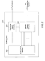
- FIG. 2 illustrates an exemplary block diagram that represents portions of the battery pack shown in FIG.1, in accordance with one embodiment of the present invention.
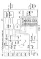
- FIG. 3 illustrates an exemplary block diagram that represents an exemplary gas gauge circuitry that monitors the voltage levels present on the battery cells shown in FIG. 2, in accordance with one embodiment of the present invention.
- FIG. 4 illustrates a flowchart that represents some of the operations of a controller included in the gas gauge circuitry shown in FIG. 2, in accordance with one embodiment of the present invention.
- FIG. 5 illustrates an exemplary block diagram that represents an exemplary gas gauge circuitry which includes a monitoring circuit for monitoring voltages present on the battery cells shown in FIG. 2, in accordance with one embodiment of the present invention.
- FIG. 6 illustrates another exemplary block diagram that represents an exemplary gas gauge circuitry which includes a monitoring circuit for monitoring voltages present on the battery cells shown in FIG. 2, in accordance with one embodiment of the present invention.
- FIG. 7 illustrates a flowchart that represents a method of monitoring battery cell voltages, in accordance with one embodiment of the present invention.
- an exemplary cordless power tool 100 may include a drill 102 and a battery pack 104.
- Drill 102 may be fitted with one or more drill bits, screwdriver heads, etc., for performing a variety of operations (e.g., drilling a hole, inserting and/or removing a screw, etc.). While this exemplary power tool includes a drill, other embodiments may include other types of electrical tools and/or devices (e.g., vacuum cleaners, circular saw, drill, flood light, laser guide/level, etc.).
- battery pack 104 may include a power source (e.g., battery cells) for supplying power to drill 102.
- a power source e.g., battery cells
- a user may freely roam and use cordless power tool 100 without being constrained by a power cord connected to a wall socket.
- battery pack 104 may share data with a computing device (not shown) via a digital or analog data bus e.g., a wireless link (not shown), a parallel cable (not shown), a universal serial bus cable (not shown), and/or a network cable.
- Shared data may include status data (e.g., power source charge level, drill operating or idle, etc.), identification data (e.g., drill manufacturer, battery cell type included in battery pack, etc.), and/or other type information.
- Battery pack 104 may include a battery cell module 200, power control switch circuitry (discharge switch circuitry) 202 and battery gauge (gas gauge) circuitry 204.
- Battery cell module 200 may include a group of battery cells or other type of energy storage device (e.g., fuel cells, etc.) that may provide power to one or more loads (e.g., a motor) included in drill 102.
- loads e.g., a motor
- battery cell module 200 may be connected to power control switch circuitry 202. For example, if the power being provided drops below a predefined threshold, power control switch circuitry 202 may open the connection between battery cell module 200 and the motor of drill 102. Alternatively, if an appropriate amount power may be provided by the battery cell module 200, power control switch circuitry 202 may allow power delivery by closing the connection between the battery cell module 200 and the motor of drill 102.
- Battery gauge circuitry 204 may control power control switch circuitry 202 in regards to connecting or disconnecting battery cell module 200 and the motor of drill 102. To provide this control, battery gauge circuitry 204 may monitor battery cell module 200. For example, battery gauge circuitry 204 may monitor voltage present on one or more battery cells that may be included in battery cell module 200. If the voltage present on one or more battery cells drops below (or rises above) a predefined level, battery gauge circuitry 204 may trigger power control switch circuitry 202 to open the connection between battery cell module 200 and the motor or drill 102. Alternatively, if the voltage present on the battery cells is within a safe operating range, battery gauge circuitry 204 may cause power control switch circuitry 202 to close the connection between battery cell module 200 and the motor of drill 102.
- battery gauge circuitry 204 may transmit and/or receive information from a computing system (not shown) that may be connected to battery pack 104. For example, battery gauge circuitry 204 may transmit data that may represent the voltage level present on one or more of the battery cells included in battery cell module 200. Data may also be provided to the computing system that identifies the individual battery cell (or battery cells) that are not operating within the predefined safe range. Data transmission may be scheduled, for example, on a periodic basis and/or based on the occurrence of particular events. For example, data that represents the voltage present on each battery cell may be transmitted at one or more times each second.
- the voltage data may be transmitted whenever the motor of drill 102 may idle and may not be drawing power from battery pack 104.
- Battery gauge circuitry 204 may also implement one or more data transmission schemes (e.g., compression, encoding, encryption, etc.) and/or reception schemes (e.g., decompression, decoding, decryption, etc.) to share information with the one or more connected computing systems.
- data transmission schemes e.g., compression, encoding, encryption, etc.
- reception schemes e.g., decompression, decoding, decryption, etc.
- Battery cell module 200 may include one or more battery cells or other type of energy storage devices (e.g., fuel cell, etc.) that may be used to power the motor of drill 102.
- battery cell module 200 may include seven battery cells 300a, 300b, 300c, 300d, 300e, 300f and 300g, however, more or less battery cells may be implemented. Battery cells may be connected in series such that the voltage provided by battery cell module 200 may be substantially equivalent to the sum of the voltages present on each of battery cells 300a-g. To provide this summed voltage, battery cell 300a may be connected to power control switch circuitry 202 (that may provide the voltage to the motor of drill 102). In this embodiment, battery cell 300g may be connected to a ground terminal 302.
- each battery cell 300a-g may be connected to the battery gauge circuitry 204.
- the positive terminal of each battery cell 300a-g may be connected to the battery gauge circuitry 204.
- Each positive terminal may be connected to an individual low pass filter that includes a resistor and capacitor.
- battery cell 300a may be connected to a low pass filter that includes a resistor 304a and a capacitor 306a.
- battery cells 300b-g may be connected to low pass filters that respectively include resistors 304b-g and capacitors 306b-g.
- Level shifter 308 may condition (e.g., raise the voltage level, lower the voltage level, filter, etc.) each voltage signal in preparation for being converted from the analog domain into the digital domain.
- level shifter 308 provides the conditioned voltage signals to an analog to digital converter (ADC) 310 that may convert each analog voltage signal into a digital signal (e.g., an 8-bit binary number, a 12-bit binary number, etc.).
- ADC analog to digital converter
- ADC 310 may implement one or more conversion techniques (e.g., flash converter, successive approximation converter, sigma-delta converter, etc.). Additionally, while a single ADC 310 may be included in battery gauge circuitry 204, in some embodiments, more than one ADC's may be implemented.
- conversion techniques e.g., flash converter, successive approximation converter, sigma-delta converter, etc.
- ADC converter 310 may provide one or more digital signals (that represent the voltage present at each battery cell 300a-g) to a computing system (not shown).
- This computing system may be incorporated into cordless power tool 100 and/or be located remote (via a wireless link or other type of connection) from the cordless power tool.
- a voltage reduction on one or more of battery cells 300a-g may be detected.
- one or more control signals may be sent to discharge switch circuitry 202 to halt delivery of power from battery module 200 to the motor of power drill 102.
- the computing system may identify which one (or more) of the battery cells have a reduced voltage level.
- the deficient battery cell or cells may be recharged to replenish their voltages to an appropriate level.
- other events may be monitored. For example, voltage levels that exceed a predefined threshold may be detected and/or other types of events (e.g., temperature within battery module 200 exceeding a threshold, etc.).
- ADC 310 may generate one or more digital signals that represent the voltage present on each battery cell 300a-g. These battery cell voltages may be sampled by ADC 310 in a repetitive manner over a period of time. For each sample period, ADC 310 may generate and provide one or more digital signals to the computing system. Thereby, the voltage present on each battery cell may be monitored over a period of time. Such repetitive converting by ADC 310 may consume a considerable amount of power. Additionally, by repetitively generating one or more digital signals over a period of time, substantial processing time and resources may be needed from battery gauge circuitry 204 and the computing system. Furthermore, the time needed for processing these signals may delay detecting a voltage reduction on one or more battery cells and/or identifying the deficient battery cell (or cells).
- Detection time for determining if voltage may have been reduced on one or more of battery cells 302a-g may be decreased by including a dedicated processing path 312 in battery gauge circuitry 204.
- Processing path 312 may also reduce the processing time to identify the one or more battery cells 300a-g that may have a reduced voltage level.
- power consumption and processing time may be substantially reduced compared with using ADC 310.
- ADC 310 may need milli-seconds of processing time (e.g., seven milli-seconds) for converting and transferring the digital data to the computer system.
- processing path 312 may need a few micro-second clock cycles (e.g., 2 clock cycles (2 micro-seconds)) to determine if one or more of battery cells 300a-g has experienced a voltage reduction.
- processing path 312 may include additional circuitry and/or components.
- switches 314a, 314b, 314c (not shown), 314d (not shown), 314e (not shown), 314f (not shown) and 314g may be included in battery gauge circuitry 204.
- Resistors 316a, 316b, 316c (not shown), 316d (not shown), 316e (not shown), 316f (not shown) and 316g may also be included in battery gauge circuitry 204.
- One or more combinational logic components such as a NAND gate 318 may be included in processing path 312.
- a group of registers 320 may be included in path 312.
- register group 320 includes eight registers 322, 324, 326, 328, 330, 332, 334 and 336.
- a controller 338 may be included in processing path 312.
- controller 322 may identify the one or more cells that may have experienced a voltage reduction.
- Switches 314a-g may respectively connect between capacitors 306a-g and level shifter 308.
- each of switches 314a-g may be implemented as P-channel metal oxide semiconductor field effect transistors (MOSFETs).
- MOSFETs metal oxide semiconductor field effect transistors
- other types of field effect transistors e.g., N-channel MOSFETs
- other types of transistors e.g., bipolar junction transistors
- the voltages present on battery cells 300a-g may substantially bias the respective switches 314a-g.
- a signal that represents the voltage present at battery cell 300a may be provided (via resistor 304a and capacitor 306a) to switch 314a.
- switch 314a may be biased to close. If biased closed, a signal that represents the voltage present on battery 300a may be provided to a resistor 316a (via switch 314a). Based on the received signal from switch 314a, a voltage may be present across resistor 316a. For example, if an appropriate voltage is present at battery cell 300a, switch 314a may be biased closed and a voltage representative of the voltage at battery cell 300a may be present across resistor 316a.
- the voltage present on battery cell 300a may not bias switch 314a to close.
- the voltage present at battery cell 300a may be below a predefined threshold needed to bias switch 314a. Due to power delivery, this voltage reduction may be experienced by battery 300a.
- switch 314a may not be biased to close, a relatively small amount of current may flow to resistor 316a. Thereby, a relatively low voltage may be present across resistor 316a. This low voltage may be detected by controller 338.
- controller 338 may identify battery cell 300a as being under-voltage and initiate an appropriate response (e.g., disconnect the load and/or recharge battery cell 300a).
- resistors 316b-g may be used by controller 338 for detecting if one or more of battery cells 316b-g may have experienced a voltage reduction. Additionally, the voltages present across resistors 316b-g may assist controller 338 in identifying the one or more battery cells that have experienced a low voltage fault condition.
- an interrupt circuitry 342 (not shown) may generate an interrupt to controller 338 indicative of a fault condition. The interrupt generated by the interrupt circuitry 342 may cause controller 338 to enter a protection mode to disable battery discharging to protect cells in an under-voltage condition.
- the output of NAND gate 318 may be used to trigger an interrupt (via interrupt circuitry 342) to controller 338 if, for example, the output of the NAND gate 318 is a logic "1 ". This may cause controller 338 to read from the registers 320 in a manner described herein.
- each of resistors 316a-g may be connected to an input of NAND gate 318.
- NAND gate 318 may include seven inputs (e.g., one for each resistor 316a-g). Based on the logical functionality of NAND gate 318, a logic "0" may be output if a logic "1" is present on each input to the gate. Accordingly, if any input to NAND gate 318 may be logic "0", the output of the gate may be logic "1". So, if one or more of switches 314a-314g may not be biased closed, a voltage present on the respective one or more of resistors 316a-g may be relatively low.
- this relatively low voltage may be considered a logic "0" being input to NAND gate 318.
- NAND gate 318 provides the logical operations for detecting a voltage reduction.
- other types of combination logic e.g., AND gates, OR gates, Exclusive OR gates.
- NOR gates, etc. may be implemented individually or in combination.
- a combination logic device e.g., NAND gate 3148
- one or more voltage reductions may be detected in a relatively short time period (e.g., 2 clock cycles).
- a relatively short time period e.g. 2 clock cycles.
- combinational logic less power is consumed compared to the power draw by ADC 310.
- the output of NAND gate 318 may be provided to register group 320.
- the output (e.g., logic "1" if one or more of battery cells 300a-g experience a voltage reduction) may be provided to register 322 (labeled "Any Cell”).
- the data may be used by controller 338 for executing operations. For example, controller 338 may use the data to determine if a voltage reduction has been experienced by one or more of battery cells 300a-g. If a reduction has been experienced, controller 338 may, e.g., send a signal to discharge switch circuitry 202 for halting power delivery to the motor of drill 102.
- Data may also be provided to register group 320 that represents the voltage present on each of resistors 316a-g.
- each input e.g., seven inputs
- each individual input may be assigned to one register included in register group 320.
- the input connected to resistor 316a may be assigned to register 324 (labeled "Cell 1").
- inputs connected to resistors 316b-316g may be assigned to respective registers 326-336. Data may be entered into individual registers to represent if a voltage reduction may have occurred.
- the voltage across resistor 316a may be relatively low (as provided via switch 314a not being biased closed). This reduced voltage across resistor 316a may represent logic "0" if the voltage may be below a predefined threshold. Accordingly, logic "0" may be entered into the register 324 to indicate the voltage reduction present at battery cell 300a.
- a voltage may be present across resistor 316a (as provided by switch 314a being biased closed). In this scenario, logic "1" may be entered into the register 322.
- Similar data may be entered into registers 326-336 to indicate the voltage present at respective battery cells 300b-g.
- switches 314a-g and resistors 316a-g provide the status of each battery cell 300a-g to register group 320 in a substantially passive manner and in a relative short period of time.
- Controller 338 may access one or more of the registers in register group 320 to determine if a voltage reduction has occurred at one or more of battery cells 300a-g. Additionally, controller 338 may access one or more registers 322-336 to identify which of the one or more battery cells have a deficient voltage level. Controller 338 may be implemented as one or more general processors (e.g., a microprocessor) or by one or more specialized devices (e.g., an application specific integrated circuit (ASIC), etc.). Controller 338 and/or register group 320 may be implemented in a single integrated circuit as a monolithic structure. Similarly battery gauge circuitry 204 may be implemented as a single integrated circuit as a monolithic structure. Register group 320 may also reside in memory (e.g., random access memory (RAM), read-only memory (ROM), static RAM (SRAM), etc.).
- RAM random access memory
- ROM read-only memory
- SRAM static RAM
- controller 322 may execute a voltage monitor 340. Along with determining if a voltage reduction may have occurred, executing voltage monitor 340 may also identify the particular battery cell (or cells) that may have experienced a voltage reduction.
- the voltage monitor 340 may be implemented in digital electronic circuitry, or in computer hardware, firmware, software, or in combinations of them.
- Voltage monitor 340 may also be implemented as a computer program product, e.g., a computer program tangibly embodied in an information carrier, e.g., in a machine-readable storage device (e.g., RAM, ROM, hard-drive, CD-ROM, etc.) or in a propagated signal.
- the computer program product may be executed by or control the operation of, data processing apparatus, e.g., a programmable processor, a computer, or multiple computers.
- a computer program may be written in one or more forms of programming languages, including compiled or interpreted languages, and it can be deployed in any form, including as a stand-alone program or as a module, component, subroutine, or other unit suitable for use in a computing environment.
- a computer program may be deployed to be executed on one computing device (e.g., controller, computer system, etc.) or on multiple computing devices (e.g., multiple controllers) at one site or distributed across multiple sites and interconnected by a communication network.
- Voltage monitor 340 may access the register 322 to determine if one or more of switches 314a-g may be open (not biased closed) and the corresponding one or more battery cells that may have experienced a voltage reduction. For example, voltage monitor 340 may access register 322 and read the stored information. Based on this information, voltage monitor 340 may relatively quickly determine if one or more of switches 314a-g may be open. For example, if logic "0" may be represented by data stored in the register 322, voltage monitor 340 may determine that at least one switch is open. Alternatively, logic "1" may be represented in the data stored in register 322. By accessing and reading the data, voltage monitor 340 may determine that none of switches 314a-g may be open.
- controller 338 may initiate an appropriate action or actions. For example, controller 338 may initiate generating a control signal that may be provided to discharge switch circuitry 202. Upon receiving the control signal, discharge switch circuitry 202 may open the connection between battery cell module 200 and the motor of drill 102. By opening the connection, power delivery may be halted since one or more of battery cells 300a-g may be in a hazardous low voltage state. Increasing the monitoring rate of battery cells 300a-g may also be an appropriate action. For example, upon determining one or more of battery cells 300a-g may have a reduced voltage, controller 338 may request that ADC 310 and the computing system monitor battery cells 300a-g.
- Voltage monitor 340 may also identify the one or more battery cells that may have experienced a voltage reduction. For example, voltage monitor 340 may access each of registers 324-336 after detecting a voltage reduction on at least one battery cell (via the contents of register 322). In this embodiment, if one or more of registers 324-336 store data that represents logic "0", the associated battery cell may have experienced a voltage reduction. Alternatively, if one (or more) of registers 324-336 store data that may represent a logic "1", the associated battery cell may be presently charged to an appropriate level. By identifying the one or more battery cells with a reduced voltage level, controller 338 may generate a signal to initiate an appropriate action or actions (e.g., initiate recharging of the identified battery cells).
- an appropriate action or actions e.g., initiate recharging of the identified battery cells.
- Fig. 4 presents a flowchart 400 that includes some of the operations of voltage monitor 340.
- some operations may include accessing 402 register 322 to read the register content for determining if one or more of switches 314a-g may be open.
- An open switch may represent that a corresponding battery cell has experienced a voltage reduction.
- Operations may also include determining 404 if one or more of switches 300a-g may be open.
- voltage monitor 340 may determine that register 322 may be storing data that represents logic "1". As provided by NAND gate 318, logic "1" may represent that one or more of switches 314a-g may be open. Alternatively, stored data may represent logic "0", and thereby represent that none of switches 314a-g may be open. If determined that none of switches 314a-g may be open, another operation may include returning to access 402 the content of register 322.
- switches 314a-g may be open
- other operations may include initiating 406 the stoppage of power delivery by discharge switch circuitry 202.
- Other operations may also include identifying 408 the open switches.
- controller 338 may identify the respective battery cell (or battery cells) associated with the open switch (or switches). Once the battery cells have been identified, controller 338 may initiate one or more appropriate actions. For example, controller 338 may initiate recharging of the battery cells associated with the open switches.
- One or more of the operations associated with flowchart 400 may be performed by one or more programmable processors (e.g., controller 338) executing a computer program to perform the operations by operating on input data (e.g., contents of register 322-336) and generating output (e.g., one or more control signals).
- controller 338 implemented as special purpose logic circuitry (e.g., an FPGA (field programmable gate array), an ASIC (application-specific integrated circuit), etc.).
- one or more of the operations associated with flowchart 400 (along with other operations) may be dependent upon the type of power tool or portable device in which the battery cells are being monitored. For example, additional operations may be executed or operations may not be executed due to the portable device type.
- controller 338 may be suitable for executing a computer program and may include, by way of example, general and/or special purpose microprocessors.
- a processor may receive instructions and data from a memory (e.g., ROM, RAM, etc.).
- Controller 338 may be operatively coupled to receive data from or transfer data to, or both, one or more mass storage devices (e.g., magnetic, magneto-optical disks, or optical disks, etc.) for storing data.
- mass storage devices e.g., magnetic, magneto-optical disks, or optical disks, etc.
- Information carriers suitable for embodying computer program instructions and data may include forms of non-volatile memory, including by way of example semiconductor memory devices, e.g., EPROM, EEPROM, and flash memory devices; magnetic disks, e.g., internal hard disks or removable disks; magneto-optical disks; and CD-ROM and DVD-ROM disks.
- semiconductor memory devices e.g., EPROM, EEPROM, and flash memory devices
- magnetic disks e.g., internal hard disks or removable disks
- magneto-optical disks e.g., CD-ROM and DVD-ROM disks.
- FIG. 5 illustrates a block diagram of a gas gauge (battery gauge) circuitry 204' with a monitoring circuitry for monitoring battery cell voltages, in accordance with one embodiment of the present invention.
- the monitoring circuitry is operable for monitoring voltages present on battery cells 300a-g.
- the battery gauge circuit 204' may include a monitoring circuitry, a register group 508 and a controller 510.
- the register group 508 and the controller 510 have the same functionality as the register group 320 and the controller 338 illustrated in FIG. 3. Therefore, any repetitive descriptions for the register group 508 and the controller 510 will be omitted herein for purposes of brevity and clarity.
- the monitoring circuit includes a plurality of voltage detection paths 512a, 512b, 512c (not shown), 512d (not shown), 512e (not shown), 512f (not shown), 512g, and a logic device (also known as combination logic component) 520.
- Each voltage detection path 512a-g is coupled to a battery cell 300a-g and is operable for comparing a cell voltage of the battery cell with a switch threshold (e.g., 3.6 volts) of a switch, in one embodiment. If a cell voltage detected by a certain voltage detection path is greater than the switch threshold, the voltage detection path is ON. Alternatively, if a cell voltage detected by a certain voltage detection path is less than the switch threshold, the voltage detection path is OFF.
- the logic device 520 is coupled to voltage detection paths 512a-g and is operable for generating an alert signal 540 according to a conductance status of each voltage detection path 512a-g.
- voltages present on battery cells 300a-g are first filtered by low pass filters that include resistors 502a, 502b, 502c, 502d (not shown), 502e (not shown), 502f (not shown), and 502g, and capacitors 504a, 504b, 504c, 504d (not shown), 504e (not shown), 504f (not shown), and 504g.
- voltage detection path 512a detects a cell voltage filtered by a low pass filter that includes a resistor 502a and a capacitor 504a.
- Each voltage detection path may include a switch having a switch threshold, and a resistor (or a current source) coupled to the switch and a ground terminal 302.
- each switch includes a diode and a transistor coupled in series. Therefore, the switch threshold of each switch includes a summation of a diode threshold of the diode and a transistor threshold of the transistor.
- the voltage detection path 512a may include a diode 514a and a transistor 516a connected in series, as shown in the example of FIG. 5.
- the voltage detection path 512a may further include a resistor 518a coupled between the switch (diode 514a and transistor 516a) and the ground terminal 302.
- each voltage detection path 512b-g may respectively include diodes 514b, 514c (not shown), 514d (not shown), 514e (not shown), 514f (not shown), 514g, transistors 516b, 516c (not shown), 516d (not shown), 516e (not shown), 516f (not shown), 516g, and resistors 518b, 518c (not shown), 518d (not shown), 518e (not shown), 518f (not shown), 518g.
- diodes 514a-g may be Zener diodes and transistors 516a-g may be metal oxide field effect transistors (MOSFETs).
- MOSFETs metal oxide field effect transistors
- the cathode of the Zener diode 514a is coupled to the resistor 502a
- the anode of the Zener diode 514a is coupled to the source terminal of the MOSFET 516a.
- the gate terminal of the MOSFET 516a is coupled to the resistor 502b
- the drain terminal of the MOSFET 516a is coupled to the resistor 518a and the logic device 520.
- the switch threshold of the switch includes the summation of the diode threshold of the Zener diode 514a and the gate-source threshold of the MOSFET 516a, as shown in the example of FIG. 5.
- the implementation of the switch is not limited to a diode and a transistor coupled in series.
- the implementation of the switch in each voltage detection path may include, but is not limited to, a diode, a transistor, or a plurality of diodes and transistors in combination. For example, in the example of FIG.
- the switch in each voltage detection path is implemented by a transistor.
- the switch threshold can be adjusted by configuring the switch. For example, by increasing the number of diodes or change the type of the transistor, the switch threshold can be increased. In one embodiment, if a respective switch in a voltage detection path is close, then the respective voltage detection path is ON. If a respective switch in a voltage detection path is open, then the respective voltage detection path is OFF.
- each voltage detection path may be connected to an input of the logic device 520.
- the logic device 520 may be an NOR gate having seven inputs (e.g. one for each voltage detection path 512a-g).
- other types of logic device such as AND gates, OR gates, Exclusive OR gates, and NAND gates may also be implemented individually or in combination without departing from the present disclosure.
- the logic device 520 generates an alert signal 540 according to a conductance status of each voltage detection path.
- the alert signal 540 can be used to place the cordless power tool 100 to a normal mode (normal state) or to a stand-by mode (stand-by state). For example, if the alert signal 540 is low (logic '0'), the normal mode will be enabled. If the alert signal 540 is high (logic '1'), the stand-by mode will be enabled. In the normal mode, power is delivered from battery cells 300a-g to a load (e.g., cordless power tool 100) via the discharge switch circuitry 202 and functions of the cordless power tool 100 are enabled, in one embodiment. In the stand-by mode, the discharge switch circuitry 202 is open. Thereby, power delivery from battery cells 300a-g to the cordless power tool 100 is halted and most functions of the cordless power tool 100 are disabled, in one embodiment.
- a load e.g., cordless power tool 100
- the discharge switch circuitry 202 In the stand-by mode, the discharge switch circuitry 202 is open. Thereby, power delivery from battery cells 300a-
- the logic device (NAND gate) 520 if the logic device 520 is implemented by a NAND gate, the logic device (NAND gate) 520 generates a high level alert signal 540 when the voltage present on at least one of battery cells 300a-g is below a switch threshold of the voltage detection path 512a-g. By receiving the high level alert signal, power delivery from battery cells 300a-g to the cordless power tool 100 is halted and the cordless power tool 100 enters the stand-by mode, in one embodiment. In the example shown in FIG.
- the logic device (NOR gate) 520 if the logic device 520 is implemented by a NOR gate, the logic device (NOR gate) 520 generates a high level alert signal 540 when all the voltage detection paths 512a-g are OFF, which indicates that all the voltages present on battery cells 300a-g are below the switch threshold. Under such a circumstance, the high level alert signal 540 is used to halt power delivery from battery cells 300a-g to the cordless power tool 100, which places the cordless power tool 100 in the stand-by mode, in one embodiment.
- any battery cell of battery cells 300a-g has a voltage greater than the switch threshold (e. g., 3.6 volts) of the corresponding switch, its corresponding voltage detection path 512a-g is ON as described above.
- a signal that represents the voltage present on a battery cell is provided to a resistor 518a-g of the voltage detection path 512a-g.
- the switch including diode 514a and transistor 516a in the voltage detection path 512a is ON.
- a signal that represents the voltage present on battery cell 300a is provided to resistor 518a.
- the corresponding input to the logic device 520 (or to the register group 508) is high.
- the alert signal 540 generated at the output of the logic device 520 (NOR gate) is low, which enables the cordless power tool 100 to continue working in the normal mode, in one embodiment.
- the logic device 520 and voltage detection paths 512a-g are coupled to a plurality of registers in the register group 508.
- Each register of the plurality of registers can be used to store data that indicates a conductance status of each voltage detection path 512a-g.
- a voltage detection path of voltage detection paths 512a-g is ON, a logic "1" is stored in a register which stores data indicating the conductance status of that voltage detection path.
- a logic "0" is stored in the aforementioned register.
- logic device 520 is a NAND gate
- a logic "1" is stored in the register which stores the logic level of the alert signal 540.
- the controller 510 is operable of receiving the alert signal 540 and halting power delivery to the cordless power tool 100 if at least one of the plurality of voltage detection paths 512a-g is OFF.
- the controller 510 may also access one or more registers in register group 508 to detect the logic level of the alert signal 540 and conductance status of each voltage detection path 512a-g. In the example of FIG. 5, by detecting that a logic "1" is stored in the register which stores logic level of the alert signal 540, the controller 510 may generate a signal to the discharge switch circuitry 202 to halt power delivery from battery cells 300a-g to the cordless power tool 100.
- controller 510 may identify any OFF voltage detection paths 512a-g, that is, to identify which one or more battery cells have a deficient voltage level. According to a conductance status of each voltage detection path 512a-g, controller 510 may generate a signal to initiate an appropriate action or actions (e.g., initiate recharging of the identified battery cells).
- the gas gauge circuitry in the present invention detects an undesirable condition (e.g., under-voltage, over-voltage) by comparing a cell voltage with an internal switch threshold of a switch.
- an undesirable condition e.g., under-voltage, over-voltage
- the gas gauge circuitry in the present invention not only reduces detection time, but also reduces power consumption, in one embodiment.
- the gas gauge circuitry 204' detects a voltage reduction (e.g., an under-voltage condition) during battery discharging.
- the gas gauge circuitry can also detect a voltage increase (e.g., an over-voltage condition) during battery charging.
- the monitoring circuitry shown in FIG. 5 may be used to monitor voltage increases present on battery cells 300a-g by comparing voltages present on battery cells 300a-g with a switch threshold of a switch. For example, during a charging process of battery cells 300a-g, voltage present on each battery cell may increase. If a voltage present on a battery cell exceeds a high voltage threshold (over voltage), the battery cell may become damaged or hazardous.
- the switch in each voltage detection path can be configured, such that the switch threshold of the switch is equal to the high voltage threshold.
- switches in voltage detection paths 512a-g may be implemented by a plurality of diodes and a transistor coupled in series.
- the logic device 520 may generates the alert signal 540 to halt the charging process of battery cells 300a-g.
- the conductance status of each voltage detection path and the logic level of the alert signal 540 may be stored in register group 508 which can be accessed by the controller 510. According to the conductance status of each voltage detection path, controller 510 may generate a signal to initiate an appropriate action or actions (e.g., halting charging of one or more over voltage battery cells) to ensure the safety charging of the battery pack 200.
- FIG. 6 illustrates another exemplary block diagram that represents an exemplary gas gauge circuitry 204" which includes a monitoring circuit for monitoring voltages present on the battery cells, in one embodiment. Elements that are labeled the same as in FIG. 5 have similar functions and will not be repetitively described herein for purposes of brevity and clarity. As shown in FIG. 6, the alert signal 540 generated by the logic device 520 can be used to control any kind of switch circuit (e.g., discharge switch circuit 202) directly.
- any kind of switch circuit e.g., discharge switch circuit 202
- FIG. 7 illustrates an exemplary flowchart of a method for monitoring cell voltages of a battery pack.
- cell voltage of each battery cell is compared with a switch threshold of a switch, in block 600. If voltage present on the battery cell is greater than the switch threshold, the switch is ON, in block 602. Accordingly, a voltage detection path is ON (not shown).
- a detection signal for each battery cell is generated according to a conductance status of a switch (or according to a conductance status of a voltage detection path), in block 604. In one embodiment of the present invention, a detection signal having a relatively high voltage is generated if the switch (voltage detection path) is ON, which indicates that voltage present on the battery cell is greater than the switch threshold.
- the switch (voltage detection path) is OFF, a detection signal having a relatively low voltage is generated, in one embodiment. Then, an alert signal is generated according to the detection signal for each battery cell, in block 606. In one embodiment of the present invention, if at least one detection signal is relatively low, then a high level alert signal is generated. However, in some other embodiments of the present invention, the high level alert signal may also be generated according to other combinations of statuses of detection signals. For example, the high level alert signal may be generated when all detection signals are relatively low.
- the switch threshold may be provided by a switch having a switch threshold. Each switch includes a diode and a transistor coupled in series, in one embodiment.
- the switch threshold of the switch is related to the summation of the diode threshold of the diode and the transistor threshold of the transistor.
- the switch threshold may also be adjusted by configuring the switch. For example, by increasing the number of diodes or changing the type of the transistor, the switch threshold can be increased accordingly.
Landscapes
- Engineering & Computer Science (AREA)
- Power Engineering (AREA)
- Manufacturing & Machinery (AREA)
- Chemical & Material Sciences (AREA)
- Chemical Kinetics & Catalysis (AREA)
- Electrochemistry (AREA)
- General Chemical & Material Sciences (AREA)
- Physics & Mathematics (AREA)
- General Physics & Mathematics (AREA)
- Microelectronics & Electronic Packaging (AREA)
- Life Sciences & Earth Sciences (AREA)
- Sustainable Development (AREA)
- Sustainable Energy (AREA)
- Secondary Cells (AREA)
- Charge And Discharge Circuits For Batteries Or The Like (AREA)
- Measurement Of Current Or Voltage (AREA)
Applications Claiming Priority (2)
| Application Number | Priority Date | Filing Date | Title |
|---|---|---|---|
| US83855106P | 2006-08-17 | 2006-08-17 | |
| US11/893,155 US20080012570A1 (en) | 2006-07-17 | 2007-08-15 | Monitoring battery cell voltage |
Publications (2)
| Publication Number | Publication Date |
|---|---|
| EP1890370A2 true EP1890370A2 (de) | 2008-02-20 |
| EP1890370A3 EP1890370A3 (de) | 2010-01-20 |
Family
ID=38814398
Family Applications (1)
| Application Number | Title | Priority Date | Filing Date |
|---|---|---|---|
| EP07016156A Withdrawn EP1890370A3 (de) | 2006-08-17 | 2007-08-17 | Überwachung der Batteriezellenspannung |
Country Status (3)
| Country | Link |
|---|---|
| US (1) | US20080012570A1 (de) |
| EP (1) | EP1890370A3 (de) |
| TW (1) | TWI336549B (de) |
Cited By (1)
| Publication number | Priority date | Publication date | Assignee | Title |
|---|---|---|---|---|
| WO2011040347A1 (en) * | 2009-09-29 | 2011-04-07 | Hitachi Koki Co., Ltd. | Power tool and battery pack for use therein |
Families Citing this family (18)
| Publication number | Priority date | Publication date | Assignee | Title |
|---|---|---|---|---|
| US7211973B1 (en) * | 2005-01-07 | 2007-05-01 | Marvell Asia Pte, Ltd. | System and process for utilizing back electromotive force in disk drives |
| JP2010080141A (ja) * | 2008-09-25 | 2010-04-08 | Nec Tokin Corp | 多直列多並列電池パック |
| JP2010091520A (ja) * | 2008-10-10 | 2010-04-22 | Toshiba Corp | 電池モジュール異常検出回路及びその検出方法 |
| DE102008054883A1 (de) | 2008-12-18 | 2010-07-01 | Endress + Hauser Process Solutions Ag | Feldgerät zur Bestimmung und/oder Überwachung einer physikalischen oder chemischen Prozessgröße |
| TWI381172B (zh) * | 2009-06-03 | 2013-01-01 | Generalplus Technology Inc | 電源偵測電路、可攜式裝置以及防止資料遺失方法 |
| US8515699B2 (en) * | 2009-07-02 | 2013-08-20 | Analog Devices, Inc. | Accuracy of battery monitor parts |
| JP5381664B2 (ja) | 2009-12-02 | 2014-01-08 | トヨタ自動車株式会社 | 組電池の異常検出装置 |
| CN102313873B (zh) | 2010-07-08 | 2014-07-09 | 凹凸电子(武汉)有限公司 | 电池节数检测电路及方法和监测系统 |
| JP2012021867A (ja) * | 2010-07-14 | 2012-02-02 | Ricoh Co Ltd | 二次電池を複数個直列に接続した組電池の保護用半導体装置、該保護用半導体装置を内蔵した電池パックおよび電子機器 |
| DE102010040713A1 (de) * | 2010-09-14 | 2012-03-15 | Sb Limotive Company Ltd. | Batterie mit Erfassung von Zellspannungen und Batteriestrom und nur einer Potentialtrennungseinrichtung |
| TWI451656B (zh) * | 2011-04-14 | 2014-09-01 | Compal Electronics Inc | 智慧型之模組化儲能裝置及其管理系統 |
| JP5989375B2 (ja) * | 2012-03-28 | 2016-09-07 | ラピスセミコンダクタ株式会社 | 半導体装置及び電池監視システム |
| JP5932488B2 (ja) * | 2012-05-30 | 2016-06-08 | ルネサスエレクトロニクス株式会社 | 電圧監視モジュール及び電圧監視システム |
| US9069027B2 (en) * | 2012-07-17 | 2015-06-30 | Hycon Technology Corp. | Cell voltage monitoring and self-calibrating device |
| CN103323645B (zh) * | 2013-05-27 | 2016-03-16 | 无锡中感微电子股份有限公司 | 多个电芯单元串联的电压检测电路及电池保护系统 |
| CN104348219B (zh) * | 2014-07-15 | 2017-02-08 | 常州格力博有限公司 | 一种可更换电池的电气系统 |
| EP3906953A1 (de) * | 2016-05-11 | 2021-11-10 | ResMed Pty Ltd | Netzteil für atemtherapievorrichtung |
| KR102561395B1 (ko) * | 2018-11-12 | 2023-08-01 | 삼성전자주식회사 | 배터리 셀의 전압을 측정하기 위한 경로를 선택하는 배터리 팩 및 전자 장치 |
Family Cites Families (9)
| Publication number | Priority date | Publication date | Assignee | Title |
|---|---|---|---|---|
| JP2001174531A (ja) * | 1999-12-15 | 2001-06-29 | Denso Corp | 組電池の異常検出装置 |
| JP4605952B2 (ja) * | 2001-08-29 | 2011-01-05 | 株式会社日立製作所 | 蓄電装置及びその制御方法 |
| JP3539424B2 (ja) * | 2002-07-24 | 2004-07-07 | 日産自動車株式会社 | 電気自動車の制御装置 |
| JP2007520180A (ja) * | 2003-10-14 | 2007-07-19 | ブラック アンド デッカー インク | 電池パックの障害状態からの保護を提供するべく適合された二次電池、電動工具、充電器、及び電池パック用の保護方法、保護回路、及び保護装置 |
| JP4065232B2 (ja) * | 2003-12-11 | 2008-03-19 | 三洋電機株式会社 | 電池の充電方法 |
| JP4121511B2 (ja) * | 2004-03-30 | 2008-07-23 | 三洋電機株式会社 | 電源装置 |
| WO2005117231A1 (en) * | 2004-05-24 | 2005-12-08 | Milwaukee Electric Tool Corporation | Method and system for battery charging |
| JP4241715B2 (ja) * | 2005-11-17 | 2009-03-18 | パナソニック電工株式会社 | 電動工具用の電池パック |
| US7646174B2 (en) * | 2006-02-22 | 2010-01-12 | The Gillette Company | Battery low-voltage cutoff circuit |
-
2007
- 2007-08-15 US US11/893,155 patent/US20080012570A1/en not_active Abandoned
- 2007-08-17 TW TW096130627A patent/TWI336549B/zh active
- 2007-08-17 EP EP07016156A patent/EP1890370A3/de not_active Withdrawn
Cited By (1)
| Publication number | Priority date | Publication date | Assignee | Title |
|---|---|---|---|---|
| WO2011040347A1 (en) * | 2009-09-29 | 2011-04-07 | Hitachi Koki Co., Ltd. | Power tool and battery pack for use therein |
Also Published As
| Publication number | Publication date |
|---|---|
| US20080012570A1 (en) | 2008-01-17 |
| TWI336549B (en) | 2011-01-21 |
| EP1890370A3 (de) | 2010-01-20 |
| TW200818648A (en) | 2008-04-16 |
Similar Documents
| Publication | Publication Date | Title |
|---|---|---|
| EP1890370A2 (de) | Überwachung der Batteriezellenspannung | |
| EP1881333B1 (de) | Überwachung der Batteriezellenspannung | |
| US6977482B2 (en) | Selector circuit for power management in multiple battery systems | |
| US7936151B2 (en) | Battery state monitoring circuitry with low power consumption during a stand-by-state of a battery pack | |
| US6100670A (en) | Multi-functional battery management module operable in a charging mode and a battery pack mode | |
| EP3327892B1 (de) | Lade- und entladesteuerschaltung und batteriepack | |
| US6879134B2 (en) | Selector circuit for power management in multiple battery systems | |
| KR101350370B1 (ko) | 배터리팩 제어 장치 | |
| US20130057221A1 (en) | Semiconductor integrated circuit, protection circuit and battery pack | |
| US20060132093A1 (en) | Battery pack leakage cut-off | |
| KR101174893B1 (ko) | 배터리 팩 및 이의 제어 방법 | |
| US20210159551A1 (en) | Methods and systems for dynamically controlling discharge ratio of a plurality of batteries packs | |
| CN100486076C (zh) | 一种供电电源切换及电池保护的方法及装置 | |
| US11205808B2 (en) | Terminal device and method for detecting lithium separation of a battery | |
| US20070013342A1 (en) | Battery pack | |
| KR102047055B1 (ko) | 배터리 셀 관리 시스템 | |
| KR102765888B1 (ko) | 배터리 온도 감시 장치 | |
| JP5572484B2 (ja) | 電圧監視回路および電池電源装置 | |
| EP4254716B1 (de) | Vorrichtung und verfahren zum schutz vor ladung und entladung einer batterie | |
| HK1115639A (zh) | 對電池組電壓監控設備 | |
| HK1115674B (en) | An apparatus for monitoring battery pack voltage | |
| HK1022999A1 (en) | Charging and discharging control circuit and charging type power supply device |
Legal Events
| Date | Code | Title | Description |
|---|---|---|---|
| PUAI | Public reference made under article 153(3) epc to a published international application that has entered the european phase |
Free format text: ORIGINAL CODE: 0009012 |
|
| AK | Designated contracting states |
Kind code of ref document: A2 Designated state(s): AT BE BG CH CY CZ DE DK EE ES FI FR GB GR HU IE IS IT LI LT LU LV MC MT NL PL PT RO SE SI SK TR |
|
| AX | Request for extension of the european patent |
Extension state: AL BA HR MK YU |
|
| RIN1 | Information on inventor provided before grant (corrected) |
Inventor name: BUCUR, CONSTANTIN |
|
| PUAL | Search report despatched |
Free format text: ORIGINAL CODE: 0009013 |
|
| AK | Designated contracting states |
Kind code of ref document: A3 Designated state(s): AT BE BG CH CY CZ DE DK EE ES FI FR GB GR HU IE IS IT LI LT LU LV MC MT NL PL PT RO SE SI SK TR |
|
| AX | Request for extension of the european patent |
Extension state: AL BA HR MK RS |
|
| 17P | Request for examination filed |
Effective date: 20100713 |
|
| 17Q | First examination report despatched |
Effective date: 20100813 |
|
| AKX | Designation fees paid |
Designated state(s): AT BE BG CH CY CZ DE DK EE ES FI FR GB GR HU IE IS IT LI LT LU LV MC MT NL PL PT RO SE SI SK TR |
|
| STAA | Information on the status of an ep patent application or granted ep patent |
Free format text: STATUS: THE APPLICATION IS DEEMED TO BE WITHDRAWN |
|
| 18D | Application deemed to be withdrawn |
Effective date: 20101224 |