EP1890951B1 - Modulare förderbänder und befestigungen - Google Patents
Modulare förderbänder und befestigungen Download PDFInfo
- Publication number
- EP1890951B1 EP1890951B1 EP06771901A EP06771901A EP1890951B1 EP 1890951 B1 EP1890951 B1 EP 1890951B1 EP 06771901 A EP06771901 A EP 06771901A EP 06771901 A EP06771901 A EP 06771901A EP 1890951 B1 EP1890951 B1 EP 1890951B1
- Authority
- EP
- European Patent Office
- Prior art keywords
- attachment member
- conveyor belt
- hinge
- hinge elements
- modular conveyor
- Prior art date
- Legal status (The legal status is an assumption and is not a legal conclusion. Google has not performed a legal analysis and makes no representation as to the accuracy of the status listed.)
- Active
Links
Images


Classifications
-
- B—PERFORMING OPERATIONS; TRANSPORTING
- B65—CONVEYING; PACKING; STORING; HANDLING THIN OR FILAMENTARY MATERIAL
- B65G—TRANSPORT OR STORAGE DEVICES, e.g. CONVEYORS FOR LOADING OR TIPPING, SHOP CONVEYOR SYSTEMS OR PNEUMATIC TUBE CONVEYORS
- B65G17/00—Conveyors having an endless traction element, e.g. a chain, transmitting movement to a continuous or substantially-continuous load-carrying surface or to a series of individual load-carriers; Endless-chain conveyors in which the chains form the load-carrying surface
- B65G17/06—Conveyors having an endless traction element, e.g. a chain, transmitting movement to a continuous or substantially-continuous load-carrying surface or to a series of individual load-carriers; Endless-chain conveyors in which the chains form the load-carrying surface having a load-carrying surface formed by a series of interconnected, e.g. longitudinal, links, plates, or platforms
- B65G17/08—Conveyors having an endless traction element, e.g. a chain, transmitting movement to a continuous or substantially-continuous load-carrying surface or to a series of individual load-carriers; Endless-chain conveyors in which the chains form the load-carrying surface having a load-carrying surface formed by a series of interconnected, e.g. longitudinal, links, plates, or platforms the surface being formed by the traction element
-
- B—PERFORMING OPERATIONS; TRANSPORTING
- B65—CONVEYING; PACKING; STORING; HANDLING THIN OR FILAMENTARY MATERIAL
- B65G—TRANSPORT OR STORAGE DEVICES, e.g. CONVEYORS FOR LOADING OR TIPPING, SHOP CONVEYOR SYSTEMS OR PNEUMATIC TUBE CONVEYORS
- B65G17/00—Conveyors having an endless traction element, e.g. a chain, transmitting movement to a continuous or substantially-continuous load-carrying surface or to a series of individual load-carriers; Endless-chain conveyors in which the chains form the load-carrying surface
- B65G17/30—Details; Auxiliary devices
- B65G17/38—Chains or like traction elements; Connections between traction elements and load-carriers
- B65G17/42—Attaching load carriers to traction elements
-
- B—PERFORMING OPERATIONS; TRANSPORTING
- B65—CONVEYING; PACKING; STORING; HANDLING THIN OR FILAMENTARY MATERIAL
- B65G—TRANSPORT OR STORAGE DEVICES, e.g. CONVEYORS FOR LOADING OR TIPPING, SHOP CONVEYOR SYSTEMS OR PNEUMATIC TUBE CONVEYORS
- B65G2207/00—Indexing codes relating to constructional details, configuration and additional features of a handling device, e.g. Conveyors
- B65G2207/30—Modular constructions
Definitions
- This invention relates generally to modular conveyor belts hingedly linked by hinge pins and, more particularly, to removable attachments to those conveyor belts.
- Conveyor belts are widely used in many industries to transport articles. In the food and beverage industries, modular plastic belts, or chains, are often used because of their cleanability and their ability to operate with little lubrication.
- the modular belts are generally constructed of a plurality of belt modules arranged side by side to form a belt row.
- the modules include hinge elements at each end. The hinge elements of consecutive rows are interleaved and interconnected by hinge rods to construct a conveyor belt of any desired length and width.
- these belts form generally flat article-conveying surfaces.
- accessories that deviate from a flat article-conveying surface.
- Sideguards, flights, rollers, holddown tabs, guides, and various inserts are examples of accessories added to belts to perform various functions.
- Some accessories are detachable from the belt and others are integrally molded with or permanently bonded to the belt. Examples of integral accessories include integrally molded flights and bonded high-friction elastomeric layers.
- integral accessories give the belt a complex geometry that requires an expensive mold that is difficult to operate properly; in others, co-molding different materials requires special processes and careful process control.
- EP-A-0931736 Uni-Chains A/S discloses a side flexing conveyor belt made up of a number of chain links which are joined together in a hinge-like manner by means of transverse rods (5,6) through openings in the individual chain links and wherein a number of friction catch plates (89) are secured on the upper' side of the belt having a number of securing parts (91) integral with the catch plate and arranged for insertion in holes (16) in eye parts (11,12) of the chain links.
- detachable accessories have been used. But these usually require attachment to a specially designed base module with a specially designed receptacle for the accessory or to a standard base module that has been specially machined or otherwise modified to receive the accessory. Or the accessory must be attached to a special-purpose retainer, such as fastener hardware that could come loose and contaminate the conveyed product.
- One version of such a conveyor belt comprises a series of rows of belt modules, in which each row has an intermediate portion that extends longitudinally from a first end to a second end and laterally from a first edge to a second edge.
- a first set of laterally spaced hinge elements extends longitudinally outward at the first end of the intermediate portion; a second set extends longitudinally outward at the second end of the intermediate portion. Gaps separate consecutive hinge elements of each set.
- the hinge elements of the first and second sets each have a first side toward the first edge of the row and an opposite second side toward the second edge and an aperture extending laterally from the first side to the second side.
- the series of rows are connected end to end with the first set of hinge elements of a row interleaved with the second set of hinge elements of an adjacent row so that the apertures of interleaved hinge elements are aligned to form a lateral passageway for receiving one of a plurality of hinge rods to connect adjacent rows together into a conveyor belt having a conveying surface and an opposite surface.
- An attachment member includes a body having an outer surface and a base surface, an interaction element connected to the outer surface, and a first leg and a second leg extending from the base surface. The legs each have a foot at a distal end. The attachment member is installed in the conveyor belt with the base surface contacting the conveying surface or the opposite surface.
- the first and second legs extend directly from the conveying surface or the outer surface into one or more of the gaps between hinge elements of the first set.
- the first and second legs are spaced apart so that the first leg contacts the first side of one of the hinge elements of the first set while the second leg contacts the second side of one of the hinge elements of the first set.
- the feet are retained by the hinge rod extending through the first set of hinge elements.
- an attachment member for installation in a modular plastic conveyor belt comprises a body having an outer surface and a base surface.
- An interaction element is connected to the outer surface.
- Laterally spaced legs extend from the base surface. The lateral spacing between laterally consecutive legs alternates between a first wide spacing and a second narrow spacing.
- an attachment member for installation in a modular plastic conveyor belt comprises a body having an outer surface and an opposite base surface, an elastomeric surface layer bonded to the outer surface, and a plurality of laterally spaced legs extending from the base surface for attaching to a conveyor belt.
- FIG. 1 A portion of the conveyor belt embodying features of the invention is shown in FIG. 1 .
- the belt 10 is constructed of a series of rows 12 of one or more belt modules 14, such as a short edge module 14' and a long edge module 14".
- the edge modules have edge structure 16 that gives the belt relatively flat-surfaced side edges 18, 19 and serves to restrain a hinge rod 20 from migrating past the belt edge.
- One or more internal modules similar in structure to the edge modules, but without edge structure may be positioned between the two edge modules in each row to construct a wider belt.
- the modules are preferably arranged in a bricklay pattern with laterally offset seams 22 from row to row for strength.
- Each row includes an intermediate portion 24, in this case, a lateral strip.
- a first set of hinge elements 26 extends from the intermediate portion longitudinally in the direction of belt travel 28.
- a second set 27 extends longitudinally in the opposite direction.
- the first and second sets of hinge elements define first and second ends of the rows.
- apertures 30, 31 through the first and second sets of hinge elements receive the hinge rod 20.
- the apertures 30 along the first end are preferably circular with a diameter just greater than that of the hinge rod.
- the apertures 31 through the second set of hinge eyes are longitudinally elongated to allow the belt to negotiate turns. But both sets of apertures could be circular for a straight-running belt or shaped otherwise for other hinge rod cross sections or special purposes.
- the first set of hinge elements of a row are interleaved with the first set of hinge elements of an adjacent row.
- the aligned apertures of the interleaved hinge elements form a lateral passageway for the hinge rod, which connects adjacent rows together at a hinge joint 32.
- the belt is able to articulate at its joints about sprockets or drums that drive the belt.
- a high-friction attachment member 34 is shown in FIG. 1 attached at a conveying surface 36, of the belt.
- the attachment member includes a body 38 having an outer surface 40 and a base surface 41.
- An interaction element in the form of a high-friction element 42 is attached, preferably by bonding, to the outer surface of the attachment body.
- An interaction element means an element that interacts with an external object not part of the belt.
- a conveyed article and conveyor frame structure are examples of external objects.
- a T-shaped beam 44 upstanding from the outer surface provides the wide attachment member with beam strength to prevent the attachment member from warping under molded-in stresses and also adds more surface area to improve the attachment of the high-friction element to the attachment body.
- First legs 46 and second legs 47 extend from the base surface 41 of the attachment element. Each leg is much narrower than the lateral dimension of gaps 48 formed between consecutive hinge elements that accommodate interleaved hinge elements of an adjacent row. As shown in FIG. 3 , the narrow legs leave enough space in the gap to accommodate the interleaved hinge elements.
- a foot 50 At the distal end of each leg is a foot 50 that extends from the leg. The foot is a slight projection that hooks under a hinge rod in the lateral passageway.
- a narrow neck 52 of each hinge element extends longitudinally from the intermediate portion of each belt module to a wide distal head 54. Each hinge element extends in thickness from a first side 56 nearer the first edge 18 of the belt to a second side 57 nearer the opposite second edge.
- the first leg 46 is separated laterally from the second leg 47 so that, when the attachment member is installed in the belt, the first leg contacts the first side of a hinge element, e.g., hinge element 26' in FIG. 3 , and the second leg contacts the second side of a hinge element, e.g., hinge element 26".
- This spacing registers the attachment member in position with its base surface 41 supported atop the conveying surface of the belt.
- the hinge rod hooked under the feet of the legs resides between the feet and the base surface of the attachment member.
- the attachment member shown in FIGS. 2 and 3 has three pairs of legs.
- the lateral spacing between adjacent legs alternates between wide spacings and narrow spacings.
- the narrow spacing corresponds to the lateral thickness of the neck of a hinge element.
- the legs' longitudinal extent generally matches the longitudinal extent of the neck of the hinge elements.
- the wide attachment element can span a seam, such as seam 22' in FIG. 1 , and thereby provide additional beam strength to the row.
- the belt is preferably a modular plastic conveyor belt constructed of modules made of a thermoplastic polymer such as polypropylene, polyethylene, acetal, or a composite polymer in an injection-molding process.
- the hinge rod may be stainless steel, but is preferably a thermoplastic rod molded or extruded.
- the attachment member body may likewise be molded out of a thermoplastic polymer. Belts and hinge rods of this kind are manufactured and sold by Intralox, L.L.C., of Harahan, Louisiana, USA.
- the high-friction material may be a rubber or elastomer that is bonded to the outer surface of the attachment body by co-molding, welding, adhesives, or mechanical connection.
- FIGS. 4 and 5 Another version of attachment member is shown in FIGS. 4 and 5 connected into a similar belt.
- the attachment member 60 includes a body having an outer surface 62 and an opposite base surface 63.
- An interaction element in the form of holddown wing 64 with a lateral wingspan extends from the base surface via a central post 66.
- First and second legs 46, 47 extend from the base surface. Each leg has a foot 50 protruding at its distal end.
- the holddown attachment member 60 is inserted into a single gap 48 between adjacent hinge elements.
- the first leg 46 contacts the first side of the hinge element 26', and the second leg 47 contacts the second side 57 of hinge element 26" to register the holddown member in place.
- a hinge rod inserted in the lateral passageway through the interleaved hinge elements retains the attachment member in place.
- the base surface of the attachment member is flush with the opposite surface 37 of the belt from the conveying surface 36.
- the wing 64 hooks under a horizontal ledge of a conveyor guide 68 to hold the belt down in turns.
- the wing shown in the figures is two-sided, but a one-sided wing is also possible.
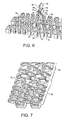
- FIGS. 6 and 7 Yet another version of an attachment member is shown in FIGS. 6 and 7 .
- the attachment member 70 is a lane divider.
- the attachment member has a body with an outer surface 72 and an opposite base surface 73.
- An interactive element in the form of an upstanding plate 74 extends from the outer surface of the body.
- First and second legs 46, 47 extend from the base surface. Feet 50 project outward from the legs. The legs slip directly into the gaps 48 between adjacent hinge elements with the base surface supported on the conveying surface 36 of the belt.
- the first and second legs fit into adjacent gaps separated by a hinge element 26'.
- the first leg 46 contacts the first side 36 of the hinge element, and the second leg 47 contacts the second side of the same hinge element.
- a hinge rod inserted into the lateral passageway at the hinge joint 32 between the base surface and the feet 50 straddling the hinge element retains the attachment member firmly in position.
- these legs have a flat wall 76 that does not contact the hinge element and an opposite contoured wall 77 that matches the shape of and contacts the side of the hinge element.
- a series of sideguards or lane dividers 70 along the length of the belt can divide the belt into longitudinal lanes, such as an edge lane 78 at each edge and one or more interior lanes 79.
- the edge lanes can serve as product-free belt regions, while multiple interior lanes can separate product laterally into individual flows.
- the attachment member could include an interaction element consisting of a lateral plate to form a flight.
- a variety of surfaces could be attached to a bas surface as on the body of FIG. 2 .
- Rollers and other elements could be attached in an assembly to a belt using the attachment scheme shown. So, as these few examples suggest, the scope of the claims is not meant to be limited to the preferred exemplary versions described.
Landscapes
- Engineering & Computer Science (AREA)
- Mechanical Engineering (AREA)
- Belt Conveyors (AREA)
- Chain Conveyers (AREA)
Claims (18)
- Ein modulares Förderband (10) umfassend eine Folge von Reihen (12) aus Bandfertigbauteilen (14), wobei jede Reihe einen sich von einem ersten Ende längs zu einem zweiten Ende und seitlich von einem ersten Rand zu einem zweiten Rand (18) erstreckenden Mittelteil (24) umfasst, einen ersten Satz seitlich mit Zwischenraum angeordneter Scharnierelemente (26), die sich längs nach außen am ersten Ende des Mittelteils erstrecken, um zwischen aufeinanderfolgenden Scharnierelementen Lücken (48) zu bilden, einen zweiten Satz seitlich mit Zwischenraum angeordneter Scharnierelemente (27), die sich längs nach außen am zweiten Ende des Mittelteils erstrecken, um zwischen aufeinanderfolgenden Scharnierelementen Lücken (48) zu bilden, wobei die Scharnierelemente der ersten und zweiten Sätze jeweils eine erste Seite (56) in Richtung des ersten Rands der Reihe und eine gegenüberliegende zweite Seite (57) in Richtung des zweiten Rands und eine sich seitlich von der ersten Seite zur zweiten Seite erstreckende Öffnung (30, 31) und eine Vielzahl von Scharnierstäben (20) aufweisen, wobei die Folge von Reihen durch Verschachteln des ersten Satzes Scharnierelemente einer Reihe mit dem zweiten Satz Scharnierelemente einer angrenzenden Reihe durchgehend verbunden ist, so dass die Öffnungen verschachtelter Scharnierelemente derart ausgerichtet sind, dass sie einen seitlichen Durchgang bilden, um einen Scharnierstab aufzunehmen, um aneinandergrenzende Reihen zu einem Förderband zu verbinden, mit einer Förderfläche (36) und einer gegenüberliegenden Fläche (37), einem Befestigungselement (34; 60; 70) inklusive eines Körpers (38) mit einer Außenfläche (40; 62; 72) und einer Grundfläche (41; 63; 73), einem mit der Außenfläche verbundenen Wechselwirkungselement (42; 64; 74), einem ersten Schenkel (46) und einem sich von der Grundfläche erstreckenden zweiten Schenkel (47) zu verbinden, wobei der erste Schenkel und der zweite Schenkel jeweils einen Fuß (50) an einem fernen Ende aufweisen,
dadurch gekennzeichnet,
dass das Befestigungselement derart in dem Förderband eingebaut ist, dass die Grundfläche entweder die Förderfläche oder die gegenüberliegende Fläche berührt, und die ersten und zweiten Schenkel sich direkt von der Förderfläche oder der Außenfläche in eine oder mehrere Lücken zwischen Scharnierelementen des ersten Satzes hinein erstrecken; und
dass die ersten und zweiten Schenkel derart beabstandet sind, dass der erste Schenkel die erste Seite eines der Scharnierelemente des ersten Satzes berührt, während der zweite Schenkel die zweite Seite eines der Scharnierelemente des ersten Satzes berührt; und
die Füße durch die Scharnierstange fixiert werden, die sich durch den ersten Satz der Scharnierelemente erstreckt. - Modulares Förderband nach Anspruch 1, dadurch gekennzeichnet,
dass der erste Schenkel die erste Seite eines Scharnierelements berührt und der zweite Schenkel die zweite Seite des Scharnierelements berührt. - Modulares Förderband nach Anspruch 1,
dadurch gekennzeichnet,
dass der erste Schenkel die erste Seite eines Scharnierelements berührt und der zweite Schenkel die zweite Seite eines anderen Scharnierelements berührt. - Modulares Förderband nach Anspruch 1,
dadurch gekennzeichnet,
dass sich die ersten und zweiten Schenkel in dieselbe Lücke zwischen aufeinanderfolgenden Scharnierelementen hinein erstrecken. - Modulares Förderband nach Anspruch 1,
dadurch gekennzeichnet,
dass das Befestigungselement eine Vielzahl von Paaren erster und zweiter Schenkel beinhaltet. - Modulares Förderband nach Anspruch 1,
dadurch gekennzeichnet,
dass die Scharnierstange zwischen den Füßen des fixierten Befestigungselements und der Grundfläche des Befestigungselements angeordnet ist. - Modulares Förderband nach Anspruch 1,
dadurch gekennzeichnet,
dass die Scharnierelemente einen schmalen Ansatz (52) beinhalten, der sich längs vom Mittelteil zu einem breiteren entfernten Kopf (54) hin erstreckt, und dass die ersten und zweiten Schenkel dem Ansatz in dessen Längserstreckung allgemein entsprechen. - Modulares Förderband nach Anspruch 1,
dadurch gekennzeichnet,
dass das Wechselwirkungselement ausgewählt wird aus einer Gruppe bestehend aus einem Niederhalterflügel, einem Streifenteiler, einer Schnecke und einem Hochreibungselement. - Modulares Förderband nach Anspruch 1,
dadurch gekennzeichnet,
dass das Wechselwirkungselement einen Flügel mit einer seitlichen Spannweite umfasst und einen Stab, der den Flügel mit der Außenfläche des Befestigungselements verbindet. - Modulares Förderband nach Anspruch 1,
dadurch gekennzeichnet,
dass das Wechselwirkungselement eine Hochreibungselastomerfläche umfasst, die an der Außenfläche des Befestigungselements befestigt ist. - Modulares Förderband nach Anspruch 1,
dadurch gekennzeichnet,
dass das Befestigungselement des Weiteren einen Träger (44) beinhaltet, der sich seitlich entlang der Außenfläche des Befestigungselements erstreckt. - Modulares Förderband nach Anspruch 11,
dadurch gekennzeichnet,
dass der Träger einen T-förmigen Querschnitt aufweist und dass das Wechselwirkungselement eine Hochreibungselastomerfläche umfasst, die an der Außenfläche und dem T-förmigen Träger des Befestigungselements befestigt ist. - Modulares Förderband nach Anspruch 1,
dadurch gekennzeichnet,
dass das Wechselwirkungselement eine Platte (74) umfasst, die sich auswärts von der Grundfläche zum Befestigungselement erstreckt. - Befestigungselement (34) zur Montage in einem modularen Plastikförderband, wobei das Befestigungselement einen Körper (38) mit einer Außenfläche (40) und einer Grundfläche (41) umfasst, ein mit der Außenfläche verbundenes Wechselwirkungselement (42) und eine Vielzahl von seitlich beabstandeten Schenkeln (46, 47), die sich von der Grundfläche erstrecken,
dadurch gekennzeichnet,
dass der Seitenabstand zwischen seitlich aufeinanderfolgenden Schenkeln zwischen einem ersten breiten Abstand und einem zweiten engen Abstand variiert. - Befestigungselement nach Anspruch 14,
dadurch gekennzeichnet,
dass jeder der Schenkel einen Fuß beinhaltet, der sich auswärts von einem fernen Ende des Schenkels erstreckt. - Befestigungselement nach Anspruch 14,
dadurch gekennzeichnet,
dass das Wechselwirkungselement einen Flügel umfasst, der eine seitliche Spannweite und einen den Flügel mit der Außenfläche des Befestigungselements verbindenden Träger aufweist. - Befestigungselement nach Anspruch 14,
dadurch gekennzeichnet,
dass das Wechselwirkungselement eine Hochreibungselastomerfläche umfasst, die an der Außenfläche des Befestigungselements befestigt ist. - Befestigungselement nach Anspruch 14,
dadurch gekennzeichnet,
dass das Befestigungselement des Weiteren einen Träger beinhaltet, der sich seitlich entlang der Außenfläche des Befestigungselements erstreckt.
Applications Claiming Priority (2)
| Application Number | Priority Date | Filing Date | Title |
|---|---|---|---|
| US11/160,049 US7494006B2 (en) | 2005-06-07 | 2005-06-07 | Modular conveyor belts and attachments |
| PCT/US2006/021377 WO2006132942A1 (en) | 2005-06-07 | 2006-06-02 | Modular conveyor belts and attachments |
Publications (2)
| Publication Number | Publication Date |
|---|---|
| EP1890951A1 EP1890951A1 (de) | 2008-02-27 |
| EP1890951B1 true EP1890951B1 (de) | 2009-07-22 |
Family
ID=37022991
Family Applications (1)
| Application Number | Title | Priority Date | Filing Date |
|---|---|---|---|
| EP06771901A Active EP1890951B1 (de) | 2005-06-07 | 2006-06-02 | Modulare förderbänder und befestigungen |
Country Status (9)
| Country | Link |
|---|---|
| US (1) | US7494006B2 (de) |
| EP (1) | EP1890951B1 (de) |
| JP (1) | JP5085537B2 (de) |
| CN (1) | CN101218158B (de) |
| AU (1) | AU2006255571B2 (de) |
| CA (1) | CA2610823C (de) |
| DE (1) | DE602006007996D1 (de) |
| DK (1) | DK1890951T3 (de) |
| WO (1) | WO2006132942A1 (de) |
Cited By (1)
| Publication number | Priority date | Publication date | Assignee | Title |
|---|---|---|---|---|
| WO2017023488A1 (en) * | 2015-08-05 | 2017-02-09 | Laitram, L.L.C. | Conveyor belt and modules with flights at the hinge |
Families Citing this family (32)
| Publication number | Priority date | Publication date | Assignee | Title |
|---|---|---|---|---|
| DE102004021262A1 (de) * | 2004-04-30 | 2005-11-17 | Sander Hansen A/S | Pasteur mit Förderband |
| JP2008265933A (ja) | 2007-04-18 | 2008-11-06 | Tsubakimoto Chain Co | 作業路用コンベヤチェーン |
| ITMI20080345A1 (it) * | 2008-02-29 | 2009-09-01 | Regina Catene Calibrate Spa | "tappeto trasportatore con mezzi di guida per percorsi curvilinei e moduli per esso" |
| US7891481B2 (en) * | 2008-09-11 | 2011-02-22 | Laitram, L.L.C. | Conveyor belt for mounting oblique rollers on lateral rods |
| WO2010081061A1 (en) * | 2009-01-12 | 2010-07-15 | Laitram, L.L.C. | Metal-fused plastic conveyor belt components and methods of making |
| IES20090591A2 (en) | 2009-07-30 | 2010-10-27 | Iaws Technology & Global Services Ltd | A conveyor |
| IT1396487B1 (it) * | 2009-12-04 | 2012-12-14 | Bett Sistemi Srl | Convogliatore. |
| DK201000294A (en) | 2010-04-08 | 2011-10-09 | Ammeraal Beltech Modular As | Restrictor clip |
| US8574044B2 (en) | 2010-08-11 | 2013-11-05 | Industrial Design Fabrication & Installation, Inc. | Belly hook assembly for a conveyor |
| US8074791B1 (en) | 2010-08-11 | 2011-12-13 | Industrial Design Fabrication & Installation, Inc. | Hook assembly for a conveyor belt |
| DK2729389T3 (en) * | 2011-07-06 | 2015-08-10 | Ammeraal Beltech Modular As | modular belt links |
| DE102011114250A1 (de) * | 2011-09-23 | 2013-03-28 | Iwis Antriebssysteme Gmbh & Co. Kg | Förderkette |
| KR101773738B1 (ko) * | 2011-12-06 | 2017-08-31 | 애슈워쓰 브라더스, 인코포레이티드 | 정렬 형상부를 갖는 컨베이어 벨트 |
| US8752698B2 (en) | 2011-12-06 | 2014-06-17 | Ashworth Bros., Inc. | Conveyor belt with alignment features |
| US8863944B2 (en) * | 2012-02-20 | 2014-10-21 | Laitram, L.L.C. | Abrasion resistant conveyor belt |
| MX2015004619A (es) | 2012-10-25 | 2016-01-12 | Solus Ind Innovations Llc | Dispositivos y metodos de indicación de desgaste del sistema de banda transportadora. |
| US9751694B2 (en) | 2012-11-29 | 2017-09-05 | Solus Industrial Innovations, Llc | Side-flexing conveyors |
| EP3015405B1 (de) * | 2013-06-28 | 2021-09-01 | Tsubakimoto Chain Co. | Förderband und kettenglied |
| ES2697755T3 (es) * | 2013-09-30 | 2019-01-28 | Laitram Llc | Módulo de cinta transportadora magnética |
| US9248970B2 (en) * | 2014-04-09 | 2016-02-02 | Natel Energy, Inc. | Belt attachment and system |
| AU2016201952B2 (en) * | 2015-03-31 | 2021-03-04 | Joy Global Underground Mining Llc | Mobile sizer with reduced fines generation |
| US10099859B2 (en) | 2015-04-15 | 2018-10-16 | Laitram, L.L.C. | Self-stacking spiral modular plastic conveyor belt with intermediate support |
| US10155625B1 (en) * | 2015-09-01 | 2018-12-18 | Laitram, L.L.C. | Conveyor belts and modules with twist-lock accessories |
| EP3269675B1 (de) * | 2016-07-15 | 2020-11-18 | Otis Elevator Company | Transportelement für einen personenbeförderer |
| US10065802B1 (en) * | 2017-04-17 | 2018-09-04 | Laitram, L.L.C. | Modular conveyor belt integrating a high density array of rollers |
| ES3037544T3 (en) * | 2017-07-19 | 2025-10-02 | Laitram Llc | Modular conveyor belt integrating lane dividers |
| CN110697321B (zh) * | 2019-09-27 | 2025-03-11 | 华南新海(深圳)科技股份有限公司 | 一种便于拆装的组合模块传输带 |
| BR112022013142A2 (pt) | 2020-01-06 | 2022-09-06 | Laitram Llc | Montagem de acesso exclusivo para uma correia transportadora |
| EP4225675A1 (de) * | 2020-10-09 | 2023-08-16 | Marel Poultry B.V. | Förderbandmodul mit abschnitten zum überlappen |
| KR20230131819A (ko) * | 2020-10-09 | 2023-09-14 | 마렐 폴트리 비.브이. | 컨베이어 벨트 모듈용 부착 유닛 |
| US12486114B2 (en) * | 2021-03-23 | 2025-12-02 | Laitram, L.L.C. | Conveyor belt module including edge protrusion |
| BE1031591B1 (nl) | 2023-05-08 | 2024-12-11 | Marelec Food Tech | Modulaire schakelband voor positioneermachines |
Family Cites Families (25)
| Publication number | Priority date | Publication date | Assignee | Title |
|---|---|---|---|---|
| US2796972A (en) * | 1955-05-10 | 1957-06-25 | Link Belt Co | Attachment link for conveyor chains |
| US4084687A (en) * | 1976-07-02 | 1978-04-18 | The Laitram Corporation | Conveyor having resilient conveying surface |
| US4556142A (en) | 1983-01-12 | 1985-12-03 | The Laitram Corporation | Lightweight modular conveyor belt |
| US4640410A (en) | 1983-10-11 | 1987-02-03 | Palmaer K V | Conveying system of the type in which plastic carriers are mounted on plastic links of a conveyor chain |
| US4832183A (en) | 1984-08-20 | 1989-05-23 | The Laitram Corporation | Conveyor belt having insertable & selectable conveying member |
| US4925013A (en) | 1984-08-20 | 1990-05-15 | The Laitram Corporation | Conveyor belt having a high friction conveying surface |
| US4972942A (en) | 1988-07-18 | 1990-11-27 | Faulkner William G | Conveyor belt |
| SE9004102D0 (sv) | 1990-12-21 | 1990-12-21 | Skf Specialty Product Ab | Plastkedja och monterbar laasningslaepp respektive styrtapp |
| IT1250684B (it) | 1991-07-19 | 1995-04-21 | Regina Sud Spa | Metodo realizzativo e trasportatore a catena con elementi di coperturain materiale cedevole. |
| US5280833A (en) | 1991-08-27 | 1994-01-25 | Andre Robin | Turn conveyor with reduced friction feature |
| US5165514A (en) * | 1992-02-06 | 1992-11-24 | Faulkner William G | Conveyor flight assembly |
| US5361893A (en) | 1993-11-18 | 1994-11-08 | The Laitram Corporation | High friction plastic conveyor belts having modular links formed by two integrated plastic materials |
| DE69510423T2 (de) | 1994-04-15 | 2000-02-24 | Jorgen Draebel | Förderkette mit einer tragfläche aufgebaut aus kettengliedern quer zur längsrichtung dieser förderkette |
| US5497874A (en) * | 1994-06-20 | 1996-03-12 | Span Tech Corporation | Article engaging insert for modular link conveyor |
| US5469956A (en) | 1995-01-20 | 1995-11-28 | The Laitram Corporation | Modular conveyor belt and flight members therefor |
| US5573105A (en) | 1995-11-08 | 1996-11-12 | Palmaer; Karl V. | Radius conveyor with guide rollers |
| US6073756A (en) | 1998-01-23 | 2000-06-13 | Uni-Chains A/S | Side-flexing conveyor belt |
| US6318544B1 (en) | 1999-11-05 | 2001-11-20 | The Laitram Corporation | Changing the characteristics of an article-conveying belt surface on a running conveyor |
| DK200000460A (da) * | 2000-03-20 | 2001-09-21 | Uni Chains As | Modulenhed til frembringelse af transportør |
| US6364095B1 (en) | 2000-04-13 | 2002-04-02 | Span Tech Llc | Modular conveyor system with side flexing belt having roller support |
| US6382404B1 (en) * | 2000-12-21 | 2002-05-07 | Habasit Ag | Corrugated flight module |
| US6554129B2 (en) | 2001-03-08 | 2003-04-29 | The Laitram Corporation | Attachments in modular conveyor belts |
| US6467610B1 (en) | 2001-10-02 | 2002-10-22 | The Laitram Corporation | Modular conveyor belts with pin-retained attachments |
| US6926134B2 (en) * | 2003-06-02 | 2005-08-09 | Laitram, L.L.C. | Plastic conveyor belt module with embedded fasteners |
| US6837367B1 (en) | 2003-11-05 | 2005-01-04 | Laitram, L.L.C. | Modular plastic conveyor belt with high beam strength |
-
2005
- 2005-06-07 US US11/160,049 patent/US7494006B2/en not_active Expired - Lifetime
-
2006
- 2006-06-02 JP JP2008515782A patent/JP5085537B2/ja active Active
- 2006-06-02 CA CA2610823A patent/CA2610823C/en active Active
- 2006-06-02 DE DE602006007996T patent/DE602006007996D1/de active Active
- 2006-06-02 EP EP06771901A patent/EP1890951B1/de active Active
- 2006-06-02 AU AU2006255571A patent/AU2006255571B2/en active Active
- 2006-06-02 DK DK06771901T patent/DK1890951T3/da active
- 2006-06-02 WO PCT/US2006/021377 patent/WO2006132942A1/en not_active Ceased
- 2006-06-02 CN CN2006800247436A patent/CN101218158B/zh active Active
Cited By (1)
| Publication number | Priority date | Publication date | Assignee | Title |
|---|---|---|---|---|
| WO2017023488A1 (en) * | 2015-08-05 | 2017-02-09 | Laitram, L.L.C. | Conveyor belt and modules with flights at the hinge |
Also Published As
| Publication number | Publication date |
|---|---|
| US20060272931A1 (en) | 2006-12-07 |
| JP5085537B2 (ja) | 2012-11-28 |
| CA2610823C (en) | 2014-04-22 |
| AU2006255571B2 (en) | 2011-08-04 |
| DE602006007996D1 (de) | 2009-09-03 |
| JP2008542158A (ja) | 2008-11-27 |
| WO2006132942A1 (en) | 2006-12-14 |
| DK1890951T3 (da) | 2009-09-28 |
| CA2610823A1 (en) | 2006-12-14 |
| EP1890951A1 (de) | 2008-02-27 |
| CN101218158A (zh) | 2008-07-09 |
| US7494006B2 (en) | 2009-02-24 |
| AU2006255571A1 (en) | 2006-12-14 |
| CN101218158B (zh) | 2012-06-27 |
Similar Documents
| Publication | Publication Date | Title |
|---|---|---|
| EP1890951B1 (de) | Modulare förderbänder und befestigungen | |
| US6467610B1 (en) | Modular conveyor belts with pin-retained attachments | |
| EP1585692B1 (de) | Flexibles mitnehmermodul für modulare kunststoff-förderbänder | |
| EP2091848B1 (de) | Modulares Förderband mit spaltlosem Seitenschutz | |
| US6644466B2 (en) | Platform-top radius belt and modules | |
| CN106794940B (zh) | 具有倾斜传动表面的输送带模块 | |
| US20020125108A1 (en) | Attachments in modular conveyor belts | |
| EP1479623B1 (de) | modulares trogförmiges Förderband | |
| US8371436B2 (en) | Conveyor provided with side guard, and side guard element | |
| CN104428221B (zh) | 可清洁的输送带和输送路径 | |
| US12145804B2 (en) | Conveyor belt module with wear pads | |
| US8905228B2 (en) | Self-supporting conveyor belt | |
| US9540177B1 (en) | Conveyor belt and modules with flights at the hinge | |
| US7267222B2 (en) | Low cost flight attachment for modular belts | |
| NL2004116C2 (en) | Modular conveyor belt. |
Legal Events
| Date | Code | Title | Description |
|---|---|---|---|
| PUAI | Public reference made under article 153(3) epc to a published international application that has entered the european phase |
Free format text: ORIGINAL CODE: 0009012 |
|
| 17P | Request for examination filed |
Effective date: 20071213 |
|
| AK | Designated contracting states |
Kind code of ref document: A1 Designated state(s): AT BE BG CH CY CZ DE DK EE ES FI FR GB GR HU IE IS IT LI LT LU LV MC NL PL PT RO SE SI SK TR |
|
| 17Q | First examination report despatched |
Effective date: 20080227 |
|
| RIN1 | Information on inventor provided before grant (corrected) |
Inventor name: DAILEY, R. SCOTT Inventor name: KNOTT, ERROL P. Inventor name: MACLACHLAN, GILBERT J. Inventor name: KLEIN, RICHARD M. |
|
| DAX | Request for extension of the european patent (deleted) | ||
| GRAP | Despatch of communication of intention to grant a patent |
Free format text: ORIGINAL CODE: EPIDOSNIGR1 |
|
| GRAS | Grant fee paid |
Free format text: ORIGINAL CODE: EPIDOSNIGR3 |
|
| GRAA | (expected) grant |
Free format text: ORIGINAL CODE: 0009210 |
|
| AK | Designated contracting states |
Kind code of ref document: B1 Designated state(s): AT BE BG CH CY CZ DE DK EE ES FI FR GB GR HU IE IS IT LI LT LU LV MC NL PL PT RO SE SI SK TR |
|
| REG | Reference to a national code |
Ref country code: GB Ref legal event code: FG4D |
|
| REG | Reference to a national code |
Ref country code: CH Ref legal event code: NV Representative=s name: HANS RUDOLF GACHNANG PATENTANWALT Ref country code: CH Ref legal event code: EP |
|
| REG | Reference to a national code |
Ref country code: IE Ref legal event code: FG4D |
|
| REF | Corresponds to: |
Ref document number: 602006007996 Country of ref document: DE Date of ref document: 20090903 Kind code of ref document: P |
|
| REG | Reference to a national code |
Ref country code: DE Ref legal event code: R096 Ref document number: 602006007996 Country of ref document: DE Effective date: 20090903 |
|
| REG | Reference to a national code |
Ref country code: DK Ref legal event code: T3 |
|
| PG25 | Lapsed in a contracting state [announced via postgrant information from national office to epo] |
Ref country code: IS Free format text: LAPSE BECAUSE OF FAILURE TO SUBMIT A TRANSLATION OF THE DESCRIPTION OR TO PAY THE FEE WITHIN THE PRESCRIBED TIME-LIMIT Effective date: 20091122 Ref country code: SE Free format text: LAPSE BECAUSE OF FAILURE TO SUBMIT A TRANSLATION OF THE DESCRIPTION OR TO PAY THE FEE WITHIN THE PRESCRIBED TIME-LIMIT Effective date: 20090722 Ref country code: LT Free format text: LAPSE BECAUSE OF FAILURE TO SUBMIT A TRANSLATION OF THE DESCRIPTION OR TO PAY THE FEE WITHIN THE PRESCRIBED TIME-LIMIT Effective date: 20090722 Ref country code: FI Free format text: LAPSE BECAUSE OF FAILURE TO SUBMIT A TRANSLATION OF THE DESCRIPTION OR TO PAY THE FEE WITHIN THE PRESCRIBED TIME-LIMIT Effective date: 20090722 Ref country code: ES Free format text: LAPSE BECAUSE OF FAILURE TO SUBMIT A TRANSLATION OF THE DESCRIPTION OR TO PAY THE FEE WITHIN THE PRESCRIBED TIME-LIMIT Effective date: 20091102 Ref country code: AT Free format text: LAPSE BECAUSE OF FAILURE TO SUBMIT A TRANSLATION OF THE DESCRIPTION OR TO PAY THE FEE WITHIN THE PRESCRIBED TIME-LIMIT Effective date: 20090722 |
|
| PG25 | Lapsed in a contracting state [announced via postgrant information from national office to epo] |
Ref country code: LV Free format text: LAPSE BECAUSE OF FAILURE TO SUBMIT A TRANSLATION OF THE DESCRIPTION OR TO PAY THE FEE WITHIN THE PRESCRIBED TIME-LIMIT Effective date: 20090722 Ref country code: SI Free format text: LAPSE BECAUSE OF FAILURE TO SUBMIT A TRANSLATION OF THE DESCRIPTION OR TO PAY THE FEE WITHIN THE PRESCRIBED TIME-LIMIT Effective date: 20090722 Ref country code: PL Free format text: LAPSE BECAUSE OF FAILURE TO SUBMIT A TRANSLATION OF THE DESCRIPTION OR TO PAY THE FEE WITHIN THE PRESCRIBED TIME-LIMIT Effective date: 20090722 |
|
| PG25 | Lapsed in a contracting state [announced via postgrant information from national office to epo] |
Ref country code: PT Free format text: LAPSE BECAUSE OF FAILURE TO SUBMIT A TRANSLATION OF THE DESCRIPTION OR TO PAY THE FEE WITHIN THE PRESCRIBED TIME-LIMIT Effective date: 20091122 Ref country code: BG Free format text: LAPSE BECAUSE OF FAILURE TO SUBMIT A TRANSLATION OF THE DESCRIPTION OR TO PAY THE FEE WITHIN THE PRESCRIBED TIME-LIMIT Effective date: 20091022 |
|
| PG25 | Lapsed in a contracting state [announced via postgrant information from national office to epo] |
Ref country code: CZ Free format text: LAPSE BECAUSE OF FAILURE TO SUBMIT A TRANSLATION OF THE DESCRIPTION OR TO PAY THE FEE WITHIN THE PRESCRIBED TIME-LIMIT Effective date: 20090722 Ref country code: EE Free format text: LAPSE BECAUSE OF FAILURE TO SUBMIT A TRANSLATION OF THE DESCRIPTION OR TO PAY THE FEE WITHIN THE PRESCRIBED TIME-LIMIT Effective date: 20090722 Ref country code: RO Free format text: LAPSE BECAUSE OF FAILURE TO SUBMIT A TRANSLATION OF THE DESCRIPTION OR TO PAY THE FEE WITHIN THE PRESCRIBED TIME-LIMIT Effective date: 20090722 |
|
| PLBE | No opposition filed within time limit |
Free format text: ORIGINAL CODE: 0009261 |
|
| PG25 | Lapsed in a contracting state [announced via postgrant information from national office to epo] |
Ref country code: SK Free format text: LAPSE BECAUSE OF FAILURE TO SUBMIT A TRANSLATION OF THE DESCRIPTION OR TO PAY THE FEE WITHIN THE PRESCRIBED TIME-LIMIT Effective date: 20090722 Ref country code: BE Free format text: LAPSE BECAUSE OF FAILURE TO SUBMIT A TRANSLATION OF THE DESCRIPTION OR TO PAY THE FEE WITHIN THE PRESCRIBED TIME-LIMIT Effective date: 20090722 |
|
| 26N | No opposition filed |
Effective date: 20100423 |
|
| REG | Reference to a national code |
Ref country code: DE Ref legal event code: R097 Ref document number: 602006007996 Country of ref document: DE Effective date: 20100423 |
|
| PG25 | Lapsed in a contracting state [announced via postgrant information from national office to epo] |
Ref country code: GR Free format text: LAPSE BECAUSE OF FAILURE TO SUBMIT A TRANSLATION OF THE DESCRIPTION OR TO PAY THE FEE WITHIN THE PRESCRIBED TIME-LIMIT Effective date: 20091023 |
|
| PG25 | Lapsed in a contracting state [announced via postgrant information from national office to epo] |
Ref country code: MC Free format text: LAPSE BECAUSE OF NON-PAYMENT OF DUE FEES Effective date: 20100630 |
|
| PG25 | Lapsed in a contracting state [announced via postgrant information from national office to epo] |
Ref country code: IE Free format text: LAPSE BECAUSE OF NON-PAYMENT OF DUE FEES Effective date: 20100602 |
|
| PG25 | Lapsed in a contracting state [announced via postgrant information from national office to epo] |
Ref country code: CY Free format text: LAPSE BECAUSE OF FAILURE TO SUBMIT A TRANSLATION OF THE DESCRIPTION OR TO PAY THE FEE WITHIN THE PRESCRIBED TIME-LIMIT Effective date: 20090722 |
|
| PG25 | Lapsed in a contracting state [announced via postgrant information from national office to epo] |
Ref country code: LU Free format text: LAPSE BECAUSE OF NON-PAYMENT OF DUE FEES Effective date: 20100602 Ref country code: HU Free format text: LAPSE BECAUSE OF FAILURE TO SUBMIT A TRANSLATION OF THE DESCRIPTION OR TO PAY THE FEE WITHIN THE PRESCRIBED TIME-LIMIT Effective date: 20100123 |
|
| PG25 | Lapsed in a contracting state [announced via postgrant information from national office to epo] |
Ref country code: TR Free format text: LAPSE BECAUSE OF FAILURE TO SUBMIT A TRANSLATION OF THE DESCRIPTION OR TO PAY THE FEE WITHIN THE PRESCRIBED TIME-LIMIT Effective date: 20090722 |
|
| REG | Reference to a national code |
Ref country code: CH Ref legal event code: NV Representative=s name: GACHNANG AG PATENTANWAELTE, CH |
|
| REG | Reference to a national code |
Ref country code: FR Ref legal event code: PLFP Year of fee payment: 11 |
|
| REG | Reference to a national code |
Ref country code: FR Ref legal event code: PLFP Year of fee payment: 12 |
|
| REG | Reference to a national code |
Ref country code: FR Ref legal event code: PLFP Year of fee payment: 13 |
|
| P01 | Opt-out of the competence of the unified patent court (upc) registered |
Effective date: 20230613 |
|
| REG | Reference to a national code |
Ref country code: CH Ref legal event code: PK Free format text: BERICHTIGUNGEN |
|
| PGFP | Annual fee paid to national office [announced via postgrant information from national office to epo] |
Ref country code: NL Payment date: 20250515 Year of fee payment: 20 |
|
| PGFP | Annual fee paid to national office [announced via postgrant information from national office to epo] |
Ref country code: DE Payment date: 20250509 Year of fee payment: 20 |
|
| PGFP | Annual fee paid to national office [announced via postgrant information from national office to epo] |
Ref country code: GB Payment date: 20250508 Year of fee payment: 20 Ref country code: DK Payment date: 20250527 Year of fee payment: 20 |
|
| PGFP | Annual fee paid to national office [announced via postgrant information from national office to epo] |
Ref country code: FR Payment date: 20250512 Year of fee payment: 20 |
|
| PGFP | Annual fee paid to national office [announced via postgrant information from national office to epo] |
Ref country code: IT Payment date: 20250610 Year of fee payment: 20 |
|
| PGFP | Annual fee paid to national office [announced via postgrant information from national office to epo] |
Ref country code: CH Payment date: 20250701 Year of fee payment: 20 |