EP1891704B1 - Parafoudre multipole et/ou protecteur contre les surtensions de foudre dans ume realisation de barrette de bornes - Google Patents
Parafoudre multipole et/ou protecteur contre les surtensions de foudre dans ume realisation de barrette de bornes Download PDFInfo
- Publication number
- EP1891704B1 EP1891704B1 EP07717681A EP07717681A EP1891704B1 EP 1891704 B1 EP1891704 B1 EP 1891704B1 EP 07717681 A EP07717681 A EP 07717681A EP 07717681 A EP07717681 A EP 07717681A EP 1891704 B1 EP1891704 B1 EP 1891704B1
- Authority
- EP
- European Patent Office
- Prior art keywords
- printed circuit
- contact
- base part
- surge arrester
- module
- Prior art date
- Legal status (The legal status is an assumption and is not a legal conclusion. Google has not performed a legal analysis and makes no representation as to the accuracy of the status listed.)
- Not-in-force
Links
- 230000001681 protective effect Effects 0.000 claims abstract description 17
- 238000005516 engineering process Methods 0.000 claims abstract description 8
- 210000002105 tongue Anatomy 0.000 claims description 27
- PXHVJJICTQNCMI-UHFFFAOYSA-N Nickel Chemical compound [Ni] PXHVJJICTQNCMI-UHFFFAOYSA-N 0.000 claims description 6
- 230000000295 complement effect Effects 0.000 claims description 6
- 238000009413 insulation Methods 0.000 claims description 3
- 238000012544 monitoring process Methods 0.000 claims description 3
- 229910052759 nickel Inorganic materials 0.000 claims description 3
- 239000000758 substrate Substances 0.000 claims 1
- 230000015572 biosynthetic process Effects 0.000 description 5
- 230000005405 multipole Effects 0.000 description 5
- 238000013461 design Methods 0.000 description 3
- 238000010586 diagram Methods 0.000 description 3
- XEEYBQQBJWHFJM-UHFFFAOYSA-N Iron Chemical compound [Fe] XEEYBQQBJWHFJM-UHFFFAOYSA-N 0.000 description 2
- 239000004020 conductor Substances 0.000 description 2
- 239000007787 solid Substances 0.000 description 2
- RYGMFSIKBFXOCR-UHFFFAOYSA-N Copper Chemical compound [Cu] RYGMFSIKBFXOCR-UHFFFAOYSA-N 0.000 description 1
- 241000233805 Phoenix Species 0.000 description 1
- ATJFFYVFTNAWJD-UHFFFAOYSA-N Tin Chemical compound [Sn] ATJFFYVFTNAWJD-UHFFFAOYSA-N 0.000 description 1
- 239000011248 coating agent Substances 0.000 description 1
- 238000000576 coating method Methods 0.000 description 1
- 238000004891 communication Methods 0.000 description 1
- 238000010276 construction Methods 0.000 description 1
- 229910052802 copper Inorganic materials 0.000 description 1
- 239000010949 copper Substances 0.000 description 1
- 230000001419 dependent effect Effects 0.000 description 1
- 238000011161 development Methods 0.000 description 1
- 230000018109 developmental process Effects 0.000 description 1
- 238000006073 displacement reaction Methods 0.000 description 1
- 230000000694 effects Effects 0.000 description 1
- 238000005530 etching Methods 0.000 description 1
- 230000002349 favourable effect Effects 0.000 description 1
- 230000036039 immunity Effects 0.000 description 1
- 238000003780 insertion Methods 0.000 description 1
- 230000037431 insertion Effects 0.000 description 1
- 238000009434 installation Methods 0.000 description 1
- 229910052742 iron Inorganic materials 0.000 description 1
- 238000004519 manufacturing process Methods 0.000 description 1
- 238000002844 melting Methods 0.000 description 1
- 230000008018 melting Effects 0.000 description 1
- 230000007935 neutral effect Effects 0.000 description 1
- 238000003825 pressing Methods 0.000 description 1
- 238000003860 storage Methods 0.000 description 1
- 239000000725 suspension Substances 0.000 description 1
Images




Classifications
-
- H—ELECTRICITY
- H01—ELECTRIC ELEMENTS
- H01R—ELECTRICALLY-CONDUCTIVE CONNECTIONS; STRUCTURAL ASSOCIATIONS OF A PLURALITY OF MUTUALLY-INSULATED ELECTRICAL CONNECTING ELEMENTS; COUPLING DEVICES; CURRENT COLLECTORS
- H01R9/00—Structural associations of a plurality of mutually-insulated electrical connecting elements, e.g. terminal strips or terminal blocks; Terminals or binding posts mounted upon a base or in a case; Bases therefor
- H01R9/22—Bases, e.g. strip, block, panel
- H01R9/24—Terminal blocks
- H01R9/26—Clip-on terminal blocks for side-by-side rail- or strip-mounting
- H01R9/2625—Clip-on terminal blocks for side-by-side rail- or strip-mounting with built-in electrical component
- H01R9/2641—Clip-on terminal blocks for side-by-side rail- or strip-mounting with built-in electrical component with built-in overvoltage protection
-
- H—ELECTRICITY
- H05—ELECTRIC TECHNIQUES NOT OTHERWISE PROVIDED FOR
- H05K—PRINTED CIRCUITS; CASINGS OR CONSTRUCTIONAL DETAILS OF ELECTRIC APPARATUS; MANUFACTURE OF ASSEMBLAGES OF ELECTRICAL COMPONENTS
- H05K1/00—Printed circuits
- H05K1/02—Details
- H05K1/0213—Electrical arrangements not otherwise provided for
- H05K1/0254—High voltage adaptations; Electrical insulation details; Overvoltage or electrostatic discharge protection ; Arrangements for regulating voltages or for using plural voltages
-
- H—ELECTRICITY
- H05—ELECTRIC TECHNIQUES NOT OTHERWISE PROVIDED FOR
- H05K—PRINTED CIRCUITS; CASINGS OR CONSTRUCTIONAL DETAILS OF ELECTRIC APPARATUS; MANUFACTURE OF ASSEMBLAGES OF ELECTRICAL COMPONENTS
- H05K1/00—Printed circuits
- H05K1/02—Details
- H05K1/14—Structural association of two or more printed circuits
- H05K1/144—Stacked arrangements of planar printed circuit boards
Definitions
- the invention relates to a multi-pole Blitzstram and / or surge arrester in terminal block design for the protection of equipment and information systems, consisting of base part as Autogangsklemne, insertable in the base insert modules with protective elements and means for DIN rail mounting, wherein spring contacts are formed in the base part for each plug-in module and the plug-in module has a hood-shaped housing, which accommodates in its interior at least one printed circuit board, which carries the protective elements, according to the preamble of patent claim 1.
- protection devices of the series "Blitzductor” (registered trademark) from DEHN & S ⁇ HNE GmbH + Co. KG, Neu here, may be mentioned here.
- Blitzstran- and surge arresters which are available as standard devices in terminal block technology, two-pole, but also four-pole variants are available on the market.
- the overvoltage protection devices can be used here as lightning strambulists, kanban arresters or as surge arresters.
- the known devices enable the coordinated use in the EMC-oriented lightning protection zone concept according to VDE 0185-103 with a protection effect adapted to the EMC interference immunity for devices of the Fermelde, MSR and data technology.
- the previously known surge arresters are equipped by a two-part construction with a base part as a through terminal for receiving the protection modules and with selectable surge protection modules. Due to the small width, the result is a compact, space-saving design. A signal interruption when changing the modules does not occur and it has the base part on an integrated shield terminal.
- the shield earthing is possible directly and indirectly. The grounding is done via a support foot with snap fastening by preferred DIN rail mounting.
- overvoltage arresters from Phoenix Contact GmbH & Co. KG, for example van type MCR-PLUGTRAB, are also available in a series terminal block with multi-stage overvoltage protection, with a printed circuit board inside the arrester that carries the protective elements.
- the contacting with a base part is uninterrupted and impedance neutral, with this separate solid pin-like plug contacts are provided on the male part.
- a multi-pole lightning current and / or surge arrester according to the preamble of claim 1 is made US 4 922 374 A known.
- a support frame is first arranged in the housing of the plug-in module of the overall arrangement, wherein on the respective outer sides of the support frame each a Leiteiplatte is located, which in its final position, i. in the assembled state parallel to each other.
- a third Leiteiplatte is arranged such that by the support frame and thereby resulting spacing of the circuit boards with each other, the necessary creepage distances and air gaps between the circuit boards and the protection elements located there are realized.
- the housing encloses the resulting sandwich arrangement of the circuit boards and the support frame and fixes the items of this assembly.
- the support frame has in particular a rectangular shape and has an outer contour with recesses or shoulders as a stop for correspondingly complementary embodiments of the respective printed circuit boards. These recesses serve also as coding, in order to avoid confusion when using printed circuit boards
- the support frame has on its upper side at least one slot-shaped opening to the third printed circuit board réellebehen leader. On the mounting side, therefore, the third circuit board is secured against displacement by the slot-shaped opening.
- the carrier frame preferably has a corresponding transverse web which acts as a stop.
- each means for releasably latching connection with complementary recesses on the base part are present. These locking means prevent unwanted detachment of the plug-in module from the base part.
- the fixed from the outer sides of the support frame printed circuit boards have from the housing of the plug-in module pin-like outstanding, integrally molded portions which form contact tongues.
- the projecting portions of the outside conducting plates which form contact tongues are directed with their conductive coated side facing each other.
- the contact tongues are coated with a nickel layer.
- a printed circuit board is arranged in the region of the slot openings, oriented in each case in the plugging direction.
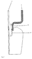
- the respective circuit board is assigned in each case at least one resilient wire hanger, wherein not plugged plug-in module, the respective wire hanger in contact with the respective conductive portion of the base part circuit board and this contact interrupted when inserting the plug-in module by the contact tongues and a connection of the contact tongues of the plug-in module the wire hanger is made.
- the thickness of the respective carrier layer of the printed circuit board contact tongue forms the insulation between the wire clip and the base part printed circuit board.
- the wire hanger have in longitudinal section on a V or U-shape with two opposite legs, wherein a leg with the contact tongue or the base part circuit board and the other leg with the respective outer terminal comes into electrical connection or is.
- the contact surfaces of the wire hanger are provided with slots. These slots can be made parallel and are pointing in the contact surface Starting leg from leg end up into the leg connection area.
- the third circuit board includes means for wireless fault and condition monitoring, e.g. in the form of an RFID transponder and, if appropriate, contains means for monitoring the temperature of the protective elements located on the remaining printed circuit boards. These means may be temperature sensors, which are respectively close, in particular opposite of the protective elements.
- a connecting spring contact iron may be provided for electrical connection between the outside printed circuit boards, a connecting spring contact iron.
- this On the top hat rail mounting base of the base part, this has an opening which releases a strap ground contact, which comes into contact with the DIN rail contact.
- the yoke ground contact has two opposing legs, the first leg being in contact with the ground terminal in the base and the second leg being in communication with the DIN rail, such that at strand flow the resulting magnetic force increases the contact pressure.
- coil spring In the bottom of the base part oriented in the insertion direction of the module spring, in particular coil spring is used, which is tensioned when inserting the module by a pin provided on the bottom thereof.
- This tensioned spring serves as a force storage device for easier removal of the module if necessary.
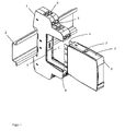
- Fig. 1 a perspective view of a base rail mounted on a DIN rail with not yet fixed in this plug-in module
- Fig. 2 an exploded view of the most essential components of the plug-in module
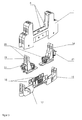
- Fig. 3 an exploded view of the most essential components of the base part
- FIG. 4 Schematic representations of the formation of the wire hanger in the base part, in the state unused plug-in module (upper part of the Fig. 4 ) and plugged module (lower part of the Fig. 4 );
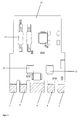
- Fig. 5 a plan view of one of the outside of the support frame located Printed circuit board with protective elements and contact tongues;
- Fig. 6 a perspective view of a wire hanger with slotted contact and a representation of the resulting force at Stramhne to increase the contact pressure
- Fig. 7 a schematic diagram of the execution of the bracket grounding contact in the base part
- Fig. 8 a schematic diagram of the embodiment of the spring contact strap for electrical connection between the two outside printed circuit boards.
- the multi-pole Blitzstram- and / or surge arrester according to the invention in terminal clamping embodiment initially comprises a base part 1, which is on a DIN rail 2 positively and non-positively fastened.
- the base part 1 receives a plug-in module 3, on the underside of contact tongues 4 are located.
- the external connection is made by conventional erklemntagenen 6 on the base part 1.
- plug-in module 3 engages a nose 7 in a corresponding recess 8 a.
- this locking connection can be solved.
- the structure of the plug-in module is based on the Fig. 2 be explained in more detail.
- the components for the overvoltage protection of a four-pole circuit are divided here into two printed circuit boards 10 (outside printed circuit boards).
- the respective associated wires are arranged on a circuit board.
- a third printed circuit board 11 is located between the two printed circuit boards 10 and in particular carries a circuit for the state control of the surge arrester, preferably with an RFID interface for non-contact status inquiry.
- a support frame 12 receives the printed circuit boards 10 and 11.
- the support frame 12 also ensures the necessary clearance and creepage distances and allows the positioning of temperature sensors (not shown) for condition control close to the components to be monitored.
- the hood-like housing 13 fixes the circuit boards 10 and 11 in conjunction with the support frame.
- Fig. 1 are on the narrow sides of the housing 13th Locking elements formed, which allow locking of the arrester module in the base part.
- the top of the support frame 12, which has a substantially rectangular shape and an outer contour with recesses or heels as a stop and confusion protection for complementary formation of the respective circuit boards may include a slot-shaped opening 14 to receive the third circuit board 11 leading.
- a transverse web 15 forms a lower stop for this third printed circuit board 11.
- the base part 1 according to Fig. 3 has an outer contour substantially similar to that of the prior art, but with the already mentioned slot openings 5, which are oriented in the connecting region between the protruding legs substantially in a line and parallel to each other.
- a bottom part 16 serves as a carrier for the ground contact 17 and for printed circuit boards 18. Furthermore, a biased by a spring locking element is integrated, which ensures the attachment to the top hat rail.
- Two inserts 19 carry wire hanger 20 for the outer terminals 21st
- the contacts of the wire hanger 20 lie against the contact surfaces of the integrated circuit boards 18 in the base part.
- the input side wire hanger 20 are connected to the output side wire hanger.
- the contact surfaces of the printed circuit board 18 in the base part are lifted by the contact tongues 4 and simultaneously connected to the contact surfaces of the contact tongues 4 of the plug-in module.
- the circuit is closed via the plug-in module with the wire hanger 20 of the base part.
- the wire hanger 20 thus fulfill the function switching and contact delivery simultaneously.
- the printed circuit boards 10 have protective elements 22 correspondingly electrically connected by the etching structure.
- the contact tongues 4 of the respective circuit board 10 turn out to be out of the Printed circuit board protruding projections.
- the contact tongues 4 are formed simultaneously with the printed circuit board 10, which carries the necessary protection elements 22 for overvoltage protection.
- the corresponding contact surface is able to carry the surge currents required for the respective arrester, which is not the case with a conventional soft tin layer with copper lying underneath.
- the contact surfaces of the wire hanger 20 are according to Fig. 6 (top picture) slotted, whereby a larger contact surface is achieved.
- the formation of the wire hanger 20 is made so that two substantially U-forming legs face each other.
- the attachment of the base part 1 on the top hat rail 2 at the same time has the task of safely guiding the leakage current of the overvoltage protection device onto the DIN rail.
- One end of the spring contact clip 25 is soldered to a printed circuit board with the free end of the spring contact clip 25 in contact with the opposite printed circuit board and a conductive surface there.
Landscapes
- Emergency Protection Circuit Devices (AREA)
- Coupling Device And Connection With Printed Circuit (AREA)
- Clamps And Clips (AREA)
- Details Of Connecting Devices For Male And Female Coupling (AREA)
Claims (18)
- Dérivateur de surtensions et/ou parafoudre multipolaire de réalisation en bomier en rangée destiné à la protection d'appareils et d'installations dans les technologies informatiques, comprenant une partie de base (1) sous forme de borne traversante, des modules enfichables (3) à mettre en place dans la partie de base (1), avec des éléments protecteurs (22) et des moyens pour le montage sur profilé-chapeau, dans lequel des contacts-ressorts pour le module enfichable respectif (3) sont réalisés dans la partie de base (1) et le module enfichable (3) comprend un boîtier (13) en forme de capot qui reçoit à l'intérieur au moins une carte à circuits imprimés (10) qui porte les éléments protecteurs (22),
caractérisé en ce que
un cadre porteur (12) et reçu dans le boîtier du module enfichable (3), de sorte qu'une carte à circuits imprimés (10) respective se trouve sur les côtés extérieurs respectifs du cadre porteur (12), entre lesquelles est agencée une troisième carte à circuits imprimés (11), tenue par le cadre porteur (12), de telle façon que les trajets de fuite et les entrefers nécessaires sont réalisés au moyen du cadre porteur (12) entre les cartes à circuits imprimés (10 ; 11) orientées parallèlement et les éléments protecteurs (22) qui s'y trouvent, et le boîtier (13) fixe en outre l'agencement en sandwich constitué des cartes à circuits imprimés (10 ; 11) et du cadre porteur (12) en les entourant. - Dérivateur de surtensions selon la revendication 1,
caractérisé en ce que le cadre porteur (12) présente une forme rectangulaire et possède un contour extérieur avec des ressauts ou des saillies à titre de butée et de protection de détrompage pour une réalisation complémentaire des cartes à circuits imprimés (10 ; 11) respectives. - Dérivateur de surtensions selon la revendication 2,
caractérisé en ce qu'il est prévu au moins une ouverture en forme de fente (14) dans le cadre porteur (12), afin de recevoir la troisième carte à circuits imprimés (11) en la guidant. - Dérivateur de surtensions selon l'une des revendications précédentes,
caractérisé en ce que des moyens respectifs destinés à la liaison détachable par enclenchement avec des évidements d'enclenchement complémentaires sur la partie de base (1) sont prévus sur les petits côtés du boîtier. - Dérivateur de surtensions selon l'une des revendications précédentes,
caractérisé en ce que les cartes à circuits imprimés (10) fixées par les côtés extérieurs du cadre porteur (12) présentent des tronçons qui sortent, à la manière de tenons, hors du boîtier (13) du module enfichable (3) et qui forment des languettes de contact (4). - Dérivateur de surtensions selon la revendication 5,
caractérisé en ce que les tronçons sortants sont orientés les uns vers les autres avec leur côté portant un revêtement conducteur. - Dérivateur de surtensions selon la revendication 5 ou 6,
caractérisé en ce que les languettes de contact (4) présentent un revêtement en nickel. - Dérivateur de surtensions selon l'une des revendications 5 à 7,
caractérisé en ce que des ouvertures en forme de fente (5) parallèles sont prévues dans la partie de base (1), lesquelles reçoivent les languettes de contact (4) ou des extrémités des languettes de contact du module enfichable (3). - Dérivateur de surtensions selon la revendication 8,
caractérisé en ce que, dans la partie de base (1) et dans la région des ouvertures en forme de fente (5), sont agencées des cartes à circuits imprimés (18) agencées respectivement dans la direction d'enfichage, auxquelles est associé au moins un arceau fourchu à effet élastique (20), de sorte que lorsque le module enfichable (3) n'est pas enfiché, les arceaux fourchus respectifs (20) sont en contact avec le tronçon conducteur respectif des cartes à circuits imprimés (10) de la partie de base et lors de la mise en place du module enfichable (3), ce contact est interrompu par les languettes de contact (4) et une connexion est établie au moyen de languettes de contact (4) avec les arceaux fourchus (20), et l'épaisseur de la couche portante respective des languettes de contact des cartes à circuits imprimés forme l'isolation entre les arceaux fourchus (20) et la carte à circuits imprimés (18) de la partie de base. - Dérivateur de surtensions selon la revendication 9,
caractérisé en ce que les étriers fourchus (20) présentent en coupe longitudinale une forme en V ou en U avec deux branches opposées, de sorte qu'une branche vient en contact électrique ou est en contact électrique avec la languette de contact (4) ou la carte à circuits imprimés (18) de la partie de base, et l'autre branche avec la borne extérieure respective. - Dérivateur de surtensions selon la revendication 9 août 10,
caractérisé en ce que les surfaces de contact des étriers fourchus (20) sont dotées de fentes, en particulier de fentes allongées. - Dérivateur de surtensions selon la revendication 11,
caractérisé en ce que les fentes sont réalisées parallèles et sont menées, dans la branche qui est tournée vers la surface de contact, en partant de l'extrémité de la branche jusque dans la zone de jonction des branches. - Dérivateur de surtensions selon l'une des revendications précédentes,
caractérisé en ce que la troisième carte à circuits imprimés (11) comprend des moyens pour la surveillance d'erreurs et d'état sans fil et/ou des capteurs de température, qui se trouvent respectivement à proximité, en particulier à l'opposé des éléments protecteurs (22), sur les cartes à circuits imprimés extérieures (10). - Dérivateur de surtensions selon l'une des revendications précédentes,
caractérisé en ce qu'il est prévu un étrier de contact à ressort (25) pour la liaison électrique entre les cartes à circuits imprimés extérieures (10). - Dérivateur de surtensions selon la revendication 14,
caractérisé en ce que la troisième carte à circuits imprimés (11) est réalisée avec une surface plus petite que les cartes à circuits imprimés extérieures (10). - Dérivateur de surtensions selon l'une des revendications précédentes,
caractérisé en ce que, au niveau de la face intérieure de fixation de la partie de base (1), destinée au rail-chapeau, la partie de base comporte une ouverture qui dégage un contact en arceau de mise à la terre (17 ; 24), qui vient en connexion avec le rail-chapeau (2). - Dérivateur de surtensions selon la revendication 16,
caractérisé en ce que le contact en arceau de mise à la terre comprend deux branches opposées, telles que la première branche vient en contact avec la borne de mise à la terre (17) dans la partie de base (1), et la seconde branche (24) est en connexion avec le rail-chapeau (2 ; 23), de sorte que lors du passage d'un courant la force magnétique résultante augmente la pression de pressage des contacts. - Dérivateur de surtensions selon l'une des revendications précédentes,
caractérisé en ce qu'un ressort, orienté dans la direction d'enfichage du module, est mis en place dans le fond de la partie de base (1) ce ressort étant bandé lors de l'enfichage du module, par une tige prévue sur ce fond, et fait office d'accumulateur de force pour faciliter l'enlèvement du module.
Priority Applications (1)
| Application Number | Priority Date | Filing Date | Title |
|---|---|---|---|
| PL07717681T PL1891704T3 (pl) | 2006-05-09 | 2007-04-03 | Wielobiegunowy odgromnik i/lub ogranicznik przepięć w wykonaniu z zaciskami szeregowymi |
Applications Claiming Priority (3)
| Application Number | Priority Date | Filing Date | Title |
|---|---|---|---|
| DE102006021607 | 2006-05-09 | ||
| DE102006034164A DE102006034164B4 (de) | 2006-05-09 | 2006-07-24 | Mehrpoliger Blitzstrom- und/oder Überspannungsableiter in Reihenklemmausführung |
| PCT/EP2007/053199 WO2007128628A1 (fr) | 2006-05-09 | 2007-04-03 | Parafoudre multipôle et/ou protecteur contre les surtensions de foudre dans une réalisation de barRette de bornes |
Publications (2)
| Publication Number | Publication Date |
|---|---|
| EP1891704A1 EP1891704A1 (fr) | 2008-02-27 |
| EP1891704B1 true EP1891704B1 (fr) | 2011-02-09 |
Family
ID=38110451
Family Applications (1)
| Application Number | Title | Priority Date | Filing Date |
|---|---|---|---|
| EP07717681A Not-in-force EP1891704B1 (fr) | 2006-05-09 | 2007-04-03 | Parafoudre multipole et/ou protecteur contre les surtensions de foudre dans ume realisation de barrette de bornes |
Country Status (8)
| Country | Link |
|---|---|
| EP (1) | EP1891704B1 (fr) |
| JP (1) | JP4997283B2 (fr) |
| CN (1) | CN101438462B (fr) |
| AT (1) | ATE498217T1 (fr) |
| DE (2) | DE102006034164B4 (fr) |
| PL (1) | PL1891704T3 (fr) |
| RU (1) | RU2394322C1 (fr) |
| WO (1) | WO2007128628A1 (fr) |
Families Citing this family (28)
| Publication number | Priority date | Publication date | Assignee | Title |
|---|---|---|---|---|
| DE102008021210B4 (de) * | 2008-01-30 | 2010-07-22 | Phoenix Contact Gmbh & Co. Kg | Überspannungsschutzgerät |
| DE102010049476A1 (de) * | 2010-10-27 | 2012-05-03 | Phoenix Contact Gmbh & Co. Kg | Elektrische Adressierungsvorrichtung |
| DE102008057748A1 (de) | 2008-11-17 | 2010-05-20 | Phoenix Contact Gmbh & Co. Kg | Elektrisches Klemmenmodul |
| DE102010012684A1 (de) * | 2010-03-24 | 2011-09-29 | Phoenix Contact Gmbh & Co. Kg | Überspannungsschutzgerät |
| US8123545B1 (en) | 2011-03-23 | 2012-02-28 | Phoenix Contact, Inc. | Latch and extractor for electronic module |
| DE102011056986A1 (de) * | 2011-12-23 | 2013-06-27 | Wago Verwaltungsgesellschaft Mbh | Leiteranschlussklemme |
| DE102013005783B4 (de) * | 2012-10-31 | 2019-06-13 | DEHN + SÖHNE GmbH + Co. KG. | Einrichtung zum betriebsspannungsunabhängigen Erzeugen eines sicheren, niederohmigen elektrischen Kurzschlusses |
| CN203225381U (zh) * | 2013-03-22 | 2013-10-02 | 欧姆龙株式会社 | 端子台和本体的连接机构、包括其的电子设备和温度调节器 |
| CN104242281B (zh) * | 2013-06-20 | 2017-04-26 | 町洋机电(中国)有限公司 | 插拔保护模块信号不间断的浪涌保护器 |
| CN104659502B (zh) * | 2013-11-19 | 2017-02-22 | 上海辰竹仪表有限公司 | 一种浪涌保护器 |
| DE102014103059B4 (de) * | 2014-03-07 | 2024-12-05 | Wago Verwaltungsgesellschaft Mbh | Reihenklemmenanordnung |
| DE102014103575B4 (de) | 2014-03-17 | 2024-06-27 | OBO Bettermann Hungary Kft. | Vorrichtung zum Schutz gegen Überspannungen |
| DE102015009564A1 (de) | 2014-12-29 | 2016-06-30 | DEHN + SÖHNE GmbH + Co. KG. | Überspannungsschutzanordnung für die Informations- und Telekommunikationstechnik |
| EP3043111B2 (fr) | 2015-01-12 | 2022-08-24 | AUER Signal GmbH | Dispositif de signalisation |
| CN106159479B (zh) * | 2015-03-30 | 2019-08-20 | Wago管理有限责任公司 | 接线板 |
| DE202016101995U1 (de) * | 2016-04-15 | 2017-07-18 | Ptr Messtechnik Gmbh | Vorrichtung zur elektrisch leitenden Verbindung einer Elektronikeinheit mit einer Tragschiene sowie elektronisches Gerät mit einer Elektronikeinheit und einer solchen Vorrichtung |
| DE102016125900A1 (de) | 2016-08-31 | 2018-03-01 | DEHN + SÖHNE GmbH + Co. KG. | Überspannungsschutzeinrichtung mit Überwachungs- und Kommunikationsfunktion |
| RU169568U1 (ru) * | 2016-11-08 | 2017-03-23 | Акционерное общество "Научно-производственное объединение"Каскад" | Крепежная рамка для модульного соединителя с защитным корпусом |
| US10319545B2 (en) * | 2016-11-30 | 2019-06-11 | Iskra Za{hacek over (s)}{hacek over (c)}ite d.o.o. | Surge protective device modules and DIN rail device systems including same |
| EP3721315B1 (fr) | 2017-12-08 | 2024-10-23 | Phoenix Contact GmbH & Co. KG | Appareil électronique avec carte de circuit imprimé |
| DE102017129288A1 (de) * | 2017-12-08 | 2019-06-13 | Phoenix Contact Gmbh & Co. Kg | Elektronikgerät mit einer Leiterplatte |
| DE202018100482U1 (de) * | 2018-01-29 | 2018-03-09 | Phoenix Contact Gmbh & Co. Kg | Überspannungsschutzensemble |
| DE102018114181A1 (de) | 2018-02-27 | 2019-08-29 | Dehn + Söhne Gmbh + Co. Kg | Verfahren zur Bewertung des Zustandes und der Qualität von Niederspannungsnetzen |
| FR3079358B1 (fr) * | 2018-03-23 | 2020-12-25 | Schneider Electric Ind Sas | Equipement electrique et procede de mise a la terre pour un tel equipement |
| DE102019123829A1 (de) * | 2019-09-05 | 2021-03-11 | HARTING Electronics GmbH | Kartenrandsteckverbinder |
| DE102020103491A1 (de) | 2020-02-11 | 2021-08-12 | Dehn Se + Co Kg | Anordnung zur Bewertung des Zustandes und der Qualität von Niederspannungsnetzen |
| DE102020202428A1 (de) | 2020-02-26 | 2021-08-26 | Dehn Se + Co Kg | Überspannungsschutzvorrichtung |
| US12217596B2 (en) | 2021-10-20 | 2025-02-04 | Erico International Corporation | Monitor system for surge protection devices |
Family Cites Families (10)
| Publication number | Priority date | Publication date | Assignee | Title |
|---|---|---|---|---|
| DE3311488C2 (de) * | 1983-03-29 | 1987-01-15 | Siemens AG, 1000 Berlin und 8000 München | Überspannungsschutzvorrichtung zum Anbau an einen Anschlußverteiler |
| EP0235320A1 (fr) * | 1986-02-28 | 1987-09-09 | C.A. Weidmüller GmbH & Co. | Bloc accolable |
| US4922374A (en) * | 1989-02-10 | 1990-05-01 | Illinois Tool Works, Inc. | Lightning protector assembly |
| JPH0383174U (fr) * | 1989-12-15 | 1991-08-23 | ||
| DE4303908A1 (de) * | 1993-02-10 | 1994-08-11 | Siemens Ag | Steuergerät |
| DE19504762C2 (de) * | 1995-02-04 | 2002-08-29 | Wago Verwaltungs Gmbh | Entriegelungsvorrichtung für eine Rastbefestigung eines elektr. oder elektronischen Bauelements auf einer Tragschiene |
| DE29606007U1 (de) * | 1996-03-20 | 1996-06-20 | Hartmann & Braun Ag, 60487 Frankfurt | Steckbares Modulgehäuse mit einem aufreihbaren Sockel für Normschienenmontage |
| DE19615729B4 (de) * | 1996-04-20 | 2005-02-17 | Dehn + Söhne GmbH + Co KG | Überspannungsschutzanordnung zum Schutz eines Endgerätes gegen Überspannungen, sowie Verfahren zum Erstellen einer Überspannungsschutzanordnung |
| DE10001667C1 (de) * | 2000-01-03 | 2001-10-25 | Dehn & Soehne | Mehrpoliger Überspannungsableiter zum Einsatz in Niederspannungs-Stromversorgungssystemen |
| JP4767459B2 (ja) * | 2001-09-20 | 2011-09-07 | 音羽電機工業株式会社 | アレスタ装置 |
-
2006
- 2006-07-24 DE DE102006034164A patent/DE102006034164B4/de not_active Expired - Fee Related
-
2007
- 2007-04-03 RU RU2008147142/09A patent/RU2394322C1/ru not_active IP Right Cessation
- 2007-04-03 PL PL07717681T patent/PL1891704T3/pl unknown
- 2007-04-03 CN CN2007800165483A patent/CN101438462B/zh not_active Expired - Fee Related
- 2007-04-03 EP EP07717681A patent/EP1891704B1/fr not_active Not-in-force
- 2007-04-03 WO PCT/EP2007/053199 patent/WO2007128628A1/fr not_active Ceased
- 2007-04-03 JP JP2009508282A patent/JP4997283B2/ja not_active Expired - Fee Related
- 2007-04-03 DE DE502007006444T patent/DE502007006444D1/de active Active
- 2007-04-03 AT AT07717681T patent/ATE498217T1/de active
Also Published As
| Publication number | Publication date |
|---|---|
| JP2009536427A (ja) | 2009-10-08 |
| PL1891704T3 (pl) | 2011-07-29 |
| WO2007128628A1 (fr) | 2007-11-15 |
| CN101438462B (zh) | 2010-10-20 |
| RU2394322C1 (ru) | 2010-07-10 |
| JP4997283B2 (ja) | 2012-08-08 |
| DE102006034164A1 (de) | 2007-11-15 |
| CN101438462A (zh) | 2009-05-20 |
| ATE498217T1 (de) | 2011-02-15 |
| EP1891704A1 (fr) | 2008-02-27 |
| DE502007006444D1 (de) | 2011-03-24 |
| DE102006034164B4 (de) | 2008-07-31 |
Similar Documents
| Publication | Publication Date | Title |
|---|---|---|
| EP1891704B1 (fr) | Parafoudre multipole et/ou protecteur contre les surtensions de foudre dans ume realisation de barrette de bornes | |
| EP0209072B1 (fr) | Dispositif pour véhicule | |
| DE10317621B4 (de) | Überspannungsschutzmagazin für eine Einrichtung der Telekommunikationstechnik | |
| EP2608323B1 (fr) | Liaison pour passage de boîtier | |
| DE69019754T2 (de) | Fernsprechschutzmodul. | |
| DE102005042163B3 (de) | Schutzstecker für ein Anschlussmodul | |
| EP1830376B1 (fr) | Dispositif destiné à la distribution de courant | |
| DE102009004346B4 (de) | Adapter zur Montage von ein- und mehrpoligen Überspannungsschutzgeräten | |
| DE102016116926A1 (de) | Überspannungsschutzmodul für einen modularen Steckverbinder | |
| DE10030954A1 (de) | Stromverteiler | |
| DE4214711C1 (fr) | ||
| WO2006027336A1 (fr) | Appareil de commutation a connexions enfichables | |
| EP0080646B1 (fr) | Socle pour un relais miniature | |
| DE10125941B4 (de) | Kompaktanordnung für mehrpolige stoßstromfeste Überspannungsableiter | |
| DE4413140C2 (de) | Elektrisches Installationsgerät | |
| EP2780991B1 (fr) | Adaptateur pour le montage sur un support de câblage d'appareils de protection contre les surtensions en forme de modules enfichables | |
| EP3671792B1 (fr) | Agencement d'un composant de distribution d'énergie et d'une prise électrique doté d'un dispositif de protection contre les surintensités | |
| WO2009065470A1 (fr) | Limiteur de tension enfichable et barre de terre | |
| EP0258628B1 (fr) | Module pour protéger les lignes électriques dans des répartiteurs d'installations de télécommunication | |
| EP0413978A2 (fr) | Dispositif de protection pour un distributeur dans une installation de télécommunication | |
| DE102015111885A1 (de) | Sicherung für Stromverteiler | |
| DE3625422A1 (de) | Schichtbaustein fuer verteiler von telekommunikationsanlagen | |
| DE102007055259B3 (de) | Überspannungsschutzstecker | |
| EP1341280B1 (fr) | Arrangement dérivateur de surtensions, en particulier pour dispositifs de télécommunication; module dérivatuer de surtensions et arrangement de connexion de terre pour une barette de hachage | |
| DE19620340C1 (de) | Überspannungs - Schutzstecker |
Legal Events
| Date | Code | Title | Description |
|---|---|---|---|
| PUAI | Public reference made under article 153(3) epc to a published international application that has entered the european phase |
Free format text: ORIGINAL CODE: 0009012 |
|
| 17P | Request for examination filed |
Effective date: 20070710 |
|
| AK | Designated contracting states |
Kind code of ref document: A1 Designated state(s): AT BE BG CH CY CZ DE DK EE ES FI FR GB GR HU IE IS IT LI LT LU LV MC MT NL PL PT RO SE SI SK TR |
|
| AX | Request for extension of the european patent |
Extension state: AL BA HR MK YU |
|
| RAX | Requested extension states of the european patent have changed |
Extension state: BA Extension state: HR Extension state: MK Extension state: RS Extension state: AL |
|
| DAX | Request for extension of the european patent (deleted) | ||
| GRAP | Despatch of communication of intention to grant a patent |
Free format text: ORIGINAL CODE: EPIDOSNIGR1 |
|
| GRAS | Grant fee paid |
Free format text: ORIGINAL CODE: EPIDOSNIGR3 |
|
| GRAA | (expected) grant |
Free format text: ORIGINAL CODE: 0009210 |
|
| AK | Designated contracting states |
Kind code of ref document: B1 Designated state(s): AT BE BG CH CY CZ DE DK EE ES FI FR GB GR HU IE IS IT LI LT LU LV MC MT NL PL PT RO SE SI SK TR |
|
| REG | Reference to a national code |
Ref country code: GB Ref legal event code: FG4D Free format text: NOT ENGLISH |
|
| REG | Reference to a national code |
Ref country code: CH Ref legal event code: EP |
|
| REG | Reference to a national code |
Ref country code: IE Ref legal event code: FG4D Free format text: LANGUAGE OF EP DOCUMENT: GERMAN |
|
| REF | Corresponds to: |
Ref document number: 502007006444 Country of ref document: DE Date of ref document: 20110324 Kind code of ref document: P |
|
| REG | Reference to a national code |
Ref country code: DE Ref legal event code: R096 Ref document number: 502007006444 Country of ref document: DE Effective date: 20110324 |
|
| REG | Reference to a national code |
Ref country code: NL Ref legal event code: VDEP Effective date: 20110209 |
|
| REG | Reference to a national code |
Ref country code: ES Ref legal event code: FG2A Ref document number: 2360850 Country of ref document: ES Kind code of ref document: T3 Effective date: 20110609 |
|
| LTIE | Lt: invalidation of european patent or patent extension |
Effective date: 20110209 |
|
| PG25 | Lapsed in a contracting state [announced via postgrant information from national office to epo] |
Ref country code: LT Free format text: LAPSE BECAUSE OF FAILURE TO SUBMIT A TRANSLATION OF THE DESCRIPTION OR TO PAY THE FEE WITHIN THE PRESCRIBED TIME-LIMIT Effective date: 20110209 Ref country code: GR Free format text: LAPSE BECAUSE OF FAILURE TO SUBMIT A TRANSLATION OF THE DESCRIPTION OR TO PAY THE FEE WITHIN THE PRESCRIBED TIME-LIMIT Effective date: 20110510 Ref country code: PT Free format text: LAPSE BECAUSE OF FAILURE TO SUBMIT A TRANSLATION OF THE DESCRIPTION OR TO PAY THE FEE WITHIN THE PRESCRIBED TIME-LIMIT Effective date: 20110609 Ref country code: LV Free format text: LAPSE BECAUSE OF FAILURE TO SUBMIT A TRANSLATION OF THE DESCRIPTION OR TO PAY THE FEE WITHIN THE PRESCRIBED TIME-LIMIT Effective date: 20110209 Ref country code: SE Free format text: LAPSE BECAUSE OF FAILURE TO SUBMIT A TRANSLATION OF THE DESCRIPTION OR TO PAY THE FEE WITHIN THE PRESCRIBED TIME-LIMIT Effective date: 20110209 |
|
| REG | Reference to a national code |
Ref country code: PL Ref legal event code: T3 |
|
| PG25 | Lapsed in a contracting state [announced via postgrant information from national office to epo] |
Ref country code: SI Free format text: LAPSE BECAUSE OF FAILURE TO SUBMIT A TRANSLATION OF THE DESCRIPTION OR TO PAY THE FEE WITHIN THE PRESCRIBED TIME-LIMIT Effective date: 20110209 Ref country code: NL Free format text: LAPSE BECAUSE OF FAILURE TO SUBMIT A TRANSLATION OF THE DESCRIPTION OR TO PAY THE FEE WITHIN THE PRESCRIBED TIME-LIMIT Effective date: 20110209 Ref country code: FI Free format text: LAPSE BECAUSE OF FAILURE TO SUBMIT A TRANSLATION OF THE DESCRIPTION OR TO PAY THE FEE WITHIN THE PRESCRIBED TIME-LIMIT Effective date: 20110209 Ref country code: CY Free format text: LAPSE BECAUSE OF FAILURE TO SUBMIT A TRANSLATION OF THE DESCRIPTION OR TO PAY THE FEE WITHIN THE PRESCRIBED TIME-LIMIT Effective date: 20110209 Ref country code: BG Free format text: LAPSE BECAUSE OF FAILURE TO SUBMIT A TRANSLATION OF THE DESCRIPTION OR TO PAY THE FEE WITHIN THE PRESCRIBED TIME-LIMIT Effective date: 20110509 |
|
| REG | Reference to a national code |
Ref country code: IE Ref legal event code: FD4D |
|
| BERE | Be: lapsed |
Owner name: DEHN + SOHNE G.M.B.H. + CO KG Effective date: 20110430 |
|
| PG25 | Lapsed in a contracting state [announced via postgrant information from national office to epo] |
Ref country code: IE Free format text: LAPSE BECAUSE OF FAILURE TO SUBMIT A TRANSLATION OF THE DESCRIPTION OR TO PAY THE FEE WITHIN THE PRESCRIBED TIME-LIMIT Effective date: 20110209 Ref country code: DK Free format text: LAPSE BECAUSE OF FAILURE TO SUBMIT A TRANSLATION OF THE DESCRIPTION OR TO PAY THE FEE WITHIN THE PRESCRIBED TIME-LIMIT Effective date: 20110209 Ref country code: EE Free format text: LAPSE BECAUSE OF FAILURE TO SUBMIT A TRANSLATION OF THE DESCRIPTION OR TO PAY THE FEE WITHIN THE PRESCRIBED TIME-LIMIT Effective date: 20110209 |
|
| PG25 | Lapsed in a contracting state [announced via postgrant information from national office to epo] |
Ref country code: MC Free format text: LAPSE BECAUSE OF NON-PAYMENT OF DUE FEES Effective date: 20110430 Ref country code: RO Free format text: LAPSE BECAUSE OF FAILURE TO SUBMIT A TRANSLATION OF THE DESCRIPTION OR TO PAY THE FEE WITHIN THE PRESCRIBED TIME-LIMIT Effective date: 20110209 Ref country code: SK Free format text: LAPSE BECAUSE OF FAILURE TO SUBMIT A TRANSLATION OF THE DESCRIPTION OR TO PAY THE FEE WITHIN THE PRESCRIBED TIME-LIMIT Effective date: 20110209 |
|
| REG | Reference to a national code |
Ref country code: CH Ref legal event code: PL |
|
| PLBE | No opposition filed within time limit |
Free format text: ORIGINAL CODE: 0009261 |
|
| STAA | Information on the status of an ep patent application or granted ep patent |
Free format text: STATUS: NO OPPOSITION FILED WITHIN TIME LIMIT |
|
| PG25 | Lapsed in a contracting state [announced via postgrant information from national office to epo] |
Ref country code: MT Free format text: LAPSE BECAUSE OF FAILURE TO SUBMIT A TRANSLATION OF THE DESCRIPTION OR TO PAY THE FEE WITHIN THE PRESCRIBED TIME-LIMIT Effective date: 20110209 |
|
| 26N | No opposition filed |
Effective date: 20111110 |
|
| GBPC | Gb: european patent ceased through non-payment of renewal fee |
Effective date: 20110509 |
|
| PG25 | Lapsed in a contracting state [announced via postgrant information from national office to epo] |
Ref country code: LI Free format text: LAPSE BECAUSE OF NON-PAYMENT OF DUE FEES Effective date: 20110430 Ref country code: BE Free format text: LAPSE BECAUSE OF NON-PAYMENT OF DUE FEES Effective date: 20110430 Ref country code: CH Free format text: LAPSE BECAUSE OF NON-PAYMENT OF DUE FEES Effective date: 20110430 |
|
| REG | Reference to a national code |
Ref country code: DE Ref legal event code: R097 Ref document number: 502007006444 Country of ref document: DE Effective date: 20111110 |
|
| PG25 | Lapsed in a contracting state [announced via postgrant information from national office to epo] |
Ref country code: GB Free format text: LAPSE BECAUSE OF NON-PAYMENT OF DUE FEES Effective date: 20110509 |
|
| PGFP | Annual fee paid to national office [announced via postgrant information from national office to epo] |
Ref country code: ES Payment date: 20120530 Year of fee payment: 6 |
|
| PG25 | Lapsed in a contracting state [announced via postgrant information from national office to epo] |
Ref country code: LU Free format text: LAPSE BECAUSE OF NON-PAYMENT OF DUE FEES Effective date: 20110403 |
|
| REG | Reference to a national code |
Ref country code: AT Ref legal event code: MM01 Ref document number: 498217 Country of ref document: AT Kind code of ref document: T Effective date: 20120403 |
|
| PG25 | Lapsed in a contracting state [announced via postgrant information from national office to epo] |
Ref country code: IS Free format text: LAPSE BECAUSE OF FAILURE TO SUBMIT A TRANSLATION OF THE DESCRIPTION OR TO PAY THE FEE WITHIN THE PRESCRIBED TIME-LIMIT Effective date: 20110209 Ref country code: AT Free format text: LAPSE BECAUSE OF NON-PAYMENT OF DUE FEES Effective date: 20120403 |
|
| PG25 | Lapsed in a contracting state [announced via postgrant information from national office to epo] |
Ref country code: TR Free format text: LAPSE BECAUSE OF FAILURE TO SUBMIT A TRANSLATION OF THE DESCRIPTION OR TO PAY THE FEE WITHIN THE PRESCRIBED TIME-LIMIT Effective date: 20110209 |
|
| PG25 | Lapsed in a contracting state [announced via postgrant information from national office to epo] |
Ref country code: HU Free format text: LAPSE BECAUSE OF FAILURE TO SUBMIT A TRANSLATION OF THE DESCRIPTION OR TO PAY THE FEE WITHIN THE PRESCRIBED TIME-LIMIT Effective date: 20110209 |
|
| REG | Reference to a national code |
Ref country code: ES Ref legal event code: FD2A Effective date: 20140612 |
|
| PG25 | Lapsed in a contracting state [announced via postgrant information from national office to epo] |
Ref country code: ES Free format text: LAPSE BECAUSE OF NON-PAYMENT OF DUE FEES Effective date: 20130404 |
|
| REG | Reference to a national code |
Ref country code: FR Ref legal event code: PLFP Year of fee payment: 10 |
|
| PGFP | Annual fee paid to national office [announced via postgrant information from national office to epo] |
Ref country code: PL Payment date: 20160209 Year of fee payment: 10 |
|
| PGFP | Annual fee paid to national office [announced via postgrant information from national office to epo] |
Ref country code: CZ Payment date: 20160401 Year of fee payment: 10 |
|
| REG | Reference to a national code |
Ref country code: FR Ref legal event code: PLFP Year of fee payment: 11 |
|
| PGFP | Annual fee paid to national office [announced via postgrant information from national office to epo] |
Ref country code: FR Payment date: 20170427 Year of fee payment: 11 |
|
| PG25 | Lapsed in a contracting state [announced via postgrant information from national office to epo] |
Ref country code: CZ Free format text: LAPSE BECAUSE OF NON-PAYMENT OF DUE FEES Effective date: 20170403 |
|
| PG25 | Lapsed in a contracting state [announced via postgrant information from national office to epo] |
Ref country code: PL Free format text: LAPSE BECAUSE OF NON-PAYMENT OF DUE FEES Effective date: 20170403 |
|
| PG25 | Lapsed in a contracting state [announced via postgrant information from national office to epo] |
Ref country code: FR Free format text: LAPSE BECAUSE OF NON-PAYMENT OF DUE FEES Effective date: 20180430 |
|
| REG | Reference to a national code |
Ref country code: DE Ref legal event code: R081 Ref document number: 502007006444 Country of ref document: DE Owner name: DEHN SE, DE Free format text: FORMER OWNER: DEHN + SOEHNE GMBH + CO. KG, 92318 NEUMARKT, DE Ref country code: DE Ref legal event code: R082 Ref document number: 502007006444 Country of ref document: DE Representative=s name: MEISSNER BOLTE PATENTANWAELTE RECHTSANWAELTE P, DE Ref country code: DE Ref legal event code: R081 Ref document number: 502007006444 Country of ref document: DE Owner name: DEHN SE + CO KG, DE Free format text: FORMER OWNER: DEHN + SOEHNE GMBH + CO. KG, 92318 NEUMARKT, DE Ref country code: DE Ref legal event code: R082 Ref document number: 502007006444 Country of ref document: DE Representative=s name: PRINZ & PARTNER MBB PATENTANWAELTE RECHTSANWAE, DE |
|
| REG | Reference to a national code |
Ref country code: DE Ref legal event code: R082 Ref document number: 502007006444 Country of ref document: DE Representative=s name: PRINZ & PARTNER MBB PATENTANWAELTE RECHTSANWAE, DE |
|
| PGFP | Annual fee paid to national office [announced via postgrant information from national office to epo] |
Ref country code: DE Payment date: 20210421 Year of fee payment: 15 Ref country code: IT Payment date: 20210430 Year of fee payment: 15 |
|
| REG | Reference to a national code |
Ref country code: DE Ref legal event code: R081 Ref document number: 502007006444 Country of ref document: DE Owner name: DEHN SE, DE Free format text: FORMER OWNER: DEHN SE + CO KG, 92318 NEUMARKT, DE |
|
| REG | Reference to a national code |
Ref country code: DE Ref legal event code: R119 Ref document number: 502007006444 Country of ref document: DE |
|
| PG25 | Lapsed in a contracting state [announced via postgrant information from national office to epo] |
Ref country code: DE Free format text: LAPSE BECAUSE OF NON-PAYMENT OF DUE FEES Effective date: 20221103 |
|
| PG25 | Lapsed in a contracting state [announced via postgrant information from national office to epo] |
Ref country code: IT Free format text: LAPSE BECAUSE OF NON-PAYMENT OF DUE FEES Effective date: 20220403 |