EP1891850A2 - Rotationsschneidemaschinen - Google Patents
Rotationsschneidemaschinen Download PDFInfo
- Publication number
- EP1891850A2 EP1891850A2 EP07253322A EP07253322A EP1891850A2 EP 1891850 A2 EP1891850 A2 EP 1891850A2 EP 07253322 A EP07253322 A EP 07253322A EP 07253322 A EP07253322 A EP 07253322A EP 1891850 A2 EP1891850 A2 EP 1891850A2
- Authority
- EP
- European Patent Office
- Prior art keywords
- cutting element
- holder
- head
- rotary cutter
- band
- Prior art date
- Legal status (The legal status is an assumption and is not a legal conclusion. Google has not performed a legal analysis and makes no representation as to the accuracy of the status listed.)
- Withdrawn
Links
Images

Classifications
-
- A—HUMAN NECESSITIES
- A01—AGRICULTURE; FORESTRY; ANIMAL HUSBANDRY; HUNTING; TRAPPING; FISHING
- A01D—HARVESTING; MOWING
- A01D34/00—Mowers; Mowing apparatus of harvesters
- A01D34/01—Mowers; Mowing apparatus of harvesters characterised by features relating to the type of cutting apparatus
-
- A—HUMAN NECESSITIES
- A01—AGRICULTURE; FORESTRY; ANIMAL HUSBANDRY; HUNTING; TRAPPING; FISHING
- A01D—HARVESTING; MOWING
- A01D34/00—Mowers; Mowing apparatus of harvesters
- A01D34/01—Mowers; Mowing apparatus of harvesters characterised by features relating to the type of cutting apparatus
- A01D34/412—Mowers; Mowing apparatus of harvesters characterised by features relating to the type of cutting apparatus having rotating cutters
-
- A—HUMAN NECESSITIES
- A01—AGRICULTURE; FORESTRY; ANIMAL HUSBANDRY; HUNTING; TRAPPING; FISHING
- A01D—HARVESTING; MOWING
- A01D34/00—Mowers; Mowing apparatus of harvesters
- A01D34/01—Mowers; Mowing apparatus of harvesters characterised by features relating to the type of cutting apparatus
- A01D34/412—Mowers; Mowing apparatus of harvesters characterised by features relating to the type of cutting apparatus having rotating cutters
- A01D34/416—Flexible line cutters
Definitions
- the present invention relates to rotary cutters, and in particular to cutter heads for use with rotary cutters used in the agricultural and horticultural industries.
- Nylon line rotary cutters are used extensively in the agricultural and horticultural industries for cutting grass, weeds, and other plants. Many such rotary cutter devices make use of a nylon cutting thread which is fed out of a cutting head from a storage spool contained in the cutting head. Such a nylon line is liable to frequent breakage, and is inconvenient to rewind onto the nylon spool. After it has been rewound the nylon must be rethreaded through the guide holes in the cutting head.
- a cutting element assembly for attachment to a head of a rotary cutter, the assembly comprising a cutting element holder for releasable attachment to a rotary cutter head, and adapted to receive releasably a discrete filamentary cutting element, and an attachment arrangement for attaching the cutting element holder to a head of a rotary cutter.
- a rotary cutter head assembly for attachment to a head of a rotary cutter, the assembly comprising an elongate band for attachment around an outer diameter of a rotary cutter head, the band having first and second end regions, an attachment arrangement for securing the first end region to the second end region, and a cutting element holder secured to the band for reteasably receiving a filamentary cutting element.
- the attachment arrangement may include a nut and bolt.
- the cutting element holder comprises a pair of substantially parallel, substantially planar holder members which extend outwardly from the band, and which include retaining means for retaining a filamentary cutter therebetween.
- the retaining means may comprise an aperture through at least one of the holder members.
- the retaining means may comprises a retaining pin for receiving a filamentary cutting element therethrough, the retaining pin extending from one holder member to the other, and being rotatably engaged with the holder members.
- the holder member is preferably adjustably secured to the band.
- Such an assembly preferably includes a plurality of such holder members.
- a filamentary cutting element for use with a rotary cutter, the element comprising an extruded elongate filament portion, and an enlarged head portion defining an aperture therethrough, the filament portion extending through the head portion, and being retained by the head portion.
- the filament portion preferably has an enlarged end region for engagement with the head portion.
- the head portion comprises a substantially spherical portion, and an elongate shank portion extending from the substantially spherical
- a head assembly for a rotary cutter comprising a substantially cylindrical body portion, and a holder member secured to an outer surface of the body portion, and arranged for receiving a filamentary cutter element therein, and a cutter element rotatably engaged with the holder member.
- the holder member may comprise a pair of substantially planar portions which extend outwardly from the body portion of the assembly, substantially parallel to one another, the cutter being rotatably held between the pair of substantially planar portions.
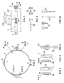
- Figure 1 illustrates a shaft 100 of a rotary cutter device (not shown for clarity).
- the shaft 100 carries a rotary cutter head 101 through which nylon line is usually guided to provide a cutting head.
- a cutting head embodying the present invention is shown attached to the rotary cutter head 101.
- the cutting head is designed to allow the use of filamentary cutting elements on a domestic-sized electric rotary cutter, without the need for extensive or complicated adjustments to be made to the rotary cutter. It will be
- the cutting head of the present invention could be applied to any size or type of rotary cutter device.
- the cutting head embodying one aspect of the present invention comprises a band 1 of cutting head embodying one aspect of the present invention comprises a band 1 of material, for example a flexible metal strip, or other suitable material.
- the band can be provided by a type of clamp that is used for clamping water pipes in automotive and industrial applications.
- the cutting head is shown in plan view in Figure 2.
- the band 1 is secured around the rotary cutter head 101 using a fixing arrangement 2, such as a nut and bolt, or other fixing device such as a flip over fixing clamp.
- the arrangement 2 ensures that the cutting head is securely attached to the rotary cutter head 101.
- a counterweight 6 is secured, using a rivet 7 (or other suitable fastening) to the band 1 directly opposite to the arrangement 2.
- the counterweight serves to reduce vibration when the device is in use.
- each free end of the band can be provided with a rotatable fixing based on the use of a tapped section of round bar, with a screw holding the two sections together.
- the band can be manufactured in two parts, and secured around the head using welding or riveting.
- the band may also be provided by a solid wire or a stranded cable.
- Different types of filament holder 4 and 5 are shown attached to the band 1.
- Each of the holders 4 and 5 is attached to the band 1 using a long shouldered rivet 8, and a washer 9, and by a shorter shouldered rivet 11, and a washer 9.
- the shorter rivet 11 is used solely to secure the holder 4 or 5 to the band 1.
- the long rivet 8 is used to orient the band 1 about the rotary cutter head 101, and to prevent rotation of the band relative to the rotary cutter head 101.
- the longer rivets 8 extend into the guide apertures in the rotary cutter head formerly used to guide the nylon cutting thread, thereby aligning and securing the holders 4 and 5 at a desired location around the cutting head.
- the longer rivets 8 may be provided with a threaded end portion so that the assembly can be secured by a nut inside the rotary cutter head 101.
- the holders 4 and 5 are used to hold respective different types of cutter elements. It will be readily appreciated that the different holders are shown for illustrative purposes will be discussed below with reference to Figures 6 and 7.
- the cutting elements are held between a pair of substantially planar holder members which extend outwardly from the band 1, substantially parallel to one another.
- a cutting head embodying the present invention may be used on various sizes of rotary cutter head 101.
- the securing arrangement 2 enables different sizes of rotary cutter head to be accommodated. However, it is then necessary to provide some adjustment for the position of the cutting element holders, in order to reduce the amount if vibration that occurs when the device is in use.
- the holders should be evenly spaced around the diameter of the rotary cutter head 101. For example, when two holders are used, then they should be placed 180° to one another. This may be achieved by using existing nylon outlet holes already moulded into the trimmer head as these holes are typically at 180 degrees to one another.
- Figure 3, 4 and 5 illustrate respective techniques for providing position adjustments for the holders.
- Figure 3 shows a first technique in which slots 19 are provided in the band 1.
- the slots 19 extend longitudinally along the band 1.
- the holder 4 or 5 is provided on a plate which defines apertures 18 through which fastenings, such as rivets 8 and 11, are received for securing the holder 4 or 5 to the band 1.
- the fastenings 8 and 11 extend through the apertures 18 and through the slots 19, and can be secured at varying position along the slots 19. In this way, the position of the holder 4 or 5 can be adjusted with respect to the band.
- two holders 4 or 5 are provided, and at least one of those features an adjustable fastening.
- Figure 4 shows an alternative adjustment structure, in which the band is provided with elongate slots, which extend longitudinally along the band, and which enable the planar holder members to extend therethrough.
- the holder 4 or 5 can then be secured in an adjusted position by moving the planar holder members relatively to the band.
- Fastening holes 18 are provided in the holder, as before.
- Figure 5 illustrates an alternative fastening technique, in which the holder 4 or 5 is provided with a channel 24 into which the band 1 is located. In this way the position of
- FIG. 6 illustrates a filament cutting element for use with the holder 5 illustrated in Figures 1 and 2.
- This first filament-cutting element comprises a filament portion 22,which has an enlarged end portion. The filament portion is inserted into a hole, which extends through a retaining pin 12.
- the retaining pin 12 is positioned through a pair of retaining holes in the holder 5, and is secured in place using a cotter pin extending through an end region 14 of the retaining pin 12.
- Figures 7, 8, and 9 illustrate alternative fastening methods for attaching filament holders to a rotary cutter head 101.
- a filament cutter holder 30 is simply secured directly to an inner diameter of the cutter head using nuts and bolts 32, or other appropriate fixing.
- the filament cutter holder 30 is attached directly to the outer diameter of the cutter head using a nut and bolt arrangement 32, or other appropriate fixing.
- a securing band may be provided around the holder and the head in order to provide increased security.
- the holder 30 is secured to the head 101 using a band and clamp arrangement 33.
- the clamp 33 can be similar to the type used for securing automotive hoses, sometimes known as a "jubilee clip".
- the holder 30 is secured using a band as previously described with reference to Figure 1, with the addition of an adjustable block 36 on which the holder 30 is mounted.
- the adjustable block 36 is used to adjust the position of the holder 30.
- the cutting element holder 30 comprises a pair 34, 35 of substantially planar portions which extend outwardly.
- a first 34 of the planar portions preferably the upper when the head is in use, defines an aperture in the form of a substantially circular part 40 with a slot 41 that extends to an edge of the planar portion 34.
- the slot 41 extends in a direction substantially tangential to the cutter head 101, and preferably in the direction of rotation of the head. This serves to ensure that the cutting element remains in place during use.
- the circular part 40 of the aperture is of a diameter greater than that of an enlarged head portion of a filamentary cutter.
- the slot 41 has a width greater than the diameter of a filamentary part of the cutter.
- the second 35 of the planar portion defines a substantially circular aperture 42, which is of a diameter smaller than the diameter of the enlarged head portion of a filamentary cutting element.
- the first and second planar portions 34, 35 are spaced apart by a distance smaller than the diameter of the enlarged head of the filamentary cutting element.
- a filamentary cutting element having an enlarged head portion is inserted into the holder 30 by passing the head portion through the substantially circular aperture of the first planar portion held in place in the holder 30.
- the filamentary portion of the cutting element is then allowed to pass through the slot, and the cutting element is rotated so as to project outwardly from the holder 30.
- the cutting element is held in place since the distance between the first and second planar portions is less than the diameter of the cutting element enlarged head.
- Figure 10 illustrates a filamentary cutting element for use with the holder 4 shown in the previous Figures.
- the cutting element 17 of Figure 10 is made up of two pieces: firstly, an extruded filament portion provided with a slightly enlarged end region, and, secondly, a moulded enlarged head portion.
- the filament portion can be provided with the slightly enlarged end region by forming the filament material during extrusion, or by attaching a collar to the end region, for example by crimping.
- the head portion 16 comprises, in this example, a shank portion and an integrally formed ball head portion. In another example, the head portion 16 comprises just the ball portion, and in another, the shank portion and ball portion are separate from one another.
- the head portion 16 defines a countersunk hole which extends longitudinally therethrough, for receiving the filament portion.
- the cutting element is then completed by locating the filament portion in the countersunk hole of the head portion in order to form an enlarged head cutting element suitable for use with the holder 4.
- the cutting element 17 of Figure 10 is held in place in the cutting head by inserting it through one of the holder apertures in the holder portions of the holder 4.
- the planar holder portions are spaced apart by less than the diameter of the enlarged head of the cutting element, such that the holder portion are able to hold the element in place, whilst enabling the element to pivot in multiple directions.
- the enlarged head filament-cutting element may be manufactured by over-moulding thee enlarged head portion onto an extruded filament portion. This has the significant advantage that the filamentary portion can have increased strength by virtue of being extruded, and the enlarged head portion can be securely attached to the filamentary portion in a simple operation.
- the cutting head embodying one aspect of the present invention enables high performance cutting elements to be used on existing spool fed rotary cutters, without the need for extensive modification to the rotary cutter head.
- a filament cutting element embodying another aspect of the present invention provides an improved element, which makes uses of a stronger extruded filamentary portion, combined with the convenience of the enlarged head design.
- the band 1 is provided in two parts, and incorporates two attachment arrangements 2.
- the counterweight 6 would then be omitted, as the two attachment arrangements 2 would counterbalance one another.
- the band may be provided with a series of linked portions which can be removed or added in order to adjust the basic size of the assembly. Such a design enables a greater degree of flexibility for the assembly to fit differently sized cutter heads.
- the holder members 4 and 5 can be secured directly with the cutter head 101, for example using rivets.
Landscapes
- Life Sciences & Earth Sciences (AREA)
- Environmental Sciences (AREA)
- Harvester Elements (AREA)
- Details Of Cutting Devices (AREA)
Applications Claiming Priority (1)
| Application Number | Priority Date | Filing Date | Title |
|---|---|---|---|
| GB0616650A GB2441102A (en) | 2006-08-22 | 2006-08-22 | Rotary head assembly |
Publications (2)
| Publication Number | Publication Date |
|---|---|
| EP1891850A2 true EP1891850A2 (de) | 2008-02-27 |
| EP1891850A3 EP1891850A3 (de) | 2008-04-02 |
Family
ID=37102662
Family Applications (1)
| Application Number | Title | Priority Date | Filing Date |
|---|---|---|---|
| EP07253322A Withdrawn EP1891850A3 (de) | 2006-08-22 | 2007-08-22 | Rotationsschneidemaschinen |
Country Status (6)
| Country | Link |
|---|---|
| US (2) | US20080196254A1 (de) |
| EP (1) | EP1891850A3 (de) |
| AU (1) | AU2007211883A1 (de) |
| CA (1) | CA2598263A1 (de) |
| GB (2) | GB2441102A (de) |
| ZA (1) | ZA200707110B (de) |
Families Citing this family (6)
| Publication number | Priority date | Publication date | Assignee | Title |
|---|---|---|---|---|
| US8028948B1 (en) * | 2008-11-28 | 2011-10-04 | Fly Fishing Xtreme, LLC | Fishing line control system |
| DE102013224781B3 (de) | 2013-12-03 | 2015-03-05 | WAKU GmbH | Vorrichtung zum Aufbewahren und Bereitstellen von Angelschnur |
| US9854738B2 (en) | 2015-05-15 | 2018-01-02 | Black & Decker, Inc. | String trimmer with adjustable guard assembly |
| CN105850341B (zh) * | 2016-04-26 | 2018-02-09 | 刘发 | 一种夏枯草收割剪穗全自动一体机 |
| US11968934B2 (en) * | 2020-02-13 | 2024-04-30 | Edward Tybuszynski | Lawn trimmer attachment for trimming sprinkler heads |
| CN117452415B (zh) * | 2023-12-26 | 2024-03-15 | 国家海洋局北海海洋工程勘察研究院 | 一种水下附着生物探测器 |
Family Cites Families (20)
| Publication number | Priority date | Publication date | Assignee | Title |
|---|---|---|---|---|
| US568905A (en) * | 1896-10-06 | Towel-rack | ||
| US1801158A (en) * | 1930-05-31 | 1931-04-14 | Alfred H Howe | Towel rack |
| US2706023A (en) * | 1952-01-02 | 1955-04-12 | Ronald A Merritt | Gripping device for securing guy wires to a mast |
| US4019704A (en) * | 1975-05-28 | 1977-04-26 | Acme Service Corporation | Motor mounting structure |
| US4189905A (en) * | 1978-02-24 | 1980-02-26 | Corinth Co. Inc. | Attachment for drive shaft of rotary lawn mowers |
| US4572472A (en) * | 1982-06-02 | 1986-02-25 | Westinghouse Electric Corp. | Electric motor flexible mounting system and method of assembly |
| USRE32629E (en) * | 1983-02-08 | 1988-03-29 | Kioritz Corporation | Mowing machine with annular inertia shifter |
| US4513563A (en) * | 1983-02-23 | 1985-04-30 | Carl A. Roser | Lawn mower rotary assembly |
| US4756146A (en) * | 1987-02-18 | 1988-07-12 | Snapper Power Equipment Division Of Fuqua Industries, Inc. | String trimmer head and method |
| US4827702A (en) * | 1988-03-14 | 1989-05-09 | Cerreta Jonathan D | Blower attachment for filament trimmers |
| CA1286116C (en) * | 1988-07-14 | 1991-07-16 | Axel U.R. Truderung | Lawn mower cutting assembly |
| US5069415A (en) * | 1990-07-25 | 1991-12-03 | Emmanuel Mechalas | Adjustable mounting assembly for electric motors |
| US5470207A (en) * | 1993-07-26 | 1995-11-28 | L & S Bearing Co. | Apparatus and method for providing universal automative air conditioning compressor |
| EP0683969B1 (de) * | 1994-05-25 | 2000-03-08 | Easytrim Ltd | Rotationsmäher |
| US6314848B2 (en) * | 1998-02-17 | 2001-11-13 | Vincent D. Morabit | Self-contained flexible aerodynamic cutting element with matching head |
| US6052974A (en) * | 1999-10-14 | 2000-04-25 | Harb; Mitchell A. | Adjustable height head for string trimmer |
| US6643938B2 (en) * | 2001-08-17 | 2003-11-11 | Robert J. Livingston | Replacement cutting attachment for string trimmer |
| EP1511372B1 (de) * | 2002-06-07 | 2010-08-04 | Speed France S.A.S. | Mähfaden für vegetation-mähapparat |
| US7603782B2 (en) * | 2004-12-01 | 2009-10-20 | Orlando Jerez | Universal, trimmer line, hook disk system |
| DE102005031778A1 (de) * | 2005-07-07 | 2007-01-11 | Andreas Stihl Ag & Co. Kg | Schneidkopf für einen Freischneider |
-
2006
- 2006-08-22 GB GB0616650A patent/GB2441102A/en not_active Withdrawn
-
2007
- 2007-08-21 CA CA002598263A patent/CA2598263A1/en not_active Abandoned
- 2007-08-22 US US11/843,180 patent/US20080196254A1/en not_active Abandoned
- 2007-08-22 AU AU2007211883A patent/AU2007211883A1/en not_active Abandoned
- 2007-08-22 ZA ZA200707110A patent/ZA200707110B/en unknown
- 2007-08-22 EP EP07253322A patent/EP1891850A3/de not_active Withdrawn
- 2007-08-22 GB GB0716375A patent/GB2441223A/en not_active Withdrawn
-
2011
- 2011-12-08 US US13/314,483 patent/US20120079727A1/en not_active Abandoned
Also Published As
| Publication number | Publication date |
|---|---|
| CA2598263A1 (en) | 2008-02-22 |
| US20120079727A1 (en) | 2012-04-05 |
| US20080196254A1 (en) | 2008-08-21 |
| EP1891850A3 (de) | 2008-04-02 |
| GB0616650D0 (en) | 2006-10-04 |
| GB0716375D0 (en) | 2007-10-03 |
| AU2007211883A1 (en) | 2008-03-13 |
| GB2441223A (en) | 2008-02-27 |
| GB2441102A (en) | 2008-02-27 |
| ZA200707110B (en) | 2009-09-30 |
Similar Documents
| Publication | Publication Date | Title |
|---|---|---|
| US20120079727A1 (en) | Rotary cutters | |
| US7127877B2 (en) | Universal mower blade | |
| US6944956B1 (en) | Fixed-line trimmer head | |
| EP2029925B1 (de) | Klammerelement zum halten zumindest eines gegenstands, insbesondere eines kabels | |
| DE19828073C1 (de) | Kabelhalter aus Kunststoff für Fahrzeuge | |
| US7581847B2 (en) | Clip-on, clip off mounting device, as for a portable light | |
| US8740529B2 (en) | Attaching arrangement for hand-held motor-driven tools | |
| US10531609B2 (en) | Spring biased receptacle for rotary head assembly | |
| CN105526223B (zh) | 紧固元件以及具有所述紧固元件和接收元件的组件 | |
| US20150201557A1 (en) | Ramped Connector And Blade For Use With Rotary Head Assembly | |
| US9556974B2 (en) | System for guiding and securing the position of strand elements | |
| WO2016063268A1 (en) | Fixed line pivoting trimmer heads pivoting concepts | |
| US11840859B2 (en) | Wire strand attachment clip | |
| US7909378B2 (en) | Apparatus for carrying multiple fishing poles | |
| EP2167280B1 (de) | Befestigungsmechanismus | |
| US20180027789A1 (en) | Method and device to prevent tangling of a fishing line | |
| US20170105341A1 (en) | Monofilament line holder for grass trimmers | |
| US20200229413A1 (en) | Fish hook threading accessory | |
| EP3022449B1 (de) | Befestigung von kanalelementen | |
| CA2733603A1 (en) | Offset guard bolt attachment system | |
| JP2015156737A (ja) | バンドクリップ | |
| JP6430817B2 (ja) | 取着体、取着具及び配線・配管材固定装置 | |
| JP6325436B2 (ja) | 支持装置、取着体及びボルト体立設装置 | |
| DE202005018133U1 (de) | Halter zur Befestigen eines Kabelbandes o.dgl. | |
| EP1459002A1 (de) | Stützvorrichtung zur befestigung von rohren und kabeln an einem fahrzeug mit einer mit einer konvexen hüllfläche versehenen konsole |
Legal Events
| Date | Code | Title | Description |
|---|---|---|---|
| PUAI | Public reference made under article 153(3) epc to a published international application that has entered the european phase |
Free format text: ORIGINAL CODE: 0009012 |
|
| AK | Designated contracting states |
Kind code of ref document: A2 Designated state(s): AT BE BG CH CY CZ DE DK EE ES FI FR GB GR HU IE IS IT LI LT LU LV MC MT NL PL PT RO SE SI SK TR |
|
| AX | Request for extension of the european patent |
Extension state: AL BA HR MK YU |
|
| PUAL | Search report despatched |
Free format text: ORIGINAL CODE: 0009013 |
|
| AK | Designated contracting states |
Kind code of ref document: A3 Designated state(s): AT BE BG CH CY CZ DE DK EE ES FI FR GB GR HU IE IS IT LI LT LU LV MC MT NL PL PT RO SE SI SK TR |
|
| AX | Request for extension of the european patent |
Extension state: AL BA HR MK YU |
|
| AKX | Designation fees paid | ||
| REG | Reference to a national code |
Ref country code: DE Ref legal event code: 8566 |
|
| STAA | Information on the status of an ep patent application or granted ep patent |
Free format text: STATUS: THE APPLICATION IS DEEMED TO BE WITHDRAWN |
|
| 18D | Application deemed to be withdrawn |
Effective date: 20081003 |