EP1891907A1 - Dispositif destiné à la résection et/ou l'ablation de tissus organiques à l'aide d'une énergie haute fréquence tout comme résectoscope - Google Patents
Dispositif destiné à la résection et/ou l'ablation de tissus organiques à l'aide d'une énergie haute fréquence tout comme résectoscope Download PDFInfo
- Publication number
- EP1891907A1 EP1891907A1 EP07015075A EP07015075A EP1891907A1 EP 1891907 A1 EP1891907 A1 EP 1891907A1 EP 07015075 A EP07015075 A EP 07015075A EP 07015075 A EP07015075 A EP 07015075A EP 1891907 A1 EP1891907 A1 EP 1891907A1
- Authority
- EP
- European Patent Office
- Prior art keywords
- loop
- connecting element
- cutting edge
- carrier
- wedge
- Prior art date
- Legal status (The legal status is an assumption and is not a legal conclusion. Google has not performed a legal analysis and makes no representation as to the accuracy of the status listed.)
- Granted
Links
- 238000002679 ablation Methods 0.000 title claims description 7
- 238000002271 resection Methods 0.000 title claims description 7
- 230000005611 electricity Effects 0.000 title 1
- 238000005520 cutting process Methods 0.000 claims description 49
- 208000004403 Prostatic Hyperplasia Diseases 0.000 description 2
- 206010046798 Uterine leiomyoma Diseases 0.000 description 2
- 230000001154 acute effect Effects 0.000 description 2
- 238000005345 coagulation Methods 0.000 description 2
- 230000015271 coagulation Effects 0.000 description 2
- 201000010260 leiomyoma Diseases 0.000 description 2
- 239000007788 liquid Substances 0.000 description 2
- 229910000831 Steel Inorganic materials 0.000 description 1
- 241000673677 Viburnum lantana Species 0.000 description 1
- 238000005452 bending Methods 0.000 description 1
- 230000015572 biosynthetic process Effects 0.000 description 1
- 230000000740 bleeding effect Effects 0.000 description 1
- 150000001875 compounds Chemical class 0.000 description 1
- 210000004696 endometrium Anatomy 0.000 description 1
- 238000011010 flushing procedure Methods 0.000 description 1
- 239000007787 solid Substances 0.000 description 1
- 239000010959 steel Substances 0.000 description 1
- 238000011477 surgical intervention Methods 0.000 description 1
- 238000001356 surgical procedure Methods 0.000 description 1
Images


Classifications
-
- A—HUMAN NECESSITIES
- A61—MEDICAL OR VETERINARY SCIENCE; HYGIENE
- A61B—DIAGNOSIS; SURGERY; IDENTIFICATION
- A61B18/00—Surgical instruments, devices or methods for transferring non-mechanical forms of energy to or from the body
- A61B18/04—Surgical instruments, devices or methods for transferring non-mechanical forms of energy to or from the body by heating
- A61B18/12—Surgical instruments, devices or methods for transferring non-mechanical forms of energy to or from the body by heating by passing a current through the tissue to be heated, e.g. high-frequency current
- A61B18/14—Probes or electrodes therefor
-
- A—HUMAN NECESSITIES
- A61—MEDICAL OR VETERINARY SCIENCE; HYGIENE
- A61B—DIAGNOSIS; SURGERY; IDENTIFICATION
- A61B18/00—Surgical instruments, devices or methods for transferring non-mechanical forms of energy to or from the body
- A61B2018/00571—Surgical instruments, devices or methods for transferring non-mechanical forms of energy to or from the body for achieving a particular surgical effect
- A61B2018/00601—Cutting
-
- A—HUMAN NECESSITIES
- A61—MEDICAL OR VETERINARY SCIENCE; HYGIENE
- A61B—DIAGNOSIS; SURGERY; IDENTIFICATION
- A61B18/00—Surgical instruments, devices or methods for transferring non-mechanical forms of energy to or from the body
- A61B18/04—Surgical instruments, devices or methods for transferring non-mechanical forms of energy to or from the body by heating
- A61B18/12—Surgical instruments, devices or methods for transferring non-mechanical forms of energy to or from the body by heating by passing a current through the tissue to be heated, e.g. high-frequency current
- A61B18/14—Probes or electrodes therefor
- A61B2018/1405—Electrodes having a specific shape
- A61B2018/1407—Loop
-
- A—HUMAN NECESSITIES
- A61—MEDICAL OR VETERINARY SCIENCE; HYGIENE
- A61B—DIAGNOSIS; SURGERY; IDENTIFICATION
- A61B18/00—Surgical instruments, devices or methods for transferring non-mechanical forms of energy to or from the body
- A61B18/04—Surgical instruments, devices or methods for transferring non-mechanical forms of energy to or from the body by heating
- A61B18/12—Surgical instruments, devices or methods for transferring non-mechanical forms of energy to or from the body by heating by passing a current through the tissue to be heated, e.g. high-frequency current
- A61B18/14—Probes or electrodes therefor
- A61B2018/1405—Electrodes having a specific shape
- A61B2018/1435—Spiral
-
- A—HUMAN NECESSITIES
- A61—MEDICAL OR VETERINARY SCIENCE; HYGIENE
- A61B—DIAGNOSIS; SURGERY; IDENTIFICATION
- A61B18/00—Surgical instruments, devices or methods for transferring non-mechanical forms of energy to or from the body
- A61B18/04—Surgical instruments, devices or methods for transferring non-mechanical forms of energy to or from the body by heating
- A61B18/12—Surgical instruments, devices or methods for transferring non-mechanical forms of energy to or from the body by heating by passing a current through the tissue to be heated, e.g. high-frequency current
- A61B18/14—Probes or electrodes therefor
- A61B2018/1405—Electrodes having a specific shape
- A61B2018/144—Wire
-
- A—HUMAN NECESSITIES
- A61—MEDICAL OR VETERINARY SCIENCE; HYGIENE
- A61B—DIAGNOSIS; SURGERY; IDENTIFICATION
- A61B18/00—Surgical instruments, devices or methods for transferring non-mechanical forms of energy to or from the body
- A61B18/18—Surgical instruments, devices or methods for transferring non-mechanical forms of energy to or from the body by applying electromagnetic radiation, e.g. microwaves
- A61B18/1815—Surgical instruments, devices or methods for transferring non-mechanical forms of energy to or from the body by applying electromagnetic radiation, e.g. microwaves using microwaves
- A61B2018/1861—Surgical instruments, devices or methods for transferring non-mechanical forms of energy to or from the body by applying electromagnetic radiation, e.g. microwaves using microwaves with an instrument inserted into a body lumen or cavity, e.g. a catheter
Definitions
- the invention relates to a device for resection and / or ablation of organic tissue by means of high-frequency current, with a loop carrier, with an acted upon by high frequency voltage loop, which is arranged at a distal end of the loop carrier, and with a connecting element between the loop and the loop carrier.
- the invention further relates to a resectoscope for ablating organic tissue by means of high-frequency current, with a shaft in which a device of the aforementioned type is arranged.
- Such a device is for example from the US 2004/0064139 A1 known.
- Such a device or a resectoscope is used in high-frequency surgery for resection and ablation of organic tissue.
- the device can be used in hysteroscopy or in urology to remove fibroids, polyps and tissue of the endometrium or prostatic adenomas.
- the known device has a loop carrier, an electrically conductive and acted upon by high-frequency current loop and a connecting element in the form of two straight strands between the loop carrier and the loop on.
- the loop extends either in a plane transverse to a longitudinal axis of the loop carrier or in a plane containing the longitudinal axis of the loop carrier.
- a loop carrier in the form of a hollow tube, a distal side of the loop carrier arranged loop and designed as a double helix Has connecting element between the loop and the loop carrier.
- the loop is semicircular and slightly inclined against a longitudinal axis of the loop carrier and acted upon by high-frequency voltage.
- tissue is cut by the loop and the double helix is set in rotation about the longitudinal axis of the hollow tube.
- the co-rotating double helix is also intended to serve for the transport of cut organic tissue to the proximal, wherein the tissue can be additionally sucked in the proximal direction when it is inserted into the tube.
- the semicircular loop at the beginning of the cut is more or less linear on the tissue, and it may happen that individual loop sections touch the tissue, but not others. This is the case when the tissue to be cut has convex and concave areas. In other words, there is no defined point at the noose at which the cut begins. Due to the at least partially line-shaped abutment of the loop on the tissue to be cut and the cutting action of the known device is not optimal. The same is true for the off US 2004/0064139 A1 Known device in which the loop due to their symmetry does not allow a defined gate.
- the object with regard to the device mentioned in the introduction is achieved in that a loop end section of the loop and a distal connecting element section of the connecting element form a wedge-shaped cutting edge.
- the device according to the invention therefore has a wedge-shaped cutting edge at its distal end.
- “Wedge-shaped” here means that the distal connecting element section and the loop end section converge at an acute angle, ie an angle of less than 90 °. This compound is preferable integrally.
- the wedge-shaped cutting edge is particularly suitable for an embodiment of the device in which the loop is set in rotation for cutting.
- the wedge-shaped blade forms a defined punctiform contact of the effective cutting area of the loop on the tissue. Due to the wedge-shaped design of the cutting edge, this can effectively penetrate into the tissue to be cut while at the same time detaching or lifting off the tissue to be separated from the remaining tissue.
- the device according to the invention advantageously enables the resection and coagulation of tissue located frontally in front of the loop as well as of that which is located laterally of the connection element or the loop.
- the tissue located at the front is removed by the loop end section and the remaining region of the loop, while the tissue located laterally can be removed at least through the distal connection element section.
- the loop extends in a plane transverse to a longitudinal axis of the loop carrier.
- This measure has the advantage that in the event that the loop is displaceable in rotation via the loop carrier, the loop, which is usually formed from a thin wire, cuts like a sickle in the longitudinal extent of the wire through the tissue. As a result, the loop undergoes no increased mechanical resistance during cutting and is less subject to the risk of bending or even breaking.
- loop carrier is rotatable about its longitudinal axis and an end portion of the wedge-shaped cutting edge points in the direction of rotation of the loop carrier.
- the wedge-shaped cutting edge forms the leading end of the loop when the loop carrier is rotated about its longitudinal axis.
- the wedge-shaped cutting edge can thus be effectively inserted into the tissue Separate the same penetrate.
- the wedge-shaped configuration of the cutting edge effectively separates the tissue in cooperation with the remaining trailing portion of the loop.
- the wedge-shaped cutting edge points slightly distally.
- This measure has the advantage that due to the slight inclination, the wedge-shaped cutting edge pulls distally like a screw into the tissue, which means that no or no substantial pressure in the feed direction has to be exerted during cutting.
- the connecting element is helical.
- This measure has the advantage that the device has a compact design on the distal side, and that the stability of the device is increased. Furthermore, laterally located tissue can be removed continuously in addition to the tissue adjacent to the area of the turns in the manner of a corkscrew-like sickle. This is particularly advantageous when compared to a straight configuration of the connecting element, since the surgical intervention can be carried out more quickly. As long as the severed tissue is not yet completely separated, the helical configuration causes the tissue to be conveyed proximally due to a relative movement to the connecting element.
- the connecting element comprises a first strand and a second strand, wherein a distal end portion of the first strand forms the wedge-shaped edge with the loop end portion, and a distal end portion of the second strand is connected to the loop end of the loop opposite the loop end portion.
- This measure has the advantage that the stability of the connecting element against external forces during the cutting process is increased, since the loop is connected not only in the region of the wedge-shaped cutting edge with the connecting element, but also at a second end, so that they in particular against torsional forces, the when rotating with the sling occur, is torsionally stiff.
- first strand and the second strand of the connecting element are wound helically in opposite directions.
- the loop is approximately semicircular.
- This measure which is known per se, in combination with the formation of a wedge-shaped cutting edge on the one loop end section, has the advantage of a particularly efficient cutting action of the loop, since the further cutting region of the loop is sufficiently large.
- the loop on the inside and / or outside a cutting edge.
- This measure has the advantage that the loop not only acts in the area of the wedge-shaped cutting edge, but also in its remaining area, whereby the cutting efficiency of the device according to the invention is further improved.
- the connecting element has a cutting edge on the inside and / or outside at least in the area of the distal connecting element section.
- the cutting edge of the connecting element section which is preferably arranged on the outside and on the inside, engages in the tissue to be ablated and cuts it in a sharp cut.
- the loop carrier is designed as a hollow tube.
- This measure has the advantage that tissue separated by means of the loop and possibly the connecting element can be removed from the body through the hollow tube, for example by applying a suction flow to the proximal end of the hollow tube. In this way, the separated tissue is permanently removed from the body, without the separated tissue must be removed by means of an additional instrument.
- the resectoscope according to the invention has a device according to one or more of the aforementioned embodiments.
- a provided with the general reference numeral 10 device for resection and / or ablation of organic tissue is shown by means of high-frequency current.
- the device 10 can be used, for example, in hysteroscopy or urology to remove fibroids, polyps and Endrometriumsgewebe or prostatic adenomas.
- the apparatus 10 has a loop carrier 12, at the distal end 14 of which a connecting element 16 and a loop 18 which can be acted upon by high-frequency voltage are arranged.
- the loop carrier 12 is designed as a cylindrical hollow tube, wherein the connecting element 16 is connected to an annular end face of the distal end 14 of the hollow tube.
- a distal connector portion 20 of the connector 16 is connected in a wedge shape to a loop end portion 22 of the sling 18, i. the connecting element portion 20 and the loop end portion converge at an acute angle of less than 90 °.
- At least the distal connecting element section 20, like the loop 18, has a current-carrying design and is not insulated on the outside.
- the connecting member portion 20 is a distal end portion 24 of a first strand 26 of the connecting member 16, wherein the first strand 26 is connected at a proximal end 28 with the distal end 14 of the loop carrier 12.
- the connecting element 16 also has a second strand 30 which is arranged between the distal end 14 of the loop carrier 12 and a loop end 32 of the loop 18.
- a proximal end 33 of the second strand 30 is connected to the distal end 14 of the loop carrier 12 at a position offset by about 180 ° from the junction of the first strand 26 to the distal end 14 of the loop carrier 12, and a distal end region 34 of the second strand 30 is connected to the loop end 32.
- the loop end portion 22 and the distal end portion 24 of the first strand 26 are acute-angled, i. connected at a small angle of less than 90 °.
- the loop 18 and the strands 26, 30 are formed wire-shaped.
- the connecting element 16 is helically formed, wherein both strands 26, 30 are helically wound in opposite directions, ie they have each seen in a longitudinal direction 36 of the loop carrier 12 by half a pitch offset opposing turns on. Each strand 26, 30 has a half turn.
- the two strands 26, 30 of the connecting element 16 may also have a plurality of turns.
- the loop 18 extends in a plane transverse to the longitudinal axis 36 of the loop carrier 12. In the embodiment shown, the loop 18 extends in the plane approximately perpendicular to the longitudinal axis 36 of the loop carrier 12. A corner 38 in the region of the connection of the connecting element section 20 with the Loop end portion 22 forms a wedge-shaped cutting edge 40 which lies in the plane of the loop 18. Likewise, the wedge-shaped cutting edge 40 can point slightly distally, for which purpose also the plane in which the loop extends may deviate from a vertical arrangement with respect to the longitudinal axis 36 of the loop carrier 12. The wedge-shaped cutting edge 40 can, as shown here, be rounded or tapered.
- the loop 18 is approximately semicircular. It may also be formed as an elliptical arc or arc of greater or lesser extent than about 180 °.
- the loop 18 may have a cutting edge on the inside and / or outside or be designed as a cutting blade.
- the cutting edge or the cutting blade can be directed inwards.
- the connecting element 16 can also have on the inside and / or outside a cutting edge for resecting tissue or be designed as a cutting blade.
- the cutting edge or the cutting blade can extend on the inside over the entire length of the two strands 26, 30, wherein the cutting edge or the cutting blade is aligned tangentially at each position of the strands.
- the loop 18 and the connecting element 16 may be formed from a rigid wire, in particular a steel wire.
- the loop 18 and the connecting element 16 are acted upon by high-frequency voltage and formed electrically conductive.
- the connecting element 16 is electrically contacted on the proximal side.
- the loop carrier 12 is rotatable about its longitudinal axis 36 in a rotational direction along an arrow 42, so that the wedge-shaped cutting edge 40 points in the direction of rotation of the loop carrier 12.
- the wedge-shaped blade 40 precedes and causes the gate, while the further cut of the remaining, trailing portion of the loop 18 is effected.
- tissue located laterally of the connecting element can be removed with the two strands 26, 30.
- FIG. 2A shows a plan view of the connecting element 16 and the loop 18 in FIG. 1.
- the semicircular loop 18 lies in the plane of the drawing, since it extends in the plane approximately perpendicular to the longitudinal axis 36 of the loop carrier 12.
- the semicircular loop 16 has an outer radius 44 approximately equal to an outer radius 46 of the cylindrical connecting element 16, i. the two helical strands 26, 30 corresponds.
- An outer radius of the loop carrier 12 may also be the same or slightly smaller than the outer radius 44, 46, so that the device 10, in particular the connecting element 16, can evenly remove a tissue surface.
- FIGS. 2B-2D show side views of the connecting element 16 and the sling 18 in FIG. 1, FIG. 2B being a view of the loop inside, FIG. 2C on the outside of the loop, and FIG. 2D on the loop end section 22 and the wedge-shaped cutting edge 40.
- 3A-3C show three rotational positions 48-52 of the connecting element 16 and the loop 18 in Fig. 1.
- first rotational position 48 a perspective view of the loop inside is shown and the wedge-shaped cutting edge 40 points out of the plane.
- the loop 18 and the connecting element 16 are further rotated by about 90 ° about the longitudinal axis 36 of the loop carrier 12 along the direction of rotation of the arrow 42.
- second rotational position 50 the loop 18 and the connecting element 16 along the direction of rotation of the arrow 42 are further rotated by about 60 °.
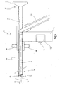
- FIG. 4 shows a resectoscope 54 in which the device 10 is accommodated.
- the device 10 is arranged in a shaft 56 of the resectoscope 54, which is designed as a hollow tube.
- the shaft 56 has an endoscope 58 which extends within the shaft 56 from a distal end 60 of the resectoscope to an eyepiece 62 at a proximal end 64 of the resectoscope 54.
- ports 66, 68 are provided for flushing and suction lines.
- the connections 66, 68 serve to supply a rinsing liquid into the treatment area and to discharge liquid from the treatment area.
- the resectoscope 54 has a handle 70, in which a motor 72 for generating the rotational movement of the device 10 is received.
- the motor 72 is manually by means of a switch 74, shown schematically here as a push button actuated.
- the rotational speed of the loop carrier 12, i. the device 10 can be variably adjusted.
- a suction line 76 to which a suction flow can be applied, is connected to the hollow tubular loop carrier 12, so that separated tissue can be sucked off via the loop carrier 12 and the suction line 76.
- the loop 18 and the connecting element 16 protrude at least partially out of the shaft 56 of the resectoscope 54.
- the helical strands 26, 30 each have a half turn, so that the loop 18 is only slightly spaced from the end of the shaft 56 of the Resektoskops 54. Further, the sling 18 and the connecting element 16 is always arranged within a field of view of the endoscope 58.
Landscapes
- Health & Medical Sciences (AREA)
- Surgery (AREA)
- Engineering & Computer Science (AREA)
- Life Sciences & Earth Sciences (AREA)
- Biomedical Technology (AREA)
- Otolaryngology (AREA)
- Nuclear Medicine, Radiotherapy & Molecular Imaging (AREA)
- Plasma & Fusion (AREA)
- Physics & Mathematics (AREA)
- Heart & Thoracic Surgery (AREA)
- Medical Informatics (AREA)
- Molecular Biology (AREA)
- Animal Behavior & Ethology (AREA)
- General Health & Medical Sciences (AREA)
- Public Health (AREA)
- Veterinary Medicine (AREA)
- Surgical Instruments (AREA)
Applications Claiming Priority (1)
| Application Number | Priority Date | Filing Date | Title |
|---|---|---|---|
| DE102006039696A DE102006039696A1 (de) | 2006-08-21 | 2006-08-21 | Vorrichtung zur Resektion und/oder Ablation von organischem Gewebe mittels Hochfrequenzstrom sowie Resektoskop |
Publications (2)
| Publication Number | Publication Date |
|---|---|
| EP1891907A1 true EP1891907A1 (fr) | 2008-02-27 |
| EP1891907B1 EP1891907B1 (fr) | 2010-10-13 |
Family
ID=38787070
Family Applications (1)
| Application Number | Title | Priority Date | Filing Date |
|---|---|---|---|
| EP07015075A Not-in-force EP1891907B1 (fr) | 2006-08-21 | 2007-08-01 | Dispositif destiné à la résection et/ou l'ablation de tissus organiques à l'aide d'une énergie haute fréquence tout comme résectoscope |
Country Status (3)
| Country | Link |
|---|---|
| US (1) | US8267933B2 (fr) |
| EP (1) | EP1891907B1 (fr) |
| DE (2) | DE102006039696A1 (fr) |
Cited By (1)
| Publication number | Priority date | Publication date | Assignee | Title |
|---|---|---|---|---|
| DE102018125287A1 (de) * | 2018-10-12 | 2020-04-16 | Olympus Winter & Ibe Gmbh | Resektoskop mit Schaftrohrelektrodeninstrument |
Families Citing this family (10)
| Publication number | Priority date | Publication date | Assignee | Title |
|---|---|---|---|---|
| US6814739B2 (en) | 2001-05-18 | 2004-11-09 | U.S. Endoscopy Group, Inc. | Retrieval device |
| US8591521B2 (en) | 2007-06-08 | 2013-11-26 | United States Endoscopy Group, Inc. | Retrieval device |
| DE102009041602A1 (de) | 2009-09-17 | 2011-03-24 | Karl Storz Gmbh & Co. Kg | Medizinischer Resektor |
| DE102009041605A1 (de) | 2009-09-17 | 2011-04-28 | Karl Storz Gmbh & Co. Kg | Medizinischer Resektor mit rotierbarer Hochfrequenz-Eletrode und Antriebseinheit dafür |
| US9572591B2 (en) | 2013-09-03 | 2017-02-21 | United States Endoscopy Group, Inc. | Endoscopic snare device |
| US9872700B2 (en) * | 2013-09-03 | 2018-01-23 | United States Endoscopy Group, Inc. | Endoscopic snare device |
| GB201316287D0 (en) | 2013-09-13 | 2013-10-30 | Gyrus Medical Ltd | Electrode assembly |
| WO2018129551A1 (fr) | 2017-01-09 | 2018-07-12 | United States Endoscopy Group, Inc. | Dispositif de type anse endoscopique |
| DE102017115778A1 (de) | 2017-07-13 | 2019-01-17 | Karl Storz Se & Co. Kg | Medizinisches Instrument zum Abtragen von Gewebe |
| DE102017120341A1 (de) | 2017-09-05 | 2019-03-07 | Karl Storz Se & Co. Kg | Medizinisches Instrument zum Abtragen von Gewebe mittels einer HF-Elektrode mit der Funktion einer kontrollierten distalen Winkelausrichtung |
Citations (6)
| Publication number | Priority date | Publication date | Assignee | Title |
|---|---|---|---|---|
| DE848233C (de) | 1951-03-04 | 1952-09-01 | Eberhard Heynemann | Elektrode zum elektrischen Schneiden in menschlichen Koerperhoehlen |
| US20030130653A1 (en) * | 1997-09-30 | 2003-07-10 | Scimed Life Systems, Inc. | Electrosurgical tissue removal with a selectively insulated electrode |
| US20040064139A1 (en) | 2000-03-30 | 2004-04-01 | Ofer Yossepowitch | Resectoscope |
| US20040138654A1 (en) | 2003-01-09 | 2004-07-15 | Gyrus Medical Limited | Electrosurgical generator |
| US20060089639A1 (en) | 1999-06-22 | 2006-04-27 | Senorx, Inc. | Shaped scalpel |
| WO2006048199A1 (fr) * | 2004-10-29 | 2006-05-11 | Jacques Hamou | Dispositif de resection et/ou d'ablation de tissu organique au moyen d'un courant haute frequence |
Family Cites Families (26)
| Publication number | Priority date | Publication date | Assignee | Title |
|---|---|---|---|---|
| US3955578A (en) * | 1974-12-23 | 1976-05-11 | Cook Inc. | Rotatable surgical snare |
| US5047027A (en) * | 1990-04-20 | 1991-09-10 | Everest Medical Corporation | Tumor resector |
| US5100423A (en) * | 1990-08-21 | 1992-03-31 | Medical Engineering & Development Institute, Inc. | Ablation catheter |
| US5207686A (en) * | 1992-04-15 | 1993-05-04 | Stuart Dolgin | Surgical snare |
| CA2102084A1 (fr) * | 1992-11-09 | 1994-05-10 | Howard C. Topel | Instrument tranchant chirurgical pour l'exerese de tissus fixes |
| US5957923A (en) * | 1995-04-20 | 1999-09-28 | Symbiosis Corporation | Loop electrodes for electrocautery probes for use with a resectoscope |
| US6013076A (en) * | 1996-01-09 | 2000-01-11 | Gyrus Medical Limited | Electrosurgical instrument |
| US6246913B1 (en) * | 1997-02-14 | 2001-06-12 | Oractec Interventions, Inc. | Method and apparatus for the treatment of strabismus |
| US5906615A (en) * | 1997-03-31 | 1999-05-25 | Femrx, Inc. | Serpentine ablation/coagulation electrode |
| US6245067B1 (en) * | 1997-04-16 | 2001-06-12 | Irvine Biomedical, Inc. | Ablation device and methods having perpendicular electrodes |
| US6454727B1 (en) * | 1998-03-03 | 2002-09-24 | Senorx, Inc. | Tissue acquisition system and method of use |
| US6093185A (en) * | 1998-03-05 | 2000-07-25 | Scimed Life Systems, Inc. | Expandable PMR device and method |
| US6537248B2 (en) | 1998-07-07 | 2003-03-25 | Medtronic, Inc. | Helical needle apparatus for creating a virtual electrode used for the ablation of tissue |
| US6050993A (en) * | 1998-07-27 | 2000-04-18 | Quantum Therapeutics Corp. | Medical device and methods for treating hemorrhoids |
| JP2000083963A (ja) * | 1998-09-14 | 2000-03-28 | Asahi Optical Co Ltd | 内視鏡用スネア |
| US6217575B1 (en) * | 1999-02-24 | 2001-04-17 | Scimed Life Systems, Inc. | PMR catheter |
| US6494888B1 (en) * | 1999-06-22 | 2002-12-17 | Ndo Surgical, Inc. | Tissue reconfiguration |
| DE29911756U1 (de) * | 1999-07-09 | 1999-11-18 | Karl Storz GmbH & Co., 78532 Tuttlingen | Schneideschlingen-Elektrode für ein medizinisches Hochfrequenzinstrument |
| US6607520B2 (en) * | 1999-09-15 | 2003-08-19 | The General Hospital Corporation | Coiled ablation catheter system |
| DE10042095C1 (de) * | 2000-08-26 | 2002-01-17 | Winter & Ibe Olympus | Urologisches Resektoskop mit Kontaktiereinrichtung |
| US6743228B2 (en) * | 2001-09-12 | 2004-06-01 | Manoa Medical, Inc. | Devices and methods for tissue severing and removal |
| CA2463400A1 (fr) * | 2001-10-12 | 2003-04-24 | Applied Medical Resources Corporation | Systeme de panier de recuperation de calcul a debit de fluide eleve |
| US6997926B2 (en) * | 2002-02-04 | 2006-02-14 | Boston Scientific Scimed, Inc. | Resistance heated tissue morcellation |
| US7270663B2 (en) * | 2003-10-16 | 2007-09-18 | Granit Medical Innovations, Llc | Medical snare loop with indentations for changing effective size of loop and associated method |
| JP4296082B2 (ja) * | 2003-12-10 | 2009-07-15 | Hoya株式会社 | 内視鏡用高周波スネア |
| DE102005013847B4 (de) * | 2005-03-24 | 2009-08-06 | Erbe Elektromedizin Gmbh | Elektrochirurgisches Instrument |
-
2006
- 2006-08-21 DE DE102006039696A patent/DE102006039696A1/de not_active Withdrawn
-
2007
- 2007-08-01 EP EP07015075A patent/EP1891907B1/fr not_active Not-in-force
- 2007-08-01 DE DE502007005324T patent/DE502007005324D1/de active Active
- 2007-08-21 US US11/842,592 patent/US8267933B2/en not_active Expired - Fee Related
Patent Citations (6)
| Publication number | Priority date | Publication date | Assignee | Title |
|---|---|---|---|---|
| DE848233C (de) | 1951-03-04 | 1952-09-01 | Eberhard Heynemann | Elektrode zum elektrischen Schneiden in menschlichen Koerperhoehlen |
| US20030130653A1 (en) * | 1997-09-30 | 2003-07-10 | Scimed Life Systems, Inc. | Electrosurgical tissue removal with a selectively insulated electrode |
| US20060089639A1 (en) | 1999-06-22 | 2006-04-27 | Senorx, Inc. | Shaped scalpel |
| US20040064139A1 (en) | 2000-03-30 | 2004-04-01 | Ofer Yossepowitch | Resectoscope |
| US20040138654A1 (en) | 2003-01-09 | 2004-07-15 | Gyrus Medical Limited | Electrosurgical generator |
| WO2006048199A1 (fr) * | 2004-10-29 | 2006-05-11 | Jacques Hamou | Dispositif de resection et/ou d'ablation de tissu organique au moyen d'un courant haute frequence |
Cited By (1)
| Publication number | Priority date | Publication date | Assignee | Title |
|---|---|---|---|---|
| DE102018125287A1 (de) * | 2018-10-12 | 2020-04-16 | Olympus Winter & Ibe Gmbh | Resektoskop mit Schaftrohrelektrodeninstrument |
Also Published As
| Publication number | Publication date |
|---|---|
| US20080045945A1 (en) | 2008-02-21 |
| DE502007005324D1 (de) | 2010-11-25 |
| EP1891907B1 (fr) | 2010-10-13 |
| DE102006039696A1 (de) | 2008-02-28 |
| US8267933B2 (en) | 2012-09-18 |
Similar Documents
| Publication | Publication Date | Title |
|---|---|---|
| EP1891907B1 (fr) | Dispositif destiné à la résection et/ou l'ablation de tissus organiques à l'aide d'une énergie haute fréquence tout comme résectoscope | |
| EP1336384B1 (fr) | Instrument medical bipolaire pour couper des tissues | |
| EP1816970B1 (fr) | Dispositif de resection et/ou d'ablation de tissu organique au moyen d'un courant haute frequence | |
| EP0646361B1 (fr) | Instrument électrochirurgical à hautes fréquences | |
| EP1107703B1 (fr) | Instrument medical bipolaire servant a couper des tissus | |
| EP2842506B1 (fr) | Instrument médical et système électrochirurgical | |
| EP1784137B1 (fr) | Instrument chirurgical | |
| EP2419038B1 (fr) | Instrument chirurgical endoscopique | |
| DE602005001776T2 (de) | Bipolare elektrochirurgische Schlinge | |
| DE102004031141A1 (de) | Elektrochirurgisches Instrument | |
| EP1163885B1 (fr) | Instrument endoscopique avec deux électrodes | |
| AT411013B (de) | Venenstripper | |
| EP0998879A1 (fr) | Outil électrochirurgical | |
| EP2218412B1 (fr) | Instrument médical destiné à couper des tissus | |
| DE102009041602A1 (de) | Medizinischer Resektor | |
| EP1752107A1 (fr) | Instrument médical | |
| DE19915062C1 (de) | Chirurgisches Instrument | |
| EP3471642B1 (fr) | Instrument chirurgical pour la diathermie chirurgicale et accessoire pour celui-ci | |
| EP3708103B1 (fr) | Instrument à électrodes et résectoscope ayant une fonction de préhension | |
| EP1871259B1 (fr) | Instrument electro-chirurgical | |
| DE102023100244A1 (de) | Elektrode für ein elektrochirurgisches Handinstrument | |
| EP2298204B1 (fr) | Instrument médical pour l'électrochirurgie bipolaire | |
| EP2882363B1 (fr) | Dispositif pour réaliser une dissection endoscopique submuqueuse dans le tube digestif supérieur et inférieur | |
| DE102018122010A1 (de) | Resektoskop mit Betätigungselement zur Stromunterbrechung | |
| AT410893B (de) | Venenstripper |
Legal Events
| Date | Code | Title | Description |
|---|---|---|---|
| PUAI | Public reference made under article 153(3) epc to a published international application that has entered the european phase |
Free format text: ORIGINAL CODE: 0009012 |
|
| AK | Designated contracting states |
Kind code of ref document: A1 Designated state(s): AT BE BG CH CY CZ DE DK EE ES FI FR GB GR HU IE IS IT LI LT LU LV MC MT NL PL PT RO SE SI SK TR |
|
| AX | Request for extension of the european patent |
Extension state: AL BA HR MK YU |
|
| 17P | Request for examination filed |
Effective date: 20080823 |
|
| AKX | Designation fees paid |
Designated state(s): DE FR GB IT |
|
| 17Q | First examination report despatched |
Effective date: 20090107 |
|
| GRAP | Despatch of communication of intention to grant a patent |
Free format text: ORIGINAL CODE: EPIDOSNIGR1 |
|
| GRAS | Grant fee paid |
Free format text: ORIGINAL CODE: EPIDOSNIGR3 |
|
| GRAA | (expected) grant |
Free format text: ORIGINAL CODE: 0009210 |
|
| AK | Designated contracting states |
Kind code of ref document: B1 Designated state(s): DE FR GB IT |
|
| REG | Reference to a national code |
Ref country code: GB Ref legal event code: FG4D Free format text: NOT ENGLISH |
|
| REF | Corresponds to: |
Ref document number: 502007005324 Country of ref document: DE Date of ref document: 20101125 Kind code of ref document: P |
|
| PLBE | No opposition filed within time limit |
Free format text: ORIGINAL CODE: 0009261 |
|
| STAA | Information on the status of an ep patent application or granted ep patent |
Free format text: STATUS: NO OPPOSITION FILED WITHIN TIME LIMIT |
|
| 26N | No opposition filed |
Effective date: 20110714 |
|
| REG | Reference to a national code |
Ref country code: DE Ref legal event code: R097 Ref document number: 502007005324 Country of ref document: DE Effective date: 20110714 |
|
| REG | Reference to a national code |
Ref country code: FR Ref legal event code: PLFP Year of fee payment: 10 |
|
| REG | Reference to a national code |
Ref country code: FR Ref legal event code: PLFP Year of fee payment: 11 |
|
| REG | Reference to a national code |
Ref country code: FR Ref legal event code: PLFP Year of fee payment: 12 |
|
| PGFP | Annual fee paid to national office [announced via postgrant information from national office to epo] |
Ref country code: NL Payment date: 20180726 Year of fee payment: 14 |
|
| PGFP | Annual fee paid to national office [announced via postgrant information from national office to epo] |
Ref country code: FR Payment date: 20190722 Year of fee payment: 13 |
|
| PGFP | Annual fee paid to national office [announced via postgrant information from national office to epo] |
Ref country code: GB Payment date: 20190722 Year of fee payment: 13 |
|
| PG25 | Lapsed in a contracting state [announced via postgrant information from national office to epo] |
Ref country code: IT Free format text: LAPSE BECAUSE OF NON-PAYMENT OF DUE FEES Effective date: 20190801 |
|
| PGFP | Annual fee paid to national office [announced via postgrant information from national office to epo] |
Ref country code: DE Payment date: 20200721 Year of fee payment: 14 |
|
| GBPC | Gb: european patent ceased through non-payment of renewal fee |
Effective date: 20200801 |
|
| PG25 | Lapsed in a contracting state [announced via postgrant information from national office to epo] |
Ref country code: FR Free format text: LAPSE BECAUSE OF NON-PAYMENT OF DUE FEES Effective date: 20200831 |
|
| PG25 | Lapsed in a contracting state [announced via postgrant information from national office to epo] |
Ref country code: GB Free format text: LAPSE BECAUSE OF NON-PAYMENT OF DUE FEES Effective date: 20200801 |
|
| REG | Reference to a national code |
Ref country code: DE Ref legal event code: R119 Ref document number: 502007005324 Country of ref document: DE |
|
| PG25 | Lapsed in a contracting state [announced via postgrant information from national office to epo] |
Ref country code: DE Free format text: LAPSE BECAUSE OF NON-PAYMENT OF DUE FEES Effective date: 20220301 |