EP1891910A2 - Dispositif médical pour la pose d'endoprothèses endovasculaires intraluminales - Google Patents
Dispositif médical pour la pose d'endoprothèses endovasculaires intraluminales Download PDFInfo
- Publication number
- EP1891910A2 EP1891910A2 EP07016378A EP07016378A EP1891910A2 EP 1891910 A2 EP1891910 A2 EP 1891910A2 EP 07016378 A EP07016378 A EP 07016378A EP 07016378 A EP07016378 A EP 07016378A EP 1891910 A2 EP1891910 A2 EP 1891910A2
- Authority
- EP
- European Patent Office
- Prior art keywords
- ring
- medical device
- stent
- link
- inflection point
- Prior art date
- Legal status (The legal status is an assumption and is not a legal conclusion. Google has not performed a legal analysis and makes no representation as to the accuracy of the status listed.)
- Withdrawn
Links
Images






Classifications
-
- A—HUMAN NECESSITIES
- A61—MEDICAL OR VETERINARY SCIENCE; HYGIENE
- A61F—FILTERS IMPLANTABLE INTO BLOOD VESSELS; PROSTHESES; DEVICES PROVIDING PATENCY TO, OR PREVENTING COLLAPSING OF, TUBULAR STRUCTURES OF THE BODY, e.g. STENTS; ORTHOPAEDIC, NURSING OR CONTRACEPTIVE DEVICES; FOMENTATION; TREATMENT OR PROTECTION OF EYES OR EARS; BANDAGES, DRESSINGS OR ABSORBENT PADS; FIRST-AID KITS
- A61F2/00—Filters implantable into blood vessels; Prostheses, i.e. artificial substitutes or replacements for parts of the body; Appliances for connecting them with the body; Devices providing patency to, or preventing collapsing of, tubular structures of the body, e.g. stents
- A61F2/82—Devices providing patency to, or preventing collapsing of, tubular structures of the body, e.g. stents
- A61F2/86—Stents in a form characterised by the wire-like elements; Stents in the form characterised by a net-like or mesh-like structure
- A61F2/90—Stents in a form characterised by the wire-like elements; Stents in the form characterised by a net-like or mesh-like structure characterised by a net-like or mesh-like structure
- A61F2/91—Stents in a form characterised by the wire-like elements; Stents in the form characterised by a net-like or mesh-like structure characterised by a net-like or mesh-like structure made from perforated sheets or tubes, e.g. perforated by laser cuts or etched holes
-
- A—HUMAN NECESSITIES
- A61—MEDICAL OR VETERINARY SCIENCE; HYGIENE
- A61F—FILTERS IMPLANTABLE INTO BLOOD VESSELS; PROSTHESES; DEVICES PROVIDING PATENCY TO, OR PREVENTING COLLAPSING OF, TUBULAR STRUCTURES OF THE BODY, e.g. STENTS; ORTHOPAEDIC, NURSING OR CONTRACEPTIVE DEVICES; FOMENTATION; TREATMENT OR PROTECTION OF EYES OR EARS; BANDAGES, DRESSINGS OR ABSORBENT PADS; FIRST-AID KITS
- A61F2/00—Filters implantable into blood vessels; Prostheses, i.e. artificial substitutes or replacements for parts of the body; Appliances for connecting them with the body; Devices providing patency to, or preventing collapsing of, tubular structures of the body, e.g. stents
- A61F2/82—Devices providing patency to, or preventing collapsing of, tubular structures of the body, e.g. stents
- A61F2/86—Stents in a form characterised by the wire-like elements; Stents in the form characterised by a net-like or mesh-like structure
- A61F2/90—Stents in a form characterised by the wire-like elements; Stents in the form characterised by a net-like or mesh-like structure characterised by a net-like or mesh-like structure
- A61F2/91—Stents in a form characterised by the wire-like elements; Stents in the form characterised by a net-like or mesh-like structure characterised by a net-like or mesh-like structure made from perforated sheets or tubes, e.g. perforated by laser cuts or etched holes
- A61F2/915—Stents in a form characterised by the wire-like elements; Stents in the form characterised by a net-like or mesh-like structure characterised by a net-like or mesh-like structure made from perforated sheets or tubes, e.g. perforated by laser cuts or etched holes with bands having a meander structure, adjacent bands being connected to each other
-
- A—HUMAN NECESSITIES
- A61—MEDICAL OR VETERINARY SCIENCE; HYGIENE
- A61F—FILTERS IMPLANTABLE INTO BLOOD VESSELS; PROSTHESES; DEVICES PROVIDING PATENCY TO, OR PREVENTING COLLAPSING OF, TUBULAR STRUCTURES OF THE BODY, e.g. STENTS; ORTHOPAEDIC, NURSING OR CONTRACEPTIVE DEVICES; FOMENTATION; TREATMENT OR PROTECTION OF EYES OR EARS; BANDAGES, DRESSINGS OR ABSORBENT PADS; FIRST-AID KITS
- A61F2/00—Filters implantable into blood vessels; Prostheses, i.e. artificial substitutes or replacements for parts of the body; Appliances for connecting them with the body; Devices providing patency to, or preventing collapsing of, tubular structures of the body, e.g. stents
- A61F2/82—Devices providing patency to, or preventing collapsing of, tubular structures of the body, e.g. stents
- A61F2/86—Stents in a form characterised by the wire-like elements; Stents in the form characterised by a net-like or mesh-like structure
- A61F2/90—Stents in a form characterised by the wire-like elements; Stents in the form characterised by a net-like or mesh-like structure characterised by a net-like or mesh-like structure
- A61F2/91—Stents in a form characterised by the wire-like elements; Stents in the form characterised by a net-like or mesh-like structure characterised by a net-like or mesh-like structure made from perforated sheets or tubes, e.g. perforated by laser cuts or etched holes
- A61F2/915—Stents in a form characterised by the wire-like elements; Stents in the form characterised by a net-like or mesh-like structure characterised by a net-like or mesh-like structure made from perforated sheets or tubes, e.g. perforated by laser cuts or etched holes with bands having a meander structure, adjacent bands being connected to each other
- A61F2002/91525—Stents in a form characterised by the wire-like elements; Stents in the form characterised by a net-like or mesh-like structure characterised by a net-like or mesh-like structure made from perforated sheets or tubes, e.g. perforated by laser cuts or etched holes with bands having a meander structure, adjacent bands being connected to each other within the whole structure different bands showing different meander characteristics, e.g. frequency or amplitude
-
- A—HUMAN NECESSITIES
- A61—MEDICAL OR VETERINARY SCIENCE; HYGIENE
- A61F—FILTERS IMPLANTABLE INTO BLOOD VESSELS; PROSTHESES; DEVICES PROVIDING PATENCY TO, OR PREVENTING COLLAPSING OF, TUBULAR STRUCTURES OF THE BODY, e.g. STENTS; ORTHOPAEDIC, NURSING OR CONTRACEPTIVE DEVICES; FOMENTATION; TREATMENT OR PROTECTION OF EYES OR EARS; BANDAGES, DRESSINGS OR ABSORBENT PADS; FIRST-AID KITS
- A61F2/00—Filters implantable into blood vessels; Prostheses, i.e. artificial substitutes or replacements for parts of the body; Appliances for connecting them with the body; Devices providing patency to, or preventing collapsing of, tubular structures of the body, e.g. stents
- A61F2/82—Devices providing patency to, or preventing collapsing of, tubular structures of the body, e.g. stents
- A61F2/86—Stents in a form characterised by the wire-like elements; Stents in the form characterised by a net-like or mesh-like structure
- A61F2/90—Stents in a form characterised by the wire-like elements; Stents in the form characterised by a net-like or mesh-like structure characterised by a net-like or mesh-like structure
- A61F2/91—Stents in a form characterised by the wire-like elements; Stents in the form characterised by a net-like or mesh-like structure characterised by a net-like or mesh-like structure made from perforated sheets or tubes, e.g. perforated by laser cuts or etched holes
- A61F2/915—Stents in a form characterised by the wire-like elements; Stents in the form characterised by a net-like or mesh-like structure characterised by a net-like or mesh-like structure made from perforated sheets or tubes, e.g. perforated by laser cuts or etched holes with bands having a meander structure, adjacent bands being connected to each other
- A61F2002/91533—Stents in a form characterised by the wire-like elements; Stents in the form characterised by a net-like or mesh-like structure characterised by a net-like or mesh-like structure made from perforated sheets or tubes, e.g. perforated by laser cuts or etched holes with bands having a meander structure, adjacent bands being connected to each other characterised by the phase between adjacent bands
-
- A—HUMAN NECESSITIES
- A61—MEDICAL OR VETERINARY SCIENCE; HYGIENE
- A61F—FILTERS IMPLANTABLE INTO BLOOD VESSELS; PROSTHESES; DEVICES PROVIDING PATENCY TO, OR PREVENTING COLLAPSING OF, TUBULAR STRUCTURES OF THE BODY, e.g. STENTS; ORTHOPAEDIC, NURSING OR CONTRACEPTIVE DEVICES; FOMENTATION; TREATMENT OR PROTECTION OF EYES OR EARS; BANDAGES, DRESSINGS OR ABSORBENT PADS; FIRST-AID KITS
- A61F2/00—Filters implantable into blood vessels; Prostheses, i.e. artificial substitutes or replacements for parts of the body; Appliances for connecting them with the body; Devices providing patency to, or preventing collapsing of, tubular structures of the body, e.g. stents
- A61F2/82—Devices providing patency to, or preventing collapsing of, tubular structures of the body, e.g. stents
- A61F2/86—Stents in a form characterised by the wire-like elements; Stents in the form characterised by a net-like or mesh-like structure
- A61F2/90—Stents in a form characterised by the wire-like elements; Stents in the form characterised by a net-like or mesh-like structure characterised by a net-like or mesh-like structure
- A61F2/91—Stents in a form characterised by the wire-like elements; Stents in the form characterised by a net-like or mesh-like structure characterised by a net-like or mesh-like structure made from perforated sheets or tubes, e.g. perforated by laser cuts or etched holes
- A61F2/915—Stents in a form characterised by the wire-like elements; Stents in the form characterised by a net-like or mesh-like structure characterised by a net-like or mesh-like structure made from perforated sheets or tubes, e.g. perforated by laser cuts or etched holes with bands having a meander structure, adjacent bands being connected to each other
- A61F2002/9155—Adjacent bands being connected to each other
- A61F2002/91583—Adjacent bands being connected to each other by a bridge, whereby at least one of its ends is connected along the length of a strut between two consecutive apices within a band
-
- A—HUMAN NECESSITIES
- A61—MEDICAL OR VETERINARY SCIENCE; HYGIENE
- A61F—FILTERS IMPLANTABLE INTO BLOOD VESSELS; PROSTHESES; DEVICES PROVIDING PATENCY TO, OR PREVENTING COLLAPSING OF, TUBULAR STRUCTURES OF THE BODY, e.g. STENTS; ORTHOPAEDIC, NURSING OR CONTRACEPTIVE DEVICES; FOMENTATION; TREATMENT OR PROTECTION OF EYES OR EARS; BANDAGES, DRESSINGS OR ABSORBENT PADS; FIRST-AID KITS
- A61F2230/00—Geometry of prostheses classified in groups A61F2/00 - A61F2/26 or A61F2/82 or A61F9/00 or A61F11/00 or subgroups thereof
- A61F2230/0002—Two-dimensional shapes, e.g. cross-sections
- A61F2230/0028—Shapes in the form of latin or greek characters
- A61F2230/0054—V-shaped
-
- A—HUMAN NECESSITIES
- A61—MEDICAL OR VETERINARY SCIENCE; HYGIENE
- A61F—FILTERS IMPLANTABLE INTO BLOOD VESSELS; PROSTHESES; DEVICES PROVIDING PATENCY TO, OR PREVENTING COLLAPSING OF, TUBULAR STRUCTURES OF THE BODY, e.g. STENTS; ORTHOPAEDIC, NURSING OR CONTRACEPTIVE DEVICES; FOMENTATION; TREATMENT OR PROTECTION OF EYES OR EARS; BANDAGES, DRESSINGS OR ABSORBENT PADS; FIRST-AID KITS
- A61F2250/00—Special features of prostheses classified in groups A61F2/00 - A61F2/26 or A61F2/82 or A61F9/00 or A61F11/00 or subgroups thereof
- A61F2250/0058—Additional features; Implant or prostheses properties not otherwise provided for
- A61F2250/0096—Markers and sensors for detecting a position or changes of a position of an implant, e.g. RF sensors, ultrasound markers
- A61F2250/0098—Markers and sensors for detecting a position or changes of a position of an implant, e.g. RF sensors, ultrasound markers radio-opaque, e.g. radio-opaque markers
Definitions
- This invention relates to intraluminal endovascular stenting, a method by which a prosthesis is inserted into a body tube and expanded so as to reopen a collapsed vessel wall and prevent the wall from recollapsing into the lumen.
- Endovascular stenting is particularly useful for arteries which are blocked or narrowed and is an alternative to surgical procedures that intend to bypass the occlusion.
- Percutaneous transluminal coronary angioplasty is used to open coronary arteries which have been occluded by a build-up of cholesterol fats or atherosclerotic plaque.
- a guidewire is steered through the vascular system to the site of therapy.
- a guiding catheter for example, can then be.advanced over the guidewire and a balloon catheter advanced within the guiding catheter over the guidewire.
- the balloon at the distal end of the catheter is inflated causing the site of the stenosis to widen.
- the dilatation of the occlusion however, can form flaps, fissures and dissections which threaten re-closure of the dilated vessel or even perforations in the vessel wall.
- Implantation of a metal stent can provide support for such flaps and dissections and thereby prevent reclosure of the vessel or provide a patch repair for a perforated vessel wall until corrective surgery can be performed. Reducing the possibility of restenosis after angioplasty reduces the likelihood that a secondary angioplasty procedure or a surgical bypass operation will be necessary.
- An implanted prosthesis such as a stent can preclude additional procedures and maintain vascular patency by mechanically supporting dilated vessels to prevent vessel collapse.
- Stents can also be used to repair aneurysms, to support artificial vessels as liners of vessels or to repair dissections.
- Stents are suited to the treatment of any body lumen, including the vas deferens, ducts of the gallbladder, prostate gland, trachea, bronchus and liver.
- the body lumens range in size from 1.5 mm in the coronary vessels to 30 mm in the aortic vessel.
- a stent typically is a cylindrically shaped device formed from wire(s) or a tube and intended to act as a permanent prosthesis.
- a stent is deployed in a body lumen from a radially compressed configuration into a radially expanded configuration which allows it to contact and support a body lumen.
- the stent can be made to be radially self-expanding or expandable by the use of an expansion device.
- the self expanding stent is made from a resilient springy material while the device expandable stent is made from a material which is plastically deformable.
- a plastically deformable stent can be implanted during an angioplasty procedure by using a balloon catheter bearing a stent which has been crimped onto the balloon.
- Stents radially expand as the balloon is inflated, forcing the stent into contact with the body lumen thereby forming a supporting relationship with the vessel walls. Deployment is effected after the stent has been introduced percutaneously, transported transluminally and positioned at a desired location by means of the balloon catheter.
- a balloon of appropriate size and pressure is first used to open the lesion. The process is repeated with a stent crimped on a balloon. The stent is deployed when the balloon is inflated. The stent remains as a permanent scaffold after the balloon is withdrawn.
- a balloon capable of withstanding relatively high inflation pressures may be preferable for stent deployment because the stent must be forced against the artery's interior wall so that it will fully expand thereby precluding the ends of the stent from hanging down into the channel encouraging the formation of thrombus.
- Previous structures used as stents or intraluminal vascular grafts have included coiled stainless steel springs; helical wound spring coils made from shape memory alloy; expanding metal stents formed in a zig-zag pattern; diamond shaped, rectangular shaped, and other mesh and non-mesh designs.
- stent devices are disclosed in U.S. Patent 5,776,161 issued to Globerman , U.S. Patent 5,449,373 issued to Pinchasik et al , U.S. Patent 5,643,312 issued to Fischell et al and U.S. Patent 5,421,955 issued to Lau et al .
- stent design problems to be overcome in stent design include inadequate radial force to maintain expansion; inadequate scaffolding of tissue to the wall; pre-dilated longitudinal rigidity which negatively impacts on stent delivery; and shortening of the stent as a consequence of radial expansion.
- Predilation stent longitudinal rigidity is a significant shortcoming, and prevents the threading of the stent through long tortuous vessels and lesions.
- Shortening of the stent is also a problem, as it is important that the stent cover the entire lesion to minimize the risk of post-operative complications. Many of these problems are the result of difficult design problems resulting from the often conflicting goals of stent design.
- Globerman discloses an expandable stent having a small initial diameter, flexibility along its longitudinal axis prior to expansion and minimization of rigid local strain on the stent material by the presence of rotation joints which have minimal strain during stent expansion.
- the stent is substantially the same length before and after expansion and being flexible longitudinally when constrained, it is easy to deliver.
- additional improvements in longitudinal flexibility in the crimped stent during delivery and scaffolding after delivery are still desired.
- the invention in one aspect, provides a medical device comprising:
- the undulating peaks and valleys of the rings are formed by opposing curved segments joined to each other by substantially straight segments.
- the rings are joined together by a series of links which are shaped and arranged to promote longitudinal flexibility as the stent is delivered on the catheter and effective scaffolding after deployment and to prevent shortening of the stent as the stent is expanded.
- the rings are provided with inflection points on some portions of the rings which extend between an adjacent peak and valley of the ring. At each inflection point, a portion of the ring extends in a generally circumferential direction for a short distance. Typically, the inflection point is substantially centered between a peak and a valley of the ring.
- a link is joined at one end at the inflection point on one ring and also joined at a second end at a second inflection point on an adjacent ring. This link joins the rings together.
- the link includes at least two curved segments in the unexpanded device which are capable of deflecting to promote the tendency of the stent to flex longitudinally when it is subjected to bending forces such as those encountered during delivery of the stent and catheter through a tortuous coronary artery.
- the short portion of the ring at the inflection point which extends generally circumferentially has a length measured circumferentially which is at least as great as the width of the link to which it is attached.
- the circumferential length is no more than about twice the width of the link to which it is attached.
- the links can be fit together closely in a nested arrangement with the undulations of the rings as the stent is crimped on the balloon catheter.
- nesting herein we mean that the elements are conformally arranged such they can be in very close proximity when the stent is crimped onto the catheter but without substantial contact that would affect the ability of the various elements to move in relation to each other as the stent and catheter are advanced through a tortuous body vessel.
- the undulations of the ring include generally straight segments between the peaks and valleys, the straight segments may be interrupted by an inflection point which produces a offset portion in the straight segment in a generally circumferential direction.
- no more than one link is connected to either of the first and second inflection points.
- the links can be arranged to provide flexibility whether the peaks and valleys of the rings are arranged to make the rings appear to be mirror images to each other (i.e. peaks line up with or closely approach each other) or whether the peaks and valleys are paired with each other in an in-phase relationship or any alignment of the rings intermediate to those positions.
- the rings are joined by multiple links (most preferably 3 or more) and have the same number of inflection points on each ring as the number of attaching links.
- any curves or bends in the links are preferably of a complimentary shape to each other such that they will nest together when the stent is crimped onto the catheter.
- the stent made according to the present invention may be made from a tube which is cut with lasers or other techniques which are well known to those skilled in the art.
- the initial pattern cut into the tube includes link and ring components which cooperate with each other but which provide sufficient spacing between components that the stent can be crimped onto a catheter without causing general abutment of the ring and link components with each other and also permit longitudinal movement of the link components without disturbing the crimp of the ring components on the catheter during deployment of the stent through tortuous coronary arteries.
- the inflection points can provide the spacing needed for the nesting of the ring and link components by extending the ring in a generally circumferential direction for a distance which is sufficient to accommodate the width of the link component and provide space needed between the link components and the ring components which allows the stent to be crimped onto the catheter.
- each inflection point includes an attachment to two connecting links extending in opposing directions and the circumferential offset at the inflection point provides for nesting of both connecting links with the ring components on the opposite sides.
- connecting links can be included within a crimpable stent design.
- Another object of the invention is to provide flexibility in the stent crimped on the catheter such that the stent can flex near the inflection points without significant radial expansion as the stent is subjected to bending along a longitudinal axis as it is advanced through bends in a coronary artery.
- stents are advanced through tortuosities of a vessel, they are subjected to bending forces which can produce longitudinal stresses on the connector links. If the movement of connector links pulls the undulations open from their crimped position, the stent can become radially enlarged and have difficulty in crossing a narrow lesion.
- the present invention can reduce the potential for this problem by aligning the connection of the links with the rings at a short, circumferentially extending portion, by providing curvature in the links which are then able to flex and thereby reduce stress on the junctions between the rings and the links and by providing "dead end" connections with the links which then avoids the transmission of forces from ring to ring throughout the length of the stent.
- the stent has a configuration in which the undulating peaks and valleys of the rings are oriented such that the rings have peaks and valleys which are paired with each other in an in-phase relationship.
- a link can be provided which interconnects with the rings at points on the rings which are substantially centered between the respective peaks and valleys of the rings and yet allows the link to nest within the peaks and valleys of the rings. This can be accomplished by providing at least two curved segments in the link in a central portion of the link.
- a link can be provided which interconnects with the rings at points on the rings which are substantially centered between the respective peaks and valleys of the rings and yet allows the link to nest within the peaks and valleys of the rings. This can be accomplished by providing a link including a sharp radius segment at each end and a gently curved central segment.
- the invention provides a medical device comprising:
- Fig. 1 is an elevational view of a balloon catheter with a stent mounted on the balloon portion of the catheter.
- Fig. 2-5 are flattened plan views showing portions of stents made according to the present invention. Each of the stent patterns shown would be curved into a cylindrical shape as applied to the balloon catheter as shown in Fig. 1.
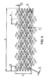
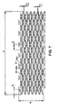
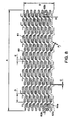
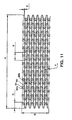
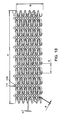
- Figs. 5-13 are flattened plan views showing stents made according to the present invention. Each of the stent patterns shown would be curved into a cylindrical shape as applied to the balloon catheter as shown in Fig. 1.
- the medical device 1 of the present invention includes a catheter 2 and a stent 3 mounted on the catheter 2 in an unexpanded condition.
- the stent 3 has a hollow, cylindrical body made with a plurality of rings. As shown, the stent 3 is crimped over a balloon 4 affixed to the catheter 2 near the distal end of the catheter 2.
- the stent 3 can include a variety of configurations as shown in Figs. 2 to 14 which are shown in an open and flattened configuration as they would appear in an unexpanded and uncrimped condition.
- the balloon 4 can be practically any balloon suitable for angioplasty procedures and capable of inflation to 810600 Nm -2 (8 atmospheres of pressure).
- a preferred type of balloon 4 is a balloon with multiple folds which permits the stent to expand evenly that is approximately the same length as the stent.
- the stent 3 can be held onto the balloon 4 by retention techniques that are well known to those skilled in the art.
- rings 10a-c are shown.
- Each of the rings 10a-c extend circumferentially around the cylindrical body of the stent 3 and include an undulating series of peaks 11 and valleys 12.
- the undulating peaks 11 and valleys 12 of the rings 10a-c are formed by opposing curved segments 13a-b joined to each other by substantially straight segments 14.
- the rings 10a-c are joined together in a repeating pattern by a series of links 15 which are shaped and arranged to promote longitudinal flexibility as the stent is delivered on the catheter and effective scaffolding after deployment.
- a link 15 can be provided which interconnects with the rings 10a-c at points 16a-b on the rings 10a-b which are substantially centered between the respective peaks 11 and valleys 12 of the rings 10a-c and yet allows the link to nest within the peaks 11 and valleys 12 of the rings 10a-c as the stent is crimped onto the balloon 4 of the catheter 3. This is accomplished in part by providing at least two curved segments 17a-b in the link in a central portion of the link 15. As shown in Fig.
- no more than one link 15 is connected to either of the points 16a-b.
- the nesting of link 15 and ring 10a-c components is also made possible by providing only three of the links 15 attaching each of the rings 10a-c to its immediate neighbor. This leaves some of the straight segments 14 without connections and the links are spaced-apart such that no links 15 have adjacent connections to the rings 10a-c which oppose each other.
- a radiopaque marker 18 is joined to ring 10a inside a circular land portion 19.
- a link 15a joins the land portion with the adjacent ring 10b such that the link 15a resides between two peaks of ring 10a such that it will not interfere with the ring as the stent 3 is crimped onto the balloon 4 of the catheter 2.
- the rings 20a-c are provided with inflection points 21 on some portions of the rings 20a-c which extend between an adjacent peak 22 and valley 23 of the rings 20a-c.
- a portion of the ring extends in a generally circumferential direction (indicated generally 24) for a short distance.
- the inflection point 21 is shown substantially centered between a peak 22 and a valley 23 of the rings 20a-c.
- a link 25 is joined at one end at the inflection point 21a on one ring 20a and also joined at a second end at a second inflection point 21b on an adjacent ring 20b. This link 25 joins the rings 20a-b together.
- Each link 25 includes at least two curved segments 26a-b in the unexpanded stent 3 which promote the tendency of the stent 3 to flex longitudinally when it is subjected to bending forces such as those encountered during delivery of the stent 3 and catheter 2 through a tortuous coronary artery. It can be seen in Fig. 3 that the short portion of the rings 20a-c at the inflection point 21 which extends generally circumferentially has a length measured circumferentially which is about equal to a width of the link 25 to which it is attached.
- the undulations of the rings 20a-c include generally straight segments 27 between the peaks 22 and valleys 23, the straight segments 27 are interrupted by an inflection point 21 which produces an offset portion in the straight segment 27 in a generally circumferential direction 24. Only one link 25 is shown to be connected to either of the inflection points 21a-b.
- the links 25 can be arranged to provide flexibility whether the peaks 22 and valleys 23 of the rings 20a-c are arranged to make the rings 20a-c appear to be mirror images to each other (i.e. peaks line up with or closely approach each other) or as shown here where the peaks 22 and valleys 23 are paired with each other in an in-phase relationship or any alignment of the rings intermediate to those positions.
- the rings 20a-c are joined by multiple links 25 (preferably 3 or more to provide good scaffolding) and are shown to have the same number of inflection points 21 on each ring 20a-c as the number of attaching links 25.
- any curves or bends in the links 25 are preferably of a complimentary shape to each other such that they will nest together when the stent 3 is crimped onto the balloon 4 of the catheter 2.
- the end ring 20a includes a radiopaque marker 28 which provides fluoroscopic confirmation of the position of the stent 3 when it is advanced into the patient.
- the adjacent ring portions are provided with curved segments 29a-b which permit them to nest with the circular form of the marker 28 as the stent 3 is crimped onto the balloon 4 of the catheter 2.
- the rings 30a-c of the stent 3 have undulating peaks 31 and valleys 32 arranged with the undulating peaks 31 and valleys 32 of an adjacent rings 30a-c such that the rings 30a-c appear as mirror images of each other.
- a link 33 can be provided which interconnects with the rings 30a-c at points on the rings which are substantially centered between the respective peaks 31 and valleys 32 of the rings 30a-c and yet allows the link 33 to nest within the peaks 31 and valleys 32 of the rings.
- a link 33 which includes a sharply curved segment 34a-b at each end and a straight or gently curved central segment provided that it is connected at a "dead end" where only one link 33 is connected at any one ring segment between a peak 31 and valley 32.
- a link 33 can also nest with the opposing ring segments as the stent 3 is crimped onto the balloon 4 of a catheter 2.
- Fig. 4 is the adjustment in the relative amplitudes of the undulations between the rings 30a-c. Ring 30a is shown to have a smaller amplitude in dimension "A" than the amplitude of ring 30b as shown in dimension "B".
- This variation in amplitude can be particularly important in stent designs where the stent 3 may tend to flare at the ends as the stent is advanced through tortuous arteries since the lower amplitude ring 30a at the end of the stent 3 will have a reduced tendency to be deformed and tip outward when the stent 3 is subjected to longitudinal bending forces.
- the lower amplitude ring 30a can be on a distal or proximal end of the stent 3. The person skilled in the art will appreciate that this can be especially important in situations where one advances the stent 3 and catheter 2 through a tortuous artery but, instead of deploying the stent 3, then wishes to withdraw the stent 3 into the guide catheter while it is still crimped on the balloon 4. If the end of the stent 3 has become flared during the failed deployment, it can catch on the distal edge of the guide catheter as it is being withdrawn.
- a full pattern of a stent 3 for a coronary artery application is shown which is substantially the same pattern which was discussed above in connection with Fig. 3.
- the stent 3 has a length "A" which can be about 8 to 30 mm (and as depicted could be about 15-25 mm) for a coronary artery application although those skilled in the art will appreciate that the pattern can be configured to give many lengths.
- the dimension "B” refers to the circumference of the stent 3 for a coronary application which can be about 3-7 mm and gives an uncrimped diameter for the stent 3 of about 1-2 mm.
- the dimension "C” refers to the width of one of the rings which in this example could be in the range of about .08 to .12 mm.
- the dimension “D” refers to the amplitude of one of the rings and in this example could be in the range of about .75 to 2.5 mm.
- the dimension “E” refers to the peak-to-peak spacing for the rings and in this example could be in the range of about 1-3 mm.
- the dimension “F” refers to the width of a connecting link and in this example could be in the range of about .06 to .1 mm.
- the dimensions G and H refer to the diameter of the radiopaque marker and the width of the portion of the ring holding the marker.
- This stent 3 can be made by laser cutting from a tube of stainless steel or other suitable material by methods which are well known by those skilled in the art. Similar structures are marked with the same dimensional symbols ("A" to "H") in each of the drawings Figs. 5-14 for the convenience of the reader.
- the stent 3 of Fig. 5 has been modified by the addition of more connecting links 40 and the use of shorter amplitude rings 41 (i.e. reductions in dimensions "D” and “E”) in combination with reductions in the widths in various components (i.e. reductions in dimensions "C” and “F”) in order to provide better crimp profile, flexibility and scaffolding.
- the links 40 can vary somewhat in width along their length in order to modify or direct the way in which the link 40 can flex as the stent 3 is deployed through a tortuous body lumen.
- the ends of the links 40 flare out just before the connection points 42a-b in order to provide increased resistance to flexing near the connection points 42a-b.
- the stent 3 is made in a configuration which combines features shown in the stents 3 of Figs. 3 and 4.
- the stent 3 employs rings 50 which are arranged in a mirror image configuration. Connecting links 51 are connected to rings 50 at inflection points 52a-b with a slightly curved connecting link 51 which provides improved flexibility.
- the connecting links 51 "dead end" at the inflection points 52a-b to also provide flexibility.
- the number of rings 50 are increased and the amplitude of the rings 50 is reduced (i.e. reductions in dimensions "D", "E”, "C” and “F”).
- the "cell” size i.e. the size of the smallest repeating unit in the pattern) is reduced and scaffolding is improved.
- the stent 3 of Fig. 6 is modified by adding a longer and more highly curved link 60 and by adding another two bends in the undulation in each of the rings 61.
- the resulting stent 3 had improved scaffolding from smaller cell size and more flexibility from the more curved link 60.
- Radiopaque markers 62a-b nest with the adjacent ring elements as the stent 3 is crimped onto the balloon 4 of the catheter 2.
- the links 60a-b connecting the ring immediately adjacent to the radiopaque markers are shorter than the other links and are attached to the ring at a portion of the ring away from the radiopaque marker 62a. This provides the markers 62a-b with additional space and ring flexibility to permit improved crimping of the stent 3 onto the balloon 4.
- the stent 3 is a maximum flexibility version of the stent 3 of Fig. 8 made by making the connecting link 70 even more curved and increasing the cell size to permit the link 70 to flex in the space between the peaks 71 and valleys 72 of adjacent rings 73.
- the stent 3 is a variant of the stent 3 of Fig. 6 in which the dimension "D" is relatively smaller in relation to dimension "E” such that more space is available between the rings 80 so that the stent 3 can flex with maximum clearance between those components when the stent 3 is deployed in the bend of a body lumen.
- Radiopaque markers 82a-b are located at opposite ends of the stent 3 to allow the physician to precisely identify the position of the ends of the stent 3 fluoroscopically while the stent 3 is being deployed into the patient.
- the markers 82a-b can take the form of a thin gold disk set into an portion of the pattern.
- the markers 82a-b have their highest fluoroscopic visibility when looking directly down onto the flat plane of the disk and lesser visibility when looking at the edge of the disk. Therefore, the markers 82a-b can be aligned with each other so as to both be visible at the same intensity no matter what the rotational orientation of the stent (as shown in Fig. 9) or offset (shown in Fig. 10 about 90 degrees offset) with regard to each other to permit at least one marker 82a-b to always be viewed in its highly observable flat orientation. More markers can be added to those shown in Figs. 9-10 so that each end of the stent 3 has two or more markers in a relative offset position which then permits one of the markers at each end to always be brightly observable no matter what rotational orientation the stent 3 is in.
- the stent 3 is a variant of the stent 3 of Figs. 3 and 4 with long, relatively straight links 90 joined with rings 91 at inflection points 92a-b. It should be noted that in the center of the pattern two links 90 are joined at each inflection point 92a-b on opposing sides without compromising the ability of the ring 91 and link 90 elements to nest as the stent 3 is crimped onto the balloon 4 of the catheter 2.
- the use of multiple links 90 at each inflection point 92a-b provides a greater number of links 90 overall and a therefore a greater amount of scaffolding in the expanded stent 3 than in other designs.
- the stent 3 is a variant of the stent 3 of Figs 3 and 12 with curved connecting links 100 replacing the straighter links in Fig. 12.
- the links 100 are connected to the rings 101 at inflection points 102a-b such that more than one link 100 is attached at each inflection point 102a-b.
- the stent 3 is a variant of the stent 3 of Fig. 12 in which a longer and more curved link 110 is used to improve flexibility of the stent 3.
- the links 110 include a peaked portion 111 which extends in the circumferential direction of the stent 3. It is important to note that the links 110 have peaked portions which have the ability to conform to each other and nest as the stent 3 is crimped onto the balloon 4 of the catheter 2.
- the stent 3 is a variant of the stent 3 of Fig. 13 in which the cell size is increased slightly and the shape of the peaked portion 120a-b of each link 121 are altered so that the adjacent peak portions 120a-b will conform and nest better when the stent 3 is crimped. It will be noted that every peak portion 120a-b is slightly offset from its nearest neighbor to compensate for the slight alteration in the shape of the link 121 that takes place as the stent 3 is crimped. This provides a more precise nesting of the links 121 in the crimped stent 3. Also to be noted in connection with Fig. 14 is the relative position of the connecting links 121, 122 with respect to the inflection point 123a.
- the first connecting link 121 is connected to the inflection point 123a at a lower portion of the inflection point 123a while the second connecting link 122 is connected at an opposite side of the inflection point 123a at an upper portion of the inflection point 123a.
- the connecting links 121, 122 are connected to adjacent rings 126a-b such that a link 121 connects at one end to one ring 126a at a lower portion of the inflection point 123a and at the other end at an upper portion of the inflection point 123b.
- each peak 124 and each valley 125 has two connecting links 121, 122 extending laterally past them to join with another ring 126a-b.
- the connecting links 121, 122 proceed from one end attachment at an inflection point 123a-b such that they parallel the portion of the ring 126a-b and are positioned such that when the stent 3 is expanded they will extend outward from the inflection point 123a-b and assist in the scaffolding provided by the central portion of the ring 126a-b.
- the connecting links 121, 122 also extend past the peak 124 or valley 125 components to extend the scaffolding provided by the peak 124 and valley 125 components of the rings 126a-b toward the next ring.
- connecting links 121, 122 extend upwardly past the peak 124 and valley 125 portions of the rings 126a-b into peaked portions 120a-b. This arrangement provides highly effective scaffolding for the stent 3 when it is expanded against a body lumen of the patient.
Landscapes
- Health & Medical Sciences (AREA)
- Engineering & Computer Science (AREA)
- Biomedical Technology (AREA)
- Heart & Thoracic Surgery (AREA)
- Life Sciences & Earth Sciences (AREA)
- Cardiology (AREA)
- Oral & Maxillofacial Surgery (AREA)
- Transplantation (AREA)
- Physics & Mathematics (AREA)
- Vascular Medicine (AREA)
- Optics & Photonics (AREA)
- Animal Behavior & Ethology (AREA)
- General Health & Medical Sciences (AREA)
- Public Health (AREA)
- Veterinary Medicine (AREA)
- Media Introduction/Drainage Providing Device (AREA)
- Materials For Medical Uses (AREA)
Applications Claiming Priority (2)
| Application Number | Priority Date | Filing Date | Title |
|---|---|---|---|
| US09/292,991 US6730116B1 (en) | 1999-04-16 | 1999-04-16 | Medical device for intraluminal endovascular stenting |
| EP00906944A EP1100408B1 (fr) | 1999-04-16 | 2000-01-18 | Instrument medical pour extenseur endovasculaire intraluminal |
Related Parent Applications (2)
| Application Number | Title | Priority Date | Filing Date |
|---|---|---|---|
| EP00906944.4 Division | 2000-01-18 | ||
| EP00906944A Division EP1100408B1 (fr) | 1999-04-16 | 2000-01-18 | Instrument medical pour extenseur endovasculaire intraluminal |
Publications (2)
| Publication Number | Publication Date |
|---|---|
| EP1891910A2 true EP1891910A2 (fr) | 2008-02-27 |
| EP1891910A3 EP1891910A3 (fr) | 2010-03-03 |
Family
ID=23127143
Family Applications (2)
| Application Number | Title | Priority Date | Filing Date |
|---|---|---|---|
| EP07016378A Withdrawn EP1891910A3 (fr) | 1999-04-16 | 2000-01-18 | Dispositif médical pour la pose d'endoprothèses endovasculaires intraluminales |
| EP00906944A Expired - Lifetime EP1100408B1 (fr) | 1999-04-16 | 2000-01-18 | Instrument medical pour extenseur endovasculaire intraluminal |
Family Applications After (1)
| Application Number | Title | Priority Date | Filing Date |
|---|---|---|---|
| EP00906944A Expired - Lifetime EP1100408B1 (fr) | 1999-04-16 | 2000-01-18 | Instrument medical pour extenseur endovasculaire intraluminal |
Country Status (6)
| Country | Link |
|---|---|
| US (2) | US6730116B1 (fr) |
| EP (2) | EP1891910A3 (fr) |
| JP (1) | JP3568899B2 (fr) |
| DE (1) | DE60037094T2 (fr) |
| IE (2) | IES20000078A2 (fr) |
| WO (1) | WO2000062710A1 (fr) |
Families Citing this family (237)
| Publication number | Priority date | Publication date | Assignee | Title |
|---|---|---|---|---|
| US7204848B1 (en) | 1995-03-01 | 2007-04-17 | Boston Scientific Scimed, Inc. | Longitudinally flexible expandable stent |
| US20040106985A1 (en) | 1996-04-26 | 2004-06-03 | Jang G. David | Intravascular stent |
| US6235053B1 (en) | 1998-02-02 | 2001-05-22 | G. David Jang | Tubular stent consists of chevron-shape expansion struts and contralaterally attached diagonal connectors |
| JP4636634B2 (ja) | 1996-04-26 | 2011-02-23 | ボストン サイエンティフィック サイムド,インコーポレイテッド | 脈管内ステント |
| US6241760B1 (en) | 1996-04-26 | 2001-06-05 | G. David Jang | Intravascular stent |
| EP0884029B1 (fr) | 1997-06-13 | 2004-12-22 | Gary J. Becker | Endoprothèse intraluminale extensible |
| US7208011B2 (en) | 2001-08-20 | 2007-04-24 | Conor Medsystems, Inc. | Implantable medical device with drug filled holes |
| US20040254635A1 (en) | 1998-03-30 | 2004-12-16 | Shanley John F. | Expandable medical device for delivery of beneficial agent |
| US7179289B2 (en) * | 1998-03-30 | 2007-02-20 | Conor Medsystems, Inc. | Expandable medical device for delivery of beneficial agent |
| US7208010B2 (en) * | 2000-10-16 | 2007-04-24 | Conor Medsystems, Inc. | Expandable medical device for delivery of beneficial agent |
| US6241762B1 (en) | 1998-03-30 | 2001-06-05 | Conor Medsystems, Inc. | Expandable medical device with ductile hinges |
| US6261319B1 (en) | 1998-07-08 | 2001-07-17 | Scimed Life Systems, Inc. | Stent |
| US6755856B2 (en) | 1998-09-05 | 2004-06-29 | Abbott Laboratories Vascular Enterprises Limited | Methods and apparatus for stenting comprising enhanced embolic protection, coupled with improved protection against restenosis and thrombus formation |
| US6190403B1 (en) | 1998-11-13 | 2001-02-20 | Cordis Corporation | Low profile radiopaque stent with increased longitudinal flexibility and radial rigidity |
| US20010047200A1 (en) * | 1999-10-13 | 2001-11-29 | Raymond Sun | Non-foreshortening intraluminal prosthesis |
| EP1132058A1 (fr) | 2000-03-06 | 2001-09-12 | Advanced Laser Applications Holding S.A. | Prothèse intravasculaire |
| DE10044043A1 (de) * | 2000-08-30 | 2002-03-14 | Biotronik Mess & Therapieg | Reponierbarer Stent |
| DE60122536T2 (de) * | 2000-09-22 | 2006-12-14 | Boston Scientific Scimed, Inc., Maple Grove | Intravasculärer stent |
| US7766956B2 (en) | 2000-09-22 | 2010-08-03 | Boston Scientific Scimed, Inc. | Intravascular stent and assembly |
| AU2001296297A1 (en) * | 2000-09-23 | 2002-04-02 | G. David Jang | Intravascular stent |
| US6485508B1 (en) | 2000-10-13 | 2002-11-26 | Mcguinness Colm P. | Low profile stent |
| PT1328213E (pt) | 2000-10-16 | 2005-10-31 | Conor Medsystems Inc | Dispositivo medico expansivel para a administracao de um agente benefico |
| US6929660B1 (en) | 2000-12-22 | 2005-08-16 | Advanced Cardiovascular Systems, Inc. | Intravascular stent |
| JP4768172B2 (ja) * | 2001-09-19 | 2011-09-07 | 株式会社カネカ | ステント |
| EP1364676A4 (fr) * | 2001-02-01 | 2007-10-31 | Kaneka Corp | Endoprothese |
| US20040204756A1 (en) * | 2004-02-11 | 2004-10-14 | Diaz Stephen Hunter | Absorbent article with improved liquid acquisition capacity |
| US20040073294A1 (en) | 2002-09-20 | 2004-04-15 | Conor Medsystems, Inc. | Method and apparatus for loading a beneficial agent into an expandable medical device |
| US20040220660A1 (en) * | 2001-02-05 | 2004-11-04 | Shanley John F. | Bioresorbable stent with beneficial agent reservoirs |
| US6790227B2 (en) | 2001-03-01 | 2004-09-14 | Cordis Corporation | Flexible stent |
| US6998060B2 (en) | 2001-03-01 | 2006-02-14 | Cordis Corporation | Flexible stent and method of manufacture |
| US6955686B2 (en) | 2001-03-01 | 2005-10-18 | Cordis Corporation | Flexible stent |
| AU784552B2 (en) | 2001-03-02 | 2006-05-04 | Cardinal Health 529, Llc | Flexible stent |
| DE10118944B4 (de) * | 2001-04-18 | 2013-01-31 | Merit Medical Systems, Inc. | Entfernbare, im wesentlichen zylindrische Implantate |
| US6629994B2 (en) | 2001-06-11 | 2003-10-07 | Advanced Cardiovascular Systems, Inc. | Intravascular stent |
| CA2454871C (fr) | 2001-07-26 | 2008-09-30 | Alveolus Inc | Endoprothese amovible et procede d'utilisation associe |
| US7842083B2 (en) | 2001-08-20 | 2010-11-30 | Innovational Holdings, Llc. | Expandable medical device with improved spatial distribution |
| US7056338B2 (en) | 2003-03-28 | 2006-06-06 | Conor Medsystems, Inc. | Therapeutic agent delivery device with controlled therapeutic agent release rates |
| US20040249443A1 (en) * | 2001-08-20 | 2004-12-09 | Shanley John F. | Expandable medical device for treating cardiac arrhythmias |
| GB0121980D0 (en) | 2001-09-11 | 2001-10-31 | Cathnet Science Holding As | Expandable stent |
| IES20010828A2 (en) * | 2001-09-12 | 2003-03-19 | Medtronic Inc | Medical device for intraluminal endovascular stenting |
| EP1516600B1 (fr) * | 2001-09-18 | 2007-03-14 | Abbott Laboratories Vascular Enterprises Limited | Stent |
| US7182779B2 (en) | 2001-12-03 | 2007-02-27 | Xtent, Inc. | Apparatus and methods for positioning prostheses for deployment from a catheter |
| US7351255B2 (en) | 2001-12-03 | 2008-04-01 | Xtent, Inc. | Stent delivery apparatus and method |
| US7892273B2 (en) | 2001-12-03 | 2011-02-22 | Xtent, Inc. | Custom length stent apparatus |
| US20030135266A1 (en) | 2001-12-03 | 2003-07-17 | Xtent, Inc. | Apparatus and methods for delivery of multiple distributed stents |
| US8080048B2 (en) * | 2001-12-03 | 2011-12-20 | Xtent, Inc. | Stent delivery for bifurcated vessels |
| US7294146B2 (en) | 2001-12-03 | 2007-11-13 | Xtent, Inc. | Apparatus and methods for delivery of variable length stents |
| US7147656B2 (en) | 2001-12-03 | 2006-12-12 | Xtent, Inc. | Apparatus and methods for delivery of braided prostheses |
| US7309350B2 (en) | 2001-12-03 | 2007-12-18 | Xtent, Inc. | Apparatus and methods for deployment of vascular prostheses |
| US20040186551A1 (en) | 2003-01-17 | 2004-09-23 | Xtent, Inc. | Multiple independent nested stent structures and methods for their preparation and deployment |
| US7137993B2 (en) | 2001-12-03 | 2006-11-21 | Xtent, Inc. | Apparatus and methods for delivery of multiple distributed stents |
| US20030225448A1 (en) * | 2002-05-28 | 2003-12-04 | Scimed Life Systems, Inc. | Polar radiopaque marker for stent |
| US20040006380A1 (en) * | 2002-07-05 | 2004-01-08 | Buck Jerrick C. | Stent delivery system |
| US9561123B2 (en) | 2002-08-30 | 2017-02-07 | C.R. Bard, Inc. | Highly flexible stent and method of manufacture |
| US6878162B2 (en) | 2002-08-30 | 2005-04-12 | Edwards Lifesciences Ag | Helical stent having improved flexibility and expandability |
| US7758636B2 (en) * | 2002-09-20 | 2010-07-20 | Innovational Holdings Llc | Expandable medical device with openings for delivery of multiple beneficial agents |
| WO2004026174A2 (fr) * | 2002-09-20 | 2004-04-01 | Conor Medsystems, Inc. | Dispositif medical extensible pourvu d'ouvertures pour l'administration d'agents benefiques multiples |
| US20040093056A1 (en) | 2002-10-26 | 2004-05-13 | Johnson Lianw M. | Medical appliance delivery apparatus and method of use |
| US7527644B2 (en) | 2002-11-05 | 2009-05-05 | Alveolus Inc. | Stent with geometry determinated functionality and method of making the same |
| US7637942B2 (en) | 2002-11-05 | 2009-12-29 | Merit Medical Systems, Inc. | Coated stent with geometry determinated functionality and method of making the same |
| US7959671B2 (en) | 2002-11-05 | 2011-06-14 | Merit Medical Systems, Inc. | Differential covering and coating methods |
| US7875068B2 (en) | 2002-11-05 | 2011-01-25 | Merit Medical Systems, Inc. | Removable biliary stent |
| US20040142014A1 (en) * | 2002-11-08 | 2004-07-22 | Conor Medsystems, Inc. | Method and apparatus for reducing tissue damage after ischemic injury |
| AU2003285195A1 (en) * | 2002-11-08 | 2004-06-03 | Innovational Holdings, Llc | Method and apparatus for treating vulnerable artherosclerotic plaque |
| DE10261822A1 (de) * | 2002-12-20 | 2004-07-01 | Biotronik Meß- und Therapiegeräte GmbH & Co. Ingenieurbüro Berlin | Helix-Steg-Verbindung |
| AU2004224415B2 (en) * | 2003-03-19 | 2011-07-14 | Vactronix Scientific, Llc | Endoluminal stent having mid-interconnecting members |
| US20050010170A1 (en) * | 2004-02-11 | 2005-01-13 | Shanley John F | Implantable medical device with beneficial agent concentration gradient |
| AU2004226327A1 (en) | 2003-03-28 | 2004-10-14 | Innovational Holdings, Llc | Implantable medical device with beneficial agent concentration gradient |
| US7637934B2 (en) | 2003-03-31 | 2009-12-29 | Merit Medical Systems, Inc. | Medical appliance optical delivery and deployment apparatus and method |
| US7604660B2 (en) | 2003-05-01 | 2009-10-20 | Merit Medical Systems, Inc. | Bifurcated medical appliance delivery apparatus and method |
| JPWO2004108201A1 (ja) * | 2003-06-02 | 2006-07-20 | ニプロ株式会社 | 血管追従性のよい柔軟なステント |
| US7169179B2 (en) * | 2003-06-05 | 2007-01-30 | Conor Medsystems, Inc. | Drug delivery device and method for bi-directional drug delivery |
| US7241308B2 (en) | 2003-06-09 | 2007-07-10 | Xtent, Inc. | Stent deployment systems and methods |
| US7785653B2 (en) * | 2003-09-22 | 2010-08-31 | Innovational Holdings Llc | Method and apparatus for loading a beneficial agent into an expandable medical device |
| US7326236B2 (en) | 2003-12-23 | 2008-02-05 | Xtent, Inc. | Devices and methods for controlling and indicating the length of an interventional element |
| EP1997456B1 (fr) * | 2004-02-13 | 2011-12-07 | Innovational Holdings, LLC | Dispositif et méthode pour revêtement médical de fil |
| JP4542360B2 (ja) * | 2004-03-30 | 2010-09-15 | テルモ株式会社 | 自己拡張型生体内留置用ステント |
| US7323006B2 (en) | 2004-03-30 | 2008-01-29 | Xtent, Inc. | Rapid exchange interventional devices and methods |
| US20050287287A1 (en) * | 2004-06-24 | 2005-12-29 | Parker Theodore L | Methods and systems for loading an implantable medical device with beneficial agent |
| US8317859B2 (en) | 2004-06-28 | 2012-11-27 | J.W. Medical Systems Ltd. | Devices and methods for controlling expandable prostheses during deployment |
| US20050288766A1 (en) | 2004-06-28 | 2005-12-29 | Xtent, Inc. | Devices and methods for controlling expandable prostheses during deployment |
| USD516723S1 (en) | 2004-07-06 | 2006-03-07 | Conor Medsystems, Inc. | Stent wall structure |
| US20060064155A1 (en) * | 2004-09-01 | 2006-03-23 | Pst, Llc | Stent and method for manufacturing the stent |
| US20060074480A1 (en) * | 2004-09-01 | 2006-04-06 | Pst, Llc | Stent and method for manufacturing the stent |
| GB0419954D0 (en) | 2004-09-08 | 2004-10-13 | Advotek Medical Devices Ltd | System for directing therapy |
| US7887579B2 (en) * | 2004-09-29 | 2011-02-15 | Merit Medical Systems, Inc. | Active stent |
| DE102005013547B4 (de) * | 2005-03-23 | 2009-02-05 | Admedes Schuessler Gmbh | Aneurysmen-Stent und Verfahren zu seiner Herstellung |
| CN102309370B (zh) | 2005-04-04 | 2015-04-15 | 灵活支架解决方案股份有限公司 | 可挠支架 |
| DE102005019612B4 (de) * | 2005-04-27 | 2010-11-25 | Admedes Schuessler Gmbh | Mechanische Verriegelung eines Röntgenmarkers im Eyelet eines Stents oder in einem anderen Körperimplantat |
| US7731654B2 (en) | 2005-05-13 | 2010-06-08 | Merit Medical Systems, Inc. | Delivery device with viewing window and associated method |
| US7476245B2 (en) * | 2005-08-16 | 2009-01-13 | Advanced Cardiovascular Systems, Inc. | Polymeric stent patterns |
| DE102005039136B4 (de) * | 2005-08-18 | 2011-07-28 | Admedes Schuessler GmbH, 75179 | Verbesserung der Röntgensichtbarkeit und Korrosionsbeständigkeit von NiTi Stents unter Einsatz von Nieten aus Sandwichmaterial |
| US7404823B2 (en) * | 2005-10-31 | 2008-07-29 | Boston Scientific Scimed, Inc. | Stent configurations |
| US7381217B2 (en) * | 2005-12-23 | 2008-06-03 | Boston Scientific Scimed, Inc. | Serpentine stent pattern |
| US20070156230A1 (en) | 2006-01-04 | 2007-07-05 | Dugan Stephen R | Stents with radiopaque markers |
| US20070162110A1 (en) * | 2006-01-06 | 2007-07-12 | Vipul Bhupendra Dave | Bioabsorbable drug delivery devices |
| US20070158880A1 (en) * | 2006-01-06 | 2007-07-12 | Vipul Bhupendra Dave | Methods of making bioabsorbable drug delivery devices comprised of solvent cast tubes |
| US20070160672A1 (en) * | 2006-01-06 | 2007-07-12 | Vipul Bhupendra Dave | Methods of making bioabsorbable drug delivery devices comprised of solvent cast films |
| JP2007195807A (ja) * | 2006-01-27 | 2007-08-09 | Juki Corp | 差動送りミシン |
| US9456911B2 (en) | 2006-02-14 | 2016-10-04 | Angiomed Gmbh & Co. Medizintechnik | Highly flexible stent and method of manufacture |
| AU2007227000A1 (en) | 2006-03-20 | 2007-09-27 | Xtent, Inc. | Apparatus and methods for deployment of linked prosthetic segments |
| US8043358B2 (en) * | 2006-03-29 | 2011-10-25 | Boston Scientific Scimed, Inc. | Stent with overlap and high extension |
| US8348991B2 (en) * | 2006-03-29 | 2013-01-08 | Boston Scientific Scimed, Inc. | Stent with overlap and high expansion |
| US7318837B2 (en) * | 2006-03-30 | 2008-01-15 | Medtronic Vascular, Inc. | Customized alloys for stents |
| US20130190676A1 (en) | 2006-04-20 | 2013-07-25 | Limflow Gmbh | Devices and methods for fluid flow through body passages |
| US7955383B2 (en) * | 2006-04-25 | 2011-06-07 | Medtronics Vascular, Inc. | Laminated implantable medical device having a metallic coating |
| US7691400B2 (en) | 2006-05-05 | 2010-04-06 | Medtronic Vascular, Inc. | Medical device having coating with zeolite drug reservoirs |
| EP2023869B1 (fr) * | 2006-05-12 | 2019-09-18 | Cardinal Health Switzerland 515 GmbH | Endoprothèse flexible à élution de médicament bioabsorbable et expansible par ballonnet |
| US20130331926A1 (en) | 2006-05-26 | 2013-12-12 | Abbott Cardiovascular Systems Inc. | Stents With Radiopaque Markers |
| US20070283969A1 (en) * | 2006-06-12 | 2007-12-13 | Medtronic Vascular, Inc. | Method of Diagnosing and Treating Erectile Dysfunction |
| US8029558B2 (en) * | 2006-07-07 | 2011-10-04 | Abbott Cardiovascular Systems, Inc. | Stent and catheter assembly and method for treating bifurcations |
| US20080015684A1 (en) | 2006-07-11 | 2008-01-17 | Wu Patrick P | Method And Apparatus For Attaching Radiopaque Markers To A Stent |
| WO2008024574A1 (fr) | 2006-07-20 | 2008-02-28 | Orbusneich Medical, Inc. | Dispositif médical polymère bioabsorbable |
| EP3061791B1 (fr) | 2006-07-20 | 2019-01-16 | OrbusNeich Medical, Inc. | Composition polymère bioabsorbable pour un dispositif médical |
| US7833260B2 (en) * | 2006-07-20 | 2010-11-16 | Orbusneich Medical, Inc. | Bioabsorbable polymeric medical device |
| DE07841109T1 (de) * | 2006-08-22 | 2010-02-11 | Abbott Cardiovascular Systems Inc., Santa Clara | Intravaskulärer stent |
| US8882826B2 (en) | 2006-08-22 | 2014-11-11 | Abbott Cardiovascular Systems Inc. | Intravascular stent |
| US8834554B2 (en) * | 2006-08-22 | 2014-09-16 | Abbott Cardiovascular Systems Inc. | Intravascular stent |
| US8414637B2 (en) * | 2006-09-08 | 2013-04-09 | Boston Scientific Scimed, Inc. | Stent |
| US7988720B2 (en) | 2006-09-12 | 2011-08-02 | Boston Scientific Scimed, Inc. | Longitudinally flexible expandable stent |
| US7959942B2 (en) * | 2006-10-20 | 2011-06-14 | Orbusneich Medical, Inc. | Bioabsorbable medical device with coating |
| EP2073754A4 (fr) * | 2006-10-20 | 2012-09-26 | Orbusneich Medical Inc | Composition polymère bioabsorbable et fond de dispositif médical |
| US20080119927A1 (en) * | 2006-11-17 | 2008-05-22 | Medtronic Vascular, Inc. | Stent Coating Including Therapeutic Biodegradable Glass, and Method of Making |
| US20080133000A1 (en) * | 2006-12-01 | 2008-06-05 | Medtronic Vascular, Inc. | Bifurcated Stent With Variable Length Branches |
| US7651527B2 (en) | 2006-12-15 | 2010-01-26 | Medtronic Vascular, Inc. | Bioresorbable stent |
| WO2008096512A1 (fr) * | 2007-02-09 | 2008-08-14 | Piolax Medical Devices, Inc. | Stent |
| US8333799B2 (en) | 2007-02-12 | 2012-12-18 | C. R. Bard, Inc. | Highly flexible stent and method of manufacture |
| EP2120785B1 (fr) * | 2007-02-12 | 2021-12-01 | C.R. Bard, Inc. | Endoprothèse très flexible et procédé de fabrication |
| US20080199510A1 (en) | 2007-02-20 | 2008-08-21 | Xtent, Inc. | Thermo-mechanically controlled implants and methods of use |
| US20080208352A1 (en) * | 2007-02-27 | 2008-08-28 | Medtronic Vascular, Inc. | Stent Having Controlled Porosity for Improved Ductility |
| US20080206441A1 (en) * | 2007-02-27 | 2008-08-28 | Medtronic Vascular, Inc. | Ion Beam Etching a Surface of an Implantable Medical Device |
| US8974514B2 (en) | 2007-03-13 | 2015-03-10 | Abbott Cardiovascular Systems Inc. | Intravascular stent with integrated link and ring strut |
| US20080234800A1 (en) * | 2007-03-20 | 2008-09-25 | Medtronic Vascular, Inc. | Stent Including a Toggle Lock |
| US8486132B2 (en) | 2007-03-22 | 2013-07-16 | J.W. Medical Systems Ltd. | Devices and methods for controlling expandable prostheses during deployment |
| US8545548B2 (en) * | 2007-03-30 | 2013-10-01 | DePuy Synthes Products, LLC | Radiopaque markers for implantable stents and methods for manufacturing the same |
| US20080249458A1 (en) * | 2007-04-09 | 2008-10-09 | Medtronic Vascular, Inc. | Intraventricular Shunt and Methods of Use Therefor |
| US8128679B2 (en) | 2007-05-23 | 2012-03-06 | Abbott Laboratories Vascular Enterprises Limited | Flexible stent with torque-absorbing connectors |
| DE102007030753A1 (de) * | 2007-07-02 | 2009-01-08 | Acandis Gmbh & Co. Kg | Stent |
| US20110130822A1 (en) * | 2007-07-20 | 2011-06-02 | Orbusneich Medical, Inc. | Bioabsorbable Polymeric Compositions and Medical Devices |
| US7988723B2 (en) | 2007-08-02 | 2011-08-02 | Flexible Stenting Solutions, Inc. | Flexible stent |
| US7896911B2 (en) | 2007-12-12 | 2011-03-01 | Innovasc Llc | Device and method for tacking plaque to blood vessel wall |
| US8128677B2 (en) | 2007-12-12 | 2012-03-06 | Intact Vascular LLC | Device and method for tacking plaque to a blood vessel wall |
| US9375327B2 (en) | 2007-12-12 | 2016-06-28 | Intact Vascular, Inc. | Endovascular implant |
| US10022250B2 (en) | 2007-12-12 | 2018-07-17 | Intact Vascular, Inc. | Deployment device for placement of multiple intraluminal surgical staples |
| US10166127B2 (en) | 2007-12-12 | 2019-01-01 | Intact Vascular, Inc. | Endoluminal device and method |
| US9603730B2 (en) | 2007-12-12 | 2017-03-28 | Intact Vascular, Inc. | Endoluminal device and method |
| US7972373B2 (en) * | 2007-12-19 | 2011-07-05 | Advanced Technologies And Regenerative Medicine, Llc | Balloon expandable bioabsorbable stent with a single stress concentration region interconnecting adjacent struts |
| US9101503B2 (en) | 2008-03-06 | 2015-08-11 | J.W. Medical Systems Ltd. | Apparatus having variable strut length and methods of use |
| US20090248034A1 (en) * | 2008-03-28 | 2009-10-01 | Medtronic Vascular, Inc. | Method of Diagnosing and Treating Benign Prostatic Hyperplasia |
| FR2930889B1 (fr) * | 2008-05-12 | 2011-12-16 | Hexacath | Dispositif medical implantable avec a son extremite proximale, un moyen de positionnement a un endroit precis d'embranchement d'un vaisseau sanguin tel qu'une coronaire |
| US8147898B2 (en) * | 2008-07-25 | 2012-04-03 | Medtronic Vascular, Inc. | Low temperature drug deposition |
| US20100036471A1 (en) * | 2008-08-05 | 2010-02-11 | Medtronic Vascular, Inc. | Method of Diagnosing and Treating Lower Urinary Tract Symptoms |
| US8808347B2 (en) | 2008-09-25 | 2014-08-19 | Advanced Bifurcation Systems, Inc. | Stent alignment during treatment of a bifurcation |
| AU2009296415B2 (en) | 2008-09-25 | 2015-11-19 | Advanced Bifurcation Systems Inc. | Partially crimped stent |
| US12076258B2 (en) | 2008-09-25 | 2024-09-03 | Advanced Bifurcation Systems Inc. | Selective stent crimping |
| US11298252B2 (en) | 2008-09-25 | 2022-04-12 | Advanced Bifurcation Systems Inc. | Stent alignment during treatment of a bifurcation |
| US8821562B2 (en) | 2008-09-25 | 2014-09-02 | Advanced Bifurcation Systems, Inc. | Partially crimped stent |
| US8769796B2 (en) | 2008-09-25 | 2014-07-08 | Advanced Bifurcation Systems, Inc. | Selective stent crimping |
| US12324756B2 (en) | 2008-09-25 | 2025-06-10 | Advanced Bifurcation Systems Inc. | System and methods for treating a bifurcation |
| US9149376B2 (en) | 2008-10-06 | 2015-10-06 | Cordis Corporation | Reconstrainable stent delivery system |
| EP2349125B1 (fr) * | 2008-10-10 | 2017-04-05 | OrbusNeich Medical, Inc. | Dispositif médical en polymère bioabsorbable |
| EP2349077A4 (fr) * | 2008-10-11 | 2015-01-21 | Orbusneich Medical Inc | Compositions polymères bioabsorbables et dispositifs médicaux |
| US20100204770A1 (en) * | 2009-02-10 | 2010-08-12 | Medtronic Vascular, Inc. | Stent Delivery System Permitting in Vivo Stent Repositioning |
| US8021420B2 (en) * | 2009-03-12 | 2011-09-20 | Medtronic Vascular, Inc. | Prosthetic valve delivery system |
| US8052741B2 (en) * | 2009-03-23 | 2011-11-08 | Medtronic Vascular, Inc. | Branch vessel prosthesis with a roll-up sealing assembly |
| US20100256723A1 (en) * | 2009-04-03 | 2010-10-07 | Medtronic Vascular, Inc. | Prosthetic Valve With Device for Restricting Expansion |
| US7967138B2 (en) | 2009-04-06 | 2011-06-28 | Medtronic Vascular, Inc. | Packaging systems for percutaneously deliverable bioprosthetic valves |
| US20100261737A1 (en) * | 2009-04-10 | 2010-10-14 | Medtronic Vascular, Inc. | Method of Treating Erectile Dysfunction |
| US20100268320A1 (en) | 2009-04-17 | 2010-10-21 | Medtronic Vascular, Inc. | Endovascular Implant Having an Integral Graft Component and Method of Manufacture |
| US8052737B2 (en) * | 2009-05-05 | 2011-11-08 | Medtronic Vascular, Inc. | Implantable temporary flow restrictor device |
| US8298279B2 (en) * | 2009-09-24 | 2012-10-30 | Medtronic Vascular, Inc. | Stent including a toggle lock strut |
| US8114149B2 (en) * | 2009-10-20 | 2012-02-14 | Svelte Medical Systems, Inc. | Hybrid stent with helical connectors |
| US20110098799A1 (en) * | 2009-10-27 | 2011-04-28 | Medtronic Vascular, Inc. | Stent Combined with a Biological Scaffold Seeded With Endothelial Cells |
| US8808353B2 (en) | 2010-01-30 | 2014-08-19 | Abbott Cardiovascular Systems Inc. | Crush recoverable polymer scaffolds having a low crossing profile |
| US8568471B2 (en) | 2010-01-30 | 2013-10-29 | Abbott Cardiovascular Systems Inc. | Crush recoverable polymer scaffolds |
| EP2549952A4 (fr) | 2010-03-24 | 2017-01-04 | Advanced Bifurcation Systems, Inc. | Système et procédé pour traiter une bifurcation |
| CA2794064A1 (fr) | 2010-03-24 | 2011-09-29 | Advanced Bifurcation Systems, Inc. | Procedes et systemes pour le traitement d'une bifurcation avec une implantation d'endoprothese vasculaire provisoire de ramification laterale |
| JP2013529507A (ja) | 2010-06-21 | 2013-07-22 | ゾリオン メディカル インコーポレイテッド | 生体吸収性インプラント |
| AU2011285808B2 (en) * | 2010-08-02 | 2015-04-30 | Cardinal Health 529, Llc | Flexible helical stent having intermediated non-helical region |
| CA2807119C (fr) * | 2010-08-02 | 2017-08-01 | Cordis Corporation | Endoprothese helicoidale flexible comprenant differentes regions helicoidales |
| US8986369B2 (en) | 2010-12-01 | 2015-03-24 | Zorion Medical, Inc. | Magnesium-based absorbable implants |
| EP2658484A1 (fr) * | 2010-12-30 | 2013-11-06 | Boston Scientific Scimed, Inc. | Modèles d'endoprothèses déployables en plusieurs étapes |
| EP2672932B1 (fr) | 2011-02-08 | 2018-09-19 | Advanced Bifurcation Systems, Inc. | Système pour traiter une bifurcation à l'aide d'une endoprothèse totalement sertie |
| EP2672925B1 (fr) | 2011-02-08 | 2017-05-03 | Advanced Bifurcation Systems, Inc. | Appareil comprenant lusieurs endoprothèses et plusieurs ballonnets pour traiter des bifurcations |
| US8790388B2 (en) | 2011-03-03 | 2014-07-29 | Boston Scientific Scimed, Inc. | Stent with reduced profile |
| US20140213971A1 (en) | 2011-04-27 | 2014-07-31 | Mark J. Dolan | Nerve impingement systems including an intravascular prosthesis and an extravascular prosthesis and associated systems and methods |
| US9198706B2 (en) * | 2011-05-12 | 2015-12-01 | Cvdevices, Llc | Systems and methods for cryoblation of a tissue |
| US10285831B2 (en) | 2011-06-03 | 2019-05-14 | Intact Vascular, Inc. | Endovascular implant |
| US8726483B2 (en) | 2011-07-29 | 2014-05-20 | Abbott Cardiovascular Systems Inc. | Methods for uniform crimping and deployment of a polymer scaffold |
| CN107157632B (zh) | 2012-01-25 | 2021-05-25 | 因特脉管有限公司 | 腔内装置和方法 |
| JP2013192886A (ja) * | 2012-03-22 | 2013-09-30 | Terumo Corp | ステント |
| AU2013263411B2 (en) | 2012-05-14 | 2017-05-25 | C.R. Bard, Inc. | Uniformly expandable stent |
| US9233015B2 (en) | 2012-06-15 | 2016-01-12 | Trivascular, Inc. | Endovascular delivery system with an improved radiopaque marker scheme |
| US10835367B2 (en) | 2013-03-08 | 2020-11-17 | Limflow Gmbh | Devices for fluid flow through body passages |
| EP4427712A3 (fr) | 2013-03-08 | 2024-11-13 | LimFlow GmbH | Procédés et systèmes pour fournir ou maintenir un écoulement de fluide à travers des passages corporels |
| USD723165S1 (en) | 2013-03-12 | 2015-02-24 | C. R. Bard, Inc. | Stent |
| US10561509B2 (en) | 2013-03-13 | 2020-02-18 | DePuy Synthes Products, Inc. | Braided stent with expansion ring and method of delivery |
| US10271975B2 (en) * | 2013-03-15 | 2019-04-30 | Atrium Medical Corporation | Stent device having reduced foreshortening and recoil and method of making same |
| US10085859B2 (en) | 2013-07-03 | 2018-10-02 | Medtronic Vascular, Inc. | Methods of manufacturing a drug-eluting stent |
| WO2015007435A1 (fr) * | 2013-07-19 | 2015-01-22 | Biotronik Ag | Endoprothèse |
| JP6081948B2 (ja) * | 2014-03-25 | 2017-02-15 | 株式会社World Medish Technology | 柔軟性ステント |
| US10206796B2 (en) | 2014-08-27 | 2019-02-19 | DePuy Synthes Products, Inc. | Multi-strand implant with enhanced radiopacity |
| US10722389B2 (en) | 2015-01-07 | 2020-07-28 | Sahajanand Medical Technologies Private Limited | Endoluminal stent |
| US9375336B1 (en) | 2015-01-29 | 2016-06-28 | Intact Vascular, Inc. | Delivery device and method of delivery |
| US9433520B2 (en) | 2015-01-29 | 2016-09-06 | Intact Vascular, Inc. | Delivery device and method of delivery |
| US9999527B2 (en) | 2015-02-11 | 2018-06-19 | Abbott Cardiovascular Systems Inc. | Scaffolds having radiopaque markers |
| US9737368B2 (en) | 2015-02-24 | 2017-08-22 | Abbott Cardiovascular Systems Inc. | System and method for attaching a radiopaque marker bead to an endoprosthesis |
| US9700443B2 (en) | 2015-06-12 | 2017-07-11 | Abbott Cardiovascular Systems Inc. | Methods for attaching a radiopaque marker to a scaffold |
| US10993824B2 (en) | 2016-01-01 | 2021-05-04 | Intact Vascular, Inc. | Delivery device and method of delivery |
| CA3018182A1 (fr) | 2016-03-31 | 2017-10-05 | Vesper Medical, Inc. | Implants intravasculaires |
| US10758384B2 (en) | 2016-07-13 | 2020-09-01 | Cook Medical Technologies Llc | Stent having reduced foreshortening |
| US10076428B2 (en) | 2016-08-25 | 2018-09-18 | DePuy Synthes Products, Inc. | Expansion ring for a braided stent |
| US10292851B2 (en) | 2016-09-30 | 2019-05-21 | DePuy Synthes Products, Inc. | Self-expanding device delivery apparatus with dual function bump |
| EP3609415B1 (fr) | 2017-04-10 | 2023-08-23 | LimFlow GmbH | Dispositifs de traitement du système vasculaire des extrémités inférieures |
| US10463514B2 (en) * | 2017-06-27 | 2019-11-05 | Abbott Cardiovascular Systems Inc. | Intravascular stent having high fatigue performance |
| US10238513B2 (en) | 2017-07-19 | 2019-03-26 | Abbott Cardiovascular Systems Inc. | Intravascular stent |
| US11660218B2 (en) | 2017-07-26 | 2023-05-30 | Intact Vascular, Inc. | Delivery device and method of delivery |
| US10849769B2 (en) | 2017-08-23 | 2020-12-01 | Vesper Medical, Inc. | Non-foreshortening stent |
| US11628076B2 (en) | 2017-09-08 | 2023-04-18 | Vesper Medical, Inc. | Hybrid stent |
| US10271977B2 (en) | 2017-09-08 | 2019-04-30 | Vesper Medical, Inc. | Hybrid stent |
| US11357650B2 (en) | 2019-02-28 | 2022-06-14 | Vesper Medical, Inc. | Hybrid stent |
| US11364134B2 (en) | 2018-02-15 | 2022-06-21 | Vesper Medical, Inc. | Tapering stent |
| US10500078B2 (en) | 2018-03-09 | 2019-12-10 | Vesper Medical, Inc. | Implantable stent |
| CA3094521A1 (fr) * | 2018-03-29 | 2019-10-03 | Sahajanand Medical Technologies Private Limited | Stent |
| US10441449B1 (en) | 2018-05-30 | 2019-10-15 | Vesper Medical, Inc. | Rotary handle stent delivery system and method |
| AU2019204522A1 (en) | 2018-07-30 | 2020-02-13 | DePuy Synthes Products, Inc. | Systems and methods of manufacturing and using an expansion ring |
| US10278848B1 (en) | 2018-08-06 | 2019-05-07 | DePuy Synthes Products, Inc. | Stent delivery with expansion assisting delivery wire |
| US10456280B1 (en) | 2018-08-06 | 2019-10-29 | DePuy Synthes Products, Inc. | Systems and methods of using a braided implant |
| US10449073B1 (en) | 2018-09-18 | 2019-10-22 | Vesper Medical, Inc. | Rotary handle stent delivery system and method |
| CN112955207A (zh) | 2018-10-09 | 2021-06-11 | 林弗洛公司 | 用于导管对准的设备和方法 |
| US11039944B2 (en) | 2018-12-27 | 2021-06-22 | DePuy Synthes Products, Inc. | Braided stent system with one or more expansion rings |
| US11517457B2 (en) | 2019-07-03 | 2022-12-06 | Abbott Cardiovascular Systems Inc. | Intravascular stent |
| AU2020373046A1 (en) | 2019-11-01 | 2022-05-12 | Limflow Gmbh | Devices and methods for increasing blood perfusion to a distal extremity |
| US20210378849A1 (en) * | 2020-02-19 | 2021-12-09 | Medinol Ltd. | Stent with Enhanced Low Crimping Profile |
| US11219541B2 (en) | 2020-05-21 | 2022-01-11 | Vesper Medical, Inc. | Wheel lock for thumbwheel actuated device |
| CN116829106A (zh) * | 2021-03-30 | 2023-09-29 | 泰尔茂株式会社 | 生物体内留置用支架及支架输送系统 |
| US20250360007A1 (en) * | 2024-05-24 | 2025-11-27 | Imperative Care, Inc. | Neurovascular implants and delivery systems |
Family Cites Families (64)
| Publication number | Priority date | Publication date | Assignee | Title |
|---|---|---|---|---|
| GB1205743A (en) | 1966-07-15 | 1970-09-16 | Nat Res Dev | Surgical dilator |
| US3902501A (en) | 1973-06-21 | 1975-09-02 | Medtronic Inc | Endocardial electrode |
| CH656526A5 (de) | 1982-10-05 | 1986-07-15 | Sulzer Ag | Kuenstliche hueftgelenkspfanne. |
| US4733665C2 (en) | 1985-11-07 | 2002-01-29 | Expandable Grafts Partnership | Expandable intraluminal graft and method and apparatus for implanting an expandable intraluminal graft |
| US4893623A (en) | 1986-12-09 | 1990-01-16 | Advanced Surgical Intervention, Inc. | Method and apparatus for treating hypertrophy of the prostate gland |
| US4816028A (en) | 1987-07-01 | 1989-03-28 | Indu Kapadia | Woven vascular graft |
| US4969458A (en) | 1987-07-06 | 1990-11-13 | Medtronic, Inc. | Intracoronary stent and method of simultaneous angioplasty and stent implant |
| US5133732A (en) | 1987-10-19 | 1992-07-28 | Medtronic, Inc. | Intravascular stent |
| US5080674A (en) | 1988-09-08 | 1992-01-14 | Zimmer, Inc. | Attachment mechanism for securing an additional portion to an implant |
| US5019085A (en) | 1988-10-25 | 1991-05-28 | Cordis Corporation | Apparatus and method for placement of a stent within a subject vessel |
| US4856516A (en) | 1989-01-09 | 1989-08-15 | Cordis Corporation | Endovascular stent apparatus and method |
| US4994071A (en) | 1989-05-22 | 1991-02-19 | Cordis Corporation | Bifurcating stent apparatus and method |
| CA2026604A1 (fr) | 1989-10-02 | 1991-04-03 | Rodney G. Wolff | Drain articule |
| AU633453B2 (en) | 1990-10-09 | 1993-01-28 | Cook Incorporated | Percutaneous stent assembly |
| US5178618A (en) | 1991-01-16 | 1993-01-12 | Brigham And Womens Hospital | Method and device for recanalization of a body passageway |
| US5135536A (en) | 1991-02-05 | 1992-08-04 | Cordis Corporation | Endovascular stent and method |
| US5116365A (en) | 1991-02-22 | 1992-05-26 | Cordis Corporation | Stent apparatus and method for making |
| US5769830A (en) * | 1991-06-28 | 1998-06-23 | Cook Incorporated | Soft tip guiding catheter |
| US5314472A (en) | 1991-10-01 | 1994-05-24 | Cook Incorporated | Vascular stent |
| US5527354A (en) | 1991-06-28 | 1996-06-18 | Cook Incorporated | Stent formed of half-round wire |
| US5293879A (en) | 1991-09-23 | 1994-03-15 | Vitatron Medical, B.V. | System an method for detecting tremors such as those which result from parkinson's disease |
| US5234457A (en) | 1991-10-09 | 1993-08-10 | Boston Scientific Corporation | Impregnated stent |
| US5354309A (en) | 1991-10-11 | 1994-10-11 | Angiomed Ag | Apparatus for widening a stenosis in a body cavity |
| CA2380683C (fr) | 1991-10-28 | 2006-08-08 | Advanced Cardiovascular Systems, Inc. | Empreintes extensibles et leur methode de fabrication |
| FR2683449A1 (fr) | 1991-11-08 | 1993-05-14 | Cardon Alain | Endoprothese pour implantation transluminale. |
| US5507767A (en) | 1992-01-15 | 1996-04-16 | Cook Incorporated | Spiral stent |
| DE69332950T2 (de) | 1992-03-31 | 2004-05-13 | Boston Scientific Corp., Natick | Blutgefässfilter |
| US5306250A (en) | 1992-04-02 | 1994-04-26 | Indiana University Foundation | Method and apparatus for intravascular drug delivery |
| US5540712A (en) | 1992-05-01 | 1996-07-30 | Nitinol Medical Technologies, Inc. | Stent and method and apparatus for forming and delivering the same |
| US5342387A (en) | 1992-06-18 | 1994-08-30 | American Biomed, Inc. | Artificial support for a blood vessel |
| US5366473A (en) | 1992-08-18 | 1994-11-22 | Ultrasonic Sensing And Monitoring Systems, Inc. | Method and apparatus for applying vascular grafts |
| DE59208975D1 (de) | 1992-12-07 | 1997-11-20 | Plus Endoprothetik Ag | Verankerungsschale zur Aufnahme eines Pfannenkörpers einer künstlichen Hüftgelenkspfanne |
| EP0662806B1 (fr) | 1993-07-23 | 2001-04-11 | Cook Incorporated | Extenseur vasculaire souple presentant une configuration formee a partir d'une feuille de materiau |
| US5389106A (en) | 1993-10-29 | 1995-02-14 | Numed, Inc. | Impermeable expandable intravascular stent |
| US5609627A (en) | 1994-02-09 | 1997-03-11 | Boston Scientific Technology, Inc. | Method for delivering a bifurcated endoluminal prosthesis |
| US5643312A (en) | 1994-02-25 | 1997-07-01 | Fischell Robert | Stent having a multiplicity of closed circular structures |
| US5549663A (en) | 1994-03-09 | 1996-08-27 | Cordis Corporation | Endoprosthesis having graft member and exposed welded end junctions, method and procedure |
| US5556413A (en) | 1994-03-11 | 1996-09-17 | Advanced Cardiovascular Systems, Inc. | Coiled stent with locking ends |
| US5733303A (en) | 1994-03-17 | 1998-03-31 | Medinol Ltd. | Flexible expandable stent |
| US5449373A (en) | 1994-03-17 | 1995-09-12 | Medinol Ltd. | Articulated stent |
| JP2825452B2 (ja) | 1994-04-25 | 1998-11-18 | アドヴァンスド カーディオヴァスキュラー システムズ インコーポレーテッド | ラジオパク・ステント・マーカ |
| US5554181A (en) | 1994-05-04 | 1996-09-10 | Regents Of The University Of Minnesota | Stent |
| US5636641A (en) | 1994-07-25 | 1997-06-10 | Advanced Cardiovascular Systems, Inc. | High strength member for intracorporeal use |
| US5549662A (en) | 1994-11-07 | 1996-08-27 | Scimed Life Systems, Inc. | Expandable stent using sliding members |
| CA2301351C (fr) | 1994-11-28 | 2002-01-22 | Advanced Cardiovascular Systems, Inc. | Methode et appareil pour la coupe directe au laser, d'extenseurs metalliques |
| US5630829A (en) | 1994-12-09 | 1997-05-20 | Intervascular, Inc. | High hoop strength intraluminal stent |
| US7204848B1 (en) * | 1995-03-01 | 2007-04-17 | Boston Scientific Scimed, Inc. | Longitudinally flexible expandable stent |
| US5591197A (en) | 1995-03-14 | 1997-01-07 | Advanced Cardiovascular Systems, Inc. | Expandable stent forming projecting barbs and method for deploying |
| US5613981A (en) | 1995-04-21 | 1997-03-25 | Medtronic, Inc. | Bidirectional dual sinusoidal helix stent |
| US5776161A (en) | 1995-10-16 | 1998-07-07 | Instent, Inc. | Medical stents, apparatus and method for making same |
| US5607442A (en) | 1995-11-13 | 1997-03-04 | Isostent, Inc. | Stent with improved radiopacity and appearance characteristics |
| US6042605A (en) * | 1995-12-14 | 2000-03-28 | Gore Enterprose Holdings, Inc. | Kink resistant stent-graft |
| US6334871B1 (en) * | 1996-03-13 | 2002-01-01 | Medtronic, Inc. | Radiopaque stent markers |
| US5824042A (en) | 1996-04-05 | 1998-10-20 | Medtronic, Inc. | Endoluminal prostheses having position indicating markers |
| US5697971A (en) | 1996-06-11 | 1997-12-16 | Fischell; Robert E. | Multi-cell stent with cells having differing characteristics |
| US5755776A (en) | 1996-10-04 | 1998-05-26 | Al-Saadon; Khalid | Permanent expandable intraluminal tubular stent |
| AU5355598A (en) * | 1996-11-07 | 1998-06-10 | Medtronic Instent, Inc. | Variable flexibility stent |
| FR2762777B1 (fr) * | 1997-05-05 | 1999-10-22 | Patrick Sabaria | Extenseurs vasculaires et coronaires, habituellement designes sous le nom de "stent" |
| US5741327A (en) | 1997-05-06 | 1998-04-21 | Global Therapeutics, Inc. | Surgical stent featuring radiopaque markers |
| DE29716476U1 (de) * | 1997-09-13 | 1997-12-18 | Convent, Gerd, 47829 Krefeld | Stent zur Stenosebehandlung |
| US6113627A (en) * | 1998-02-03 | 2000-09-05 | Jang; G. David | Tubular stent consists of horizontal expansion struts and contralaterally attached diagonal-connectors |
| US6066169A (en) * | 1998-06-02 | 2000-05-23 | Ave Connaught | Expandable stent having articulated connecting rods |
| US6261319B1 (en) * | 1998-07-08 | 2001-07-17 | Scimed Life Systems, Inc. | Stent |
| WO2000003661A1 (fr) * | 1998-07-17 | 2000-01-27 | B. Braun Melsungen Ag | Tuteur extensible |
-
1999
- 1999-04-16 US US09/292,991 patent/US6730116B1/en not_active Expired - Lifetime
-
2000
- 2000-01-18 EP EP07016378A patent/EP1891910A3/fr not_active Withdrawn
- 2000-01-18 JP JP2000611848A patent/JP3568899B2/ja not_active Expired - Lifetime
- 2000-01-18 DE DE60037094T patent/DE60037094T2/de not_active Expired - Lifetime
- 2000-01-18 EP EP00906944A patent/EP1100408B1/fr not_active Expired - Lifetime
- 2000-01-18 WO PCT/US2000/001175 patent/WO2000062710A1/fr not_active Ceased
- 2000-01-31 IE IE20000078A patent/IES20000078A2/en not_active IP Right Cessation
-
2001
- 2001-04-20 IE IE20010388A patent/IES20010388A2/en not_active IP Right Cessation
-
2003
- 2003-02-28 US US10/377,392 patent/US6918928B2/en not_active Expired - Lifetime
Also Published As
| Publication number | Publication date |
|---|---|
| JP3568899B2 (ja) | 2004-09-22 |
| US6730116B1 (en) | 2004-05-04 |
| IES20000078A2 (en) | 2000-11-01 |
| US20030149469A1 (en) | 2003-08-07 |
| DE60037094D1 (de) | 2007-12-27 |
| EP1100408B1 (fr) | 2007-11-14 |
| JP2002541910A (ja) | 2002-12-10 |
| IES20010388A2 (en) | 2002-12-30 |
| EP1891910A3 (fr) | 2010-03-03 |
| WO2000062710A1 (fr) | 2000-10-26 |
| EP1100408A1 (fr) | 2001-05-23 |
| DE60037094T2 (de) | 2008-09-25 |
| US6918928B2 (en) | 2005-07-19 |
Similar Documents
| Publication | Publication Date | Title |
|---|---|---|
| EP1100408B1 (fr) | Instrument medical pour extenseur endovasculaire intraluminal | |
| EP1208814B1 (fr) | Stent à faible diamètre | |
| EP1093771B1 (fr) | Endoprothèse flexible | |
| US6520987B1 (en) | Expandable intravascular stent | |
| EP1346706B1 (fr) | Stent avec déliverance améliorée | |
| US6997946B2 (en) | Expandable stents | |
| US9445926B2 (en) | Intravascular stent | |
| EP2033603B1 (fr) | Endoprothèse avec géométrie de jambe de force variable | |
| US6293964B1 (en) | Ostial stent | |
| US6251134B1 (en) | Stent with high longitudinal flexibility | |
| EP2311410B1 (fr) | Stent à éléments en hélice | |
| US8562665B2 (en) | Tubular stent consists of chevron-shape expansion struts and contralaterally attached diagonal-connectors | |
| US8012195B2 (en) | Intravascular stent | |
| EP1613245B1 (fr) | Extenseur destine a etre place dans un orifice luminal | |
| US5899934A (en) | Dual stent | |
| US20040133265A1 (en) | Medical device for intraluminal endovascular stenting |
Legal Events
| Date | Code | Title | Description |
|---|---|---|---|
| PUAI | Public reference made under article 153(3) epc to a published international application that has entered the european phase |
Free format text: ORIGINAL CODE: 0009012 |
|
| AC | Divisional application: reference to earlier application |
Ref document number: 1100408 Country of ref document: EP Kind code of ref document: P |
|
| AK | Designated contracting states |
Kind code of ref document: A2 Designated state(s): CH DE FR GB IE LI NL |
|
| RIC1 | Information provided on ipc code assigned before grant |
Ipc: A61F 2/06 20060101AFI20080123BHEP |
|
| PUAL | Search report despatched |
Free format text: ORIGINAL CODE: 0009013 |
|
| AK | Designated contracting states |
Kind code of ref document: A3 Designated state(s): CH DE FR GB IE LI NL |
|
| 17P | Request for examination filed |
Effective date: 20100831 |
|
| 17Q | First examination report despatched |
Effective date: 20101001 |
|
| AKX | Designation fees paid |
Designated state(s): DE FR IE |
|
| STAA | Information on the status of an ep patent application or granted ep patent |
Free format text: STATUS: THE APPLICATION IS DEEMED TO BE WITHDRAWN |
|
| 18D | Application deemed to be withdrawn |
Effective date: 20110212 |