EP1892031A1 - Akustische Beschleunigung von Fluidmischungen in porösen Materialien - Google Patents
Akustische Beschleunigung von Fluidmischungen in porösen Materialien Download PDFInfo
- Publication number
- EP1892031A1 EP1892031A1 EP07253229A EP07253229A EP1892031A1 EP 1892031 A1 EP1892031 A1 EP 1892031A1 EP 07253229 A EP07253229 A EP 07253229A EP 07253229 A EP07253229 A EP 07253229A EP 1892031 A1 EP1892031 A1 EP 1892031A1
- Authority
- EP
- European Patent Office
- Prior art keywords
- mixer according
- actuator
- vessel
- wave
- porous material
- Prior art date
- Legal status (The legal status is an assumption and is not a legal conclusion. Google has not performed a legal analysis and makes no representation as to the accuracy of the status listed.)
- Withdrawn
Links
- 238000002156 mixing Methods 0.000 title claims abstract description 34
- 239000012530 fluid Substances 0.000 title claims abstract description 31
- 239000011148 porous material Substances 0.000 title claims abstract description 19
- 230000001133 acceleration Effects 0.000 title description 3
- 238000000034 method Methods 0.000 claims abstract description 9
- 230000000694 effects Effects 0.000 claims abstract description 5
- 230000006835 compression Effects 0.000 claims description 13
- 238000007906 compression Methods 0.000 claims description 13
- 230000008878 coupling Effects 0.000 claims description 9
- 238000010168 coupling process Methods 0.000 claims description 9
- 238000005859 coupling reaction Methods 0.000 claims description 9
- 230000005284 excitation Effects 0.000 claims description 4
- 230000010363 phase shift Effects 0.000 claims description 2
- 239000002356 single layer Substances 0.000 claims description 2
- 230000001360 synchronised effect Effects 0.000 claims description 2
- 239000000376 reactant Substances 0.000 description 10
- OKKJLVBELUTLKV-UHFFFAOYSA-N Methanol Chemical compound OC OKKJLVBELUTLKV-UHFFFAOYSA-N 0.000 description 9
- 239000007788 liquid Substances 0.000 description 8
- 238000009792 diffusion process Methods 0.000 description 6
- 239000003153 chemical reaction reagent Substances 0.000 description 5
- 239000000446 fuel Substances 0.000 description 5
- KFZMGEQAYNKOFK-UHFFFAOYSA-N Isopropanol Chemical compound CC(C)O KFZMGEQAYNKOFK-UHFFFAOYSA-N 0.000 description 3
- 239000012528 membrane Substances 0.000 description 3
- 239000012071 phase Substances 0.000 description 3
- 239000000126 substance Substances 0.000 description 3
- CURLTUGMZLYLDI-UHFFFAOYSA-N Carbon dioxide Chemical compound O=C=O CURLTUGMZLYLDI-UHFFFAOYSA-N 0.000 description 2
- KDLHZDBZIXYQEI-UHFFFAOYSA-N Palladium Chemical compound [Pd] KDLHZDBZIXYQEI-UHFFFAOYSA-N 0.000 description 2
- 239000000919 ceramic Substances 0.000 description 2
- 238000006243 chemical reaction Methods 0.000 description 2
- 239000007789 gas Substances 0.000 description 2
- 229910052739 hydrogen Inorganic materials 0.000 description 2
- 239000001257 hydrogen Substances 0.000 description 2
- 239000000463 material Substances 0.000 description 2
- 239000000203 mixture Substances 0.000 description 2
- 238000012986 modification Methods 0.000 description 2
- 230000004048 modification Effects 0.000 description 2
- 230000002194 synthesizing effect Effects 0.000 description 2
- 102000004190 Enzymes Human genes 0.000 description 1
- 108090000790 Enzymes Proteins 0.000 description 1
- UFHFLCQGNIYNRP-UHFFFAOYSA-N Hydrogen Chemical compound [H][H] UFHFLCQGNIYNRP-UHFFFAOYSA-N 0.000 description 1
- 229920002302 Nylon 6,6 Polymers 0.000 description 1
- PNEYBMLMFCGWSK-UHFFFAOYSA-N aluminium oxide Inorganic materials [O-2].[O-2].[O-2].[Al+3].[Al+3] PNEYBMLMFCGWSK-UHFFFAOYSA-N 0.000 description 1
- 229910002092 carbon dioxide Inorganic materials 0.000 description 1
- 239000001569 carbon dioxide Substances 0.000 description 1
- 239000003054 catalyst Substances 0.000 description 1
- 238000002485 combustion reaction Methods 0.000 description 1
- 239000002131 composite material Substances 0.000 description 1
- 230000001419 dependent effect Effects 0.000 description 1
- IEJIGPNLZYLLBP-UHFFFAOYSA-N dimethyl carbonate Chemical compound COC(=O)OC IEJIGPNLZYLLBP-UHFFFAOYSA-N 0.000 description 1
- 238000011067 equilibration Methods 0.000 description 1
- -1 for example Substances 0.000 description 1
- 239000007792 gaseous phase Substances 0.000 description 1
- 239000008240 homogeneous mixture Substances 0.000 description 1
- 238000000265 homogenisation Methods 0.000 description 1
- 238000009396 hybridization Methods 0.000 description 1
- 150000002431 hydrogen Chemical class 0.000 description 1
- 230000002209 hydrophobic effect Effects 0.000 description 1
- 239000010410 layer Substances 0.000 description 1
- 238000005461 lubrication Methods 0.000 description 1
- 229910052751 metal Inorganic materials 0.000 description 1
- 239000002184 metal Substances 0.000 description 1
- 230000001590 oxidative effect Effects 0.000 description 1
- 238000004806 packaging method and process Methods 0.000 description 1
- 229910052763 palladium Inorganic materials 0.000 description 1
- 239000004033 plastic Substances 0.000 description 1
- 229920003023 plastic Polymers 0.000 description 1
- 229920005597 polymer membrane Polymers 0.000 description 1
- 229910001220 stainless steel Inorganic materials 0.000 description 1
- 239000010935 stainless steel Substances 0.000 description 1
- 238000003756 stirring Methods 0.000 description 1
- 239000010891 toxic waste Substances 0.000 description 1
- XLYOFNOQVPJJNP-UHFFFAOYSA-N water Substances O XLYOFNOQVPJJNP-UHFFFAOYSA-N 0.000 description 1
Images




Classifications
-
- B—PERFORMING OPERATIONS; TRANSPORTING
- B01—PHYSICAL OR CHEMICAL PROCESSES OR APPARATUS IN GENERAL
- B01J—CHEMICAL OR PHYSICAL PROCESSES, e.g. CATALYSIS OR COLLOID CHEMISTRY; THEIR RELEVANT APPARATUS
- B01J4/00—Feed or outlet devices; Feed or outlet control devices
- B01J4/04—Feed or outlet devices; Feed or outlet control devices using osmotic pressure using membranes, porous plates
-
- B—PERFORMING OPERATIONS; TRANSPORTING
- B01—PHYSICAL OR CHEMICAL PROCESSES OR APPARATUS IN GENERAL
- B01F—MIXING, e.g. DISSOLVING, EMULSIFYING OR DISPERSING
- B01F25/00—Flow mixers; Mixers for falling materials, e.g. solid particles
- B01F25/40—Static mixers
- B01F25/45—Mixers in which the materials to be mixed are pressed together through orifices or interstitial spaces, e.g. between beads
- B01F25/452—Mixers in which the materials to be mixed are pressed together through orifices or interstitial spaces, e.g. between beads characterised by elements provided with orifices or interstitial spaces
- B01F25/4524—Mixers in which the materials to be mixed are pressed together through orifices or interstitial spaces, e.g. between beads characterised by elements provided with orifices or interstitial spaces the components being pressed through foam-like inserts or through a bed of loose bodies, e.g. balls
-
- B—PERFORMING OPERATIONS; TRANSPORTING
- B01—PHYSICAL OR CHEMICAL PROCESSES OR APPARATUS IN GENERAL
- B01F—MIXING, e.g. DISSOLVING, EMULSIFYING OR DISPERSING
- B01F31/00—Mixers with shaking, oscillating, or vibrating mechanisms
- B01F31/80—Mixing by means of high-frequency vibrations above one kHz, e.g. ultrasonic vibrations
- B01F31/86—Mixing by means of high-frequency vibrations above one kHz, e.g. ultrasonic vibrations with vibration of the receptacle or part of it
-
- B—PERFORMING OPERATIONS; TRANSPORTING
- B01—PHYSICAL OR CHEMICAL PROCESSES OR APPARATUS IN GENERAL
- B01J—CHEMICAL OR PHYSICAL PROCESSES, e.g. CATALYSIS OR COLLOID CHEMISTRY; THEIR RELEVANT APPARATUS
- B01J19/00—Chemical, physical or physico-chemical processes in general; Their relevant apparatus
- B01J19/08—Processes employing the direct application of electric or wave energy, or particle radiation; Apparatus therefor
- B01J19/10—Processes employing the direct application of electric or wave energy, or particle radiation; Apparatus therefor employing sonic or ultrasonic vibrations
-
- B—PERFORMING OPERATIONS; TRANSPORTING
- B01—PHYSICAL OR CHEMICAL PROCESSES OR APPARATUS IN GENERAL
- B01F—MIXING, e.g. DISSOLVING, EMULSIFYING OR DISPERSING
- B01F2101/00—Mixing characterised by the nature of the mixed materials or by the application field
- B01F2101/59—Mixing reaction ingredients for fuel cells
Definitions
- the invention relates generally to the field of combining fluids. More specifically, the invention relates to apparatus and methods for uniformly mixing fluid phases entrained in a porous medium.
- a conventional means of mixing two or more miscible liquids is mechanical manipulation to stir and exploit fluidic forces to produce localized regions corresponding to relatively high fluid flow rates.
- the flow rates operate to produce localized turbulent forces within the fluid field.
- the turbulence provides a contact surface between the liquids such that diffusion of the fluid components into each other produces a homogeneous mixture.
- Mixing also includes homogeneous compositions of immiscible fluids such as oil and air, typically used in oil jet pumps for gear lubrication. Oil and air are not miscible in a chemical sense, but may be combined in a mechanical sense. The term frequently used for mixing immiscible substances is homogenization.
- Ultrasonic mixers use piezoelectric transducers to generate vibrations.
- High power output may be required to maintain the desired amplitude and intensity under conditions of increased load such as high viscosity or immiscibility.
- One aspect of the invention provides a porous material mixer.
- Mixers according to this aspect of the invention comprise a vessel for holding at least one porous medium, at least one actuator acoustically coupled with at least one wall of the vessel for generating a wave, and at least one inlet in the vessel for admitting at least two fluids for combining, wherein the wave effects mixing of the at least two fluids.
- Another aspect of the invention is a method for mixing at least two fluids in a porous material.
- Methods according to this aspect begin with introducing the fluids into a mixing vessel, the mixing vessel comprising at least one inlet, at least one linear motor coupled to at least one actuator wherein the actuator is acoustically coupled to a wall of the vessel, exciting the at least one linear motor with a control signal of predetermined frequency, and forming a compression/expansion wave determined by the actuator acoustic coupling and the predetermined frequency wherein fluid motion within the vessel is effected.
- the invention is an apparatus and method for uniformly mixing together at least two fluids, or reagents, in viscous or gaseous phases, either miscible or immiscible, in a porous medium.
- the invention may be used for any application that requires uniformly mixing fluids.
- the mixer 101 for combining reagents introduced into a porous media 103.
- the mixer 101 comprises at least one porous medium 103, such as a porous ceramic used for oxidizing toxic waste, a fluidized bed with catalyst or palladium-coated metal membranes for generating hydrogen, a silica-alumina membrane for dehydrating isopropyl alcohol or synthesizing dimethyl carbonate from carbon dioxide and methanol, a symmetrical hydrophobic nylon 66 membrane for adsorbing enzymes, and other media; contained in a rigid vessel 105.
- the vessel may be made from materials that transmit acoustic waves and are compatible with the fluids to be mixed, such as but not limited to stainless steel, ceramics, plastics and others.
- the exemplary embodiment is shown as a cubic volume, however, other vessel shapes and configurations may be used according to the mixer application and teachings of the invention.
- the preferred embodiment has two inlets 107, 109 for admitting reagents A and B to mix together as they interact with the porous media 103.
- Two outlets 108, 110 are provided and may be positioned perpendicular to the inlets 107, 109.
- the inlets 107, 109 and outlets 108, 110 are located on opposing sides of the vessel 105.
- the inlets 107, 109 and outlets 108, 110 may be located on adjacent sides, or on the same side of the vessel 105, or in any other suitable arrangement.
- actuators 111, 113 that translate a linear motion from at least one linear motor, such as a piezoelectric transducer 115, 117 into a controlled compression/expansion wave to effect mixing in the porous media 103.
- the piezoelectric transducer(s) 115, 117 may be, for example, interdigitated electroded actuators, oriented multilayer-multifilament stacked piezoelectric composites, piezoelectric wafer actuators, or others.
- the transducers 115, 117 produce a deformation, or linear excursion in a range of from about 1 to 20% of the porous layer width, which may be in a range from about 0.1 microns to 1.0 cm dependent on the technological task when excited by a variable magnitude control signal.
- the vessel internal volume may contain one mono-layer, a sandwich of more than one type of porous media, or may be completely filled with more than one type of porous media.
- the transducer may vibrate from audible to ultrasonic frequencies.
- the frequency range may be in a range of from about 10 kHz to 100 MHz.
- the piezoelectric transducers 115, 117 may be electrically coupled to a variable frequency oscillator for excitation (not shown).
- Deformation of a piezoelectric transducer plate generally corresponds to a motion along the axis normal to the plate.
- interdigitated electroded actuators which are typically rectangular, the excursion is in the longitudinal direction.
- the embodiment shown in FIG. 1 uses interdigitated electroded actuators.
- the porous medium 103 is flexible in three dimensions, at least two sidewalls 119, 121 of the vessel 105 exhibit an acoustical impedance that allow for a controlled waveform to be impressed into the porous medium 103.
- the transducers 115, 117 are coupled to a stationary support and to the actuators 111, 113. A transducer 115, 117 excursion is transferred to a respective actuator 111, 113 which may be hinged allowing for reciprocal movement.
- FIG. 2 Shown in FIG. 2 is a view of the mixer 101 with two transducers 115, 117 where a compression wave 203 is applied to one half of the porous media and a reciprocal expansion wave 201 to the other half of the porous media.
- FIG. 3 shows the alternating nature of the applied force when the transducers 115, 117 are at a positive excursion.
- Each actuator 111, 113 alternately imparts a compression 203/expansion 201 wave.
- Each transducer 115, 117 excitation is in unison with each other.
- the actuators 111, 113 transfer the linear excursion from the transducers 115, 117 into a compression 203/expansion 201 wave indirectly to the porous media 103 via the sidewalls 119, 121.
- Each actuator employs at least two acoustic coupling points 205, 207, 209, 211 separated by a predefined distance corresponding to the actuator 111, 113.
- the points 205, 207, 209, 211 provide and act as the point source of acoustical energy from the transducers 115, 117 to the porous media 103.
- FIG. 4 Shown in FIG. 4 is a plot of initial reactant location within the mixer 101.
- the initial concentrations of reactants A and B are located at their respective inlet 107, 109 sides of the mixer.
- the plot shows gradual diffusion at the vessel 105 midpoint with no vibration. They slowly diffuse inwards toward the middle of the porous media.
- the reactant A slowly diffuses into the volume occupied by the reactant B and vise versa such that the concentrations of A and B reach equilibrium values about 1 ⁇ 2 way uniformly across the vessel.
- the dimensions of the mixer are as required to achieve the desired productivity.
- the plot of FIG. 5 shows gradual diffusion at the vessel 105 midpoint with no vibration.
- the fluids slowly diffuse inwards toward the middle of the porous media.
- the reactant A slowly diffuses into the volume occupied by the reactant B and vise versa such that the concentrations of A and B reach equilibrium values about 1 ⁇ 2 way uniformly across the vessel 105.
- the dimensions of the mixer are as required to achieve the desired productivity.
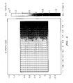
- FIG. 6 Shown in FIG. 6 is a plot showing the same reactant concentrations as in FIG. 5, with the compression/expansion wave applied by the invention 101 frozen in time.
- the transducers 115, 117 are excited using a frequency of 10 MHz.
- the plot shows enhanced mixing of the reactants when the compression/expansion wave is applied, with no additional mechanical manipulation.
- the parameters of the porous medium 103 shown in FIGs. 5 and 6 are those of Torrey paper.
- Torrey paper is a porous material used in fuel cell applications.
- Porosity is a non-dimensional quantity being the ratio of free space to the total volume of the material.
- the concentration change toward equilibration in the porous media 103 is calculated as 1.8*10 -7 per one period of vibration. The value indicates that during the time equal to one vibration period, the concentration in non-dimensional units (the ratio of the volume occupied by A or B to the total volume) has changed by 1.8*10 -7 .
- FIG. 6 shows the concentration change toward equilibrium in the porous media 103 when using the mixer 101 as 0.4*10 -5 per one period of vibration.
- mixing acceleration is approximately 22 times greater for a chosen porous media using a 10 MHz excitation having an amplitude equal to 0.1 of the sample width.
- the concentration change towards equilibrium is approximately 22 times faster than without the vibration (ratio of 0.4*10 -5 to 1.8*10 -7 ) .
- the acoustic perturbation of the porous material 103 using the compression/expansion wave of the invention accelerates the mixing of the reactants to more than 20 times that of natural diffusion.
- Multiphase flow in the porous medium 103 when subjected to the compression/expansion wave show dramatic enhancement of mixing compared to natural diffusion of the two reacting fluids inside the porous sample.
- FIG. 1 The exemplary embodiment shown in FIG. 1 is one instance of the general approach to accelerating and controlling the mixing of at least two reactants inside at least one porous medium.
- FIG. 7 Shown in FIG. 7 is an alternate embodiment of the invention 701.
- the alternative embodiment employs 4 pairs of transducer/actuators 705, 707, 709, 711, 713, 715, 717, 719.
- the wave imparted by the transducer/actuators 705, 707, 709, 711, 713, 715, 717, 719 exert force on two opposing surfaces of at least one porous medium 721 containing, at an initial stage, separate liquids A through I introduced through a micro-channel plenum (not shown).
- the motion of the invention is synchronized such that each transducer excursion is in unison.
- Transducer/actuators 705, 709, 713, 717 and 707, 711, 715, 719 may be a lower and an upper part of the same transducer assembly, respectively.
- transducers that exert force synchronously may be designed as one entity, as N/2, rather than requiring N separate transducers (one transducer for each actuator), such that one source of ultrasonic energy is divided and channeled to the required point sources of application by which synchronization is achieved.
- Modifications to the acoustic perturbation wave shape applied to the porous medium and to the frequency may be used to optimize the rate of mixing in any porous medium structure geometry.
- hybridization of the transducer syncing may further optimize mixing efficiency, where each pair of transducer/actuators 705/707, 709/711, 713/715, 717/719 may not be in complete synchronicity, or phase, with other pairs, but with each operating at a predetermined phase shift from other pairs.
- various embodiments of the invention may be employed, for example, to mix methanol and water in a reformed hydrogen fuel cell and/or a direct methanol fuel cell. Additionally, various embodiments of the invention have demonstrated the capability to mix a variety of fluids including, for example, gases, liquids, gas-liquid mixtures, etc. Other representative applications may include the mixing of fuels supplying a micro-reactor and/or micro-combustion chamber.
Landscapes
- Chemical & Material Sciences (AREA)
- Chemical Kinetics & Catalysis (AREA)
- Organic Chemistry (AREA)
- Dispersion Chemistry (AREA)
- Health & Medical Sciences (AREA)
- General Health & Medical Sciences (AREA)
- Toxicology (AREA)
- Physical Or Chemical Processes And Apparatus (AREA)
- Mixers With Rotating Receptacles And Mixers With Vibration Mechanisms (AREA)
Applications Claiming Priority (1)
| Application Number | Priority Date | Filing Date | Title |
|---|---|---|---|
| US11/507,691 US20080049545A1 (en) | 2006-08-22 | 2006-08-22 | Acoustic acceleration of fluid mixing in porous materials |
Publications (1)
| Publication Number | Publication Date |
|---|---|
| EP1892031A1 true EP1892031A1 (de) | 2008-02-27 |
Family
ID=38650077
Family Applications (1)
| Application Number | Title | Priority Date | Filing Date |
|---|---|---|---|
| EP07253229A Withdrawn EP1892031A1 (de) | 2006-08-22 | 2007-08-16 | Akustische Beschleunigung von Fluidmischungen in porösen Materialien |
Country Status (3)
| Country | Link |
|---|---|
| US (3) | US20080049545A1 (de) |
| EP (1) | EP1892031A1 (de) |
| JP (1) | JP2008049337A (de) |
Cited By (1)
| Publication number | Priority date | Publication date | Assignee | Title |
|---|---|---|---|---|
| US20100046319A1 (en) * | 2006-08-22 | 2010-02-25 | United Technologies Corporation | Acoustic Acceleration of Fluid Mixing in Porous Materials |
Families Citing this family (1)
| Publication number | Priority date | Publication date | Assignee | Title |
|---|---|---|---|---|
| FR2955508B1 (fr) | 2010-01-25 | 2012-03-30 | Corning Inc | Microreacteurs avec dispositif microfluidique plan et systeme d'application d'ultrasons ; mise en oeuvre de reactions chimiques en leur sein |
Citations (6)
| Publication number | Priority date | Publication date | Assignee | Title |
|---|---|---|---|---|
| GB1012538A (en) * | 1963-09-12 | 1965-12-08 | Philips Electronic Associated | Improvements in or relating to ultrasonic irradiation devices |
| JPS6320026A (ja) * | 1986-07-14 | 1988-01-27 | Oki Electric Ind Co Ltd | 高周波混合方法及び装置 |
| DE19756874A1 (de) * | 1997-12-19 | 1999-06-24 | Basf Ag | Vorrichtung zum Herstellen von dispersen Stoffgemischen mittels Ultraschall und Verwendung einer derartigen Vorrichtung |
| EP1541227A2 (de) * | 2003-12-12 | 2005-06-15 | United Technologies Corporation | Akustische Vorrichtung zur Sauerstoffentfernung von Fuel |
| EP1724005A1 (de) * | 2004-03-10 | 2006-11-22 | Olympus Corporation | Flüssigkeitsrührvorrichtung |
| WO2007063314A1 (en) * | 2005-11-30 | 2007-06-07 | Specialist Process Technologies Limited | Gas-liquid contactor |
Family Cites Families (53)
| Publication number | Priority date | Publication date | Assignee | Title |
|---|---|---|---|---|
| US2831785A (en) * | 1958-04-22 | Jfzgz | ||
| US1751087A (en) * | 1928-07-05 | 1930-03-18 | Jackson Corwill | Agitator for concrete molds |
| US1774896A (en) * | 1929-05-17 | 1930-09-02 | Joseph E Miller | Vibrator for molds |
| US2145198A (en) * | 1934-04-21 | 1939-01-24 | Ig Farbenindustrie Ag | Device for mechanically treating thixotropes |
| US2717768A (en) * | 1947-05-08 | 1955-09-13 | Rech S Ind Et Chimiques Soc Et | Installation for the extraction and treatment of fatty vegetable materials |
| US2578377A (en) * | 1947-06-24 | 1951-12-11 | Sinclair Refining Co | Catalytic conversion of hydrocarbons with finely divided catalysts utilizing sonic vibrations |
| US2578505A (en) * | 1948-03-02 | 1951-12-11 | Sperry Prod Inc | Supersonic agitation |
| US2702691A (en) * | 1949-05-06 | 1955-02-22 | James Knights Company | Generator system for producing rotating vibratory field |
| US2876083A (en) * | 1953-06-29 | 1959-03-03 | Prietl Franz | Process of producing crystals from particles of crystallizable substance distributedin a liquid |
| US2854012A (en) * | 1954-01-15 | 1958-09-30 | Telephonics Corp | Sonic energy apparatus |
| US2864592A (en) * | 1955-03-07 | 1958-12-16 | Bendix Aviat Corp | Liquid-vibrating apparatus |
| US2891176A (en) * | 1955-07-13 | 1959-06-16 | Branson Instr | Compressional wave generating apparatus |
| US2874316A (en) * | 1957-01-04 | 1959-02-17 | Blackstone Corp | Ultrasonic transducers |
| US3133652A (en) * | 1960-02-15 | 1964-05-19 | Chain Belt Co | Tunable car vibrator |
| US3329408A (en) * | 1965-03-29 | 1967-07-04 | Branson Instr | Transducer mounting arrangement |
| US3368610A (en) * | 1965-07-08 | 1968-02-13 | Atomic Energy Commission Usa | Superheating prevention and boiling control |
| US3301535A (en) * | 1966-01-04 | 1967-01-31 | American Sterilizer Co | Ultrasonic washing machine and transducer therefor |
| US3673441A (en) * | 1969-05-01 | 1972-06-27 | Honeywell Inc | Control apparatus |
| US3583677A (en) * | 1969-08-28 | 1971-06-08 | Electro Sonic Oil Tools Inc | Electro-mechanical transducer for secondary oil recovery |
| US4047060A (en) * | 1971-09-07 | 1977-09-06 | Motorola, Inc. | Acoustic transducer with elastomeric coupling |
| US3949349A (en) * | 1972-04-13 | 1976-04-06 | Fred M. Dellorfano, Jr. | Dual electroacoustic transducers |
| US3804329A (en) * | 1973-07-27 | 1974-04-16 | J Martner | Ultrasonic generator and atomizer apparatus and method |
| GB1506502A (en) * | 1975-04-10 | 1978-04-05 | Nat Res Dev | Acoustic wave oscillators |
| US4168295A (en) * | 1975-11-20 | 1979-09-18 | Vernon D. Beehler | Apparatus for enhancing chemical reactions |
| US4071225A (en) * | 1976-03-04 | 1978-01-31 | Holl Research Corporation | Apparatus and processes for the treatment of materials by ultrasonic longitudinal pressure oscillations |
| US4140936A (en) * | 1977-09-01 | 1979-02-20 | The United States Of America As Represented By The Secretary Of The Navy | Square and rectangular electroacoustic bender bar transducer |
| US4433916A (en) * | 1982-11-02 | 1984-02-28 | Hall Mark N | Acoustic resonator having transducer pairs excited with phase-displaced energy |
| JPS5987026A (ja) * | 1982-11-09 | 1984-05-19 | Nishi Nippon Flex Kk | 超音波連続混和装置 |
| JPS62186928A (ja) * | 1986-02-13 | 1987-08-15 | Mitsubishi Electric Corp | 溶解装置 |
| JPS62247870A (ja) * | 1986-04-21 | 1987-10-28 | 多賀電気株式会社 | 超音波振動子の駆動制御方法 |
| US4782910A (en) * | 1986-05-23 | 1988-11-08 | Mobil Oil Corporation | Bi-polar bender transducer for logging tools |
| JPS6410163A (en) * | 1987-07-02 | 1989-01-13 | Nec Corp | Biosensor |
| US5123433A (en) * | 1989-05-24 | 1992-06-23 | Westinghouse Electric Corp. | Ultrasonic flow nozzle cleaning apparatus |
| US4949316A (en) * | 1989-09-12 | 1990-08-14 | Atlantic Richfield Company | Acoustic logging tool transducers |
| JP3104143B2 (ja) * | 1992-02-14 | 2000-10-30 | 耕司 戸田 | 超音波攪拌装置 |
| JPH05301038A (ja) * | 1992-04-24 | 1993-11-16 | Shimada Phys & Chem Ind Co Ltd | 超音波撹拌装置 |
| US6010592A (en) | 1994-06-23 | 2000-01-04 | Kimberly-Clark Corporation | Method and apparatus for increasing the flow rate of a liquid through an orifice |
| US5641228A (en) * | 1995-06-01 | 1997-06-24 | Planisol, Inc. | Transducer mounting assembly |
| US5890802A (en) * | 1997-02-21 | 1999-04-06 | University Of Washington | Piezo-ceramic actuator-driven mixing device |
| JP3514358B2 (ja) | 1997-05-08 | 2004-03-31 | 東海ゴム工業株式会社 | 管体用防音カバー及びその製造方法 |
| US5956293A (en) * | 1997-05-27 | 1999-09-21 | Raytheon Company | Flexural plate sound transducer having low resonant frequency |
| TW571505B (en) | 2001-08-09 | 2004-01-11 | Asulab Sa | Piezoelectric motor |
| JP2003265939A (ja) * | 2002-03-13 | 2003-09-24 | Yasushi Takeda | 気泡生成装置、気泡生成方法、微粒子生成装置、及び微粒子生成方法 |
| US6910797B2 (en) * | 2002-08-14 | 2005-06-28 | Hewlett-Packard Development, L.P. | Mixing device having sequentially activatable circulators |
| FR2845619B1 (fr) * | 2002-10-15 | 2005-01-21 | Christophe Dominique No Arnaud | Dispositif et procede de fabrication d'un melange, d'une dispersion ou emulsion d'au moins deux fluides reputes non miscibles |
| US6986601B2 (en) * | 2003-05-13 | 2006-01-17 | Motorola, Inc. | Piezoelectric mixing method |
| JP4566669B2 (ja) * | 2004-09-21 | 2010-10-20 | 日本碍子株式会社 | 気泡噴射装置 |
| DE102005043034A1 (de) * | 2005-09-09 | 2007-03-15 | Siemens Ag | Vorrichtung und Verfahren zur Bewegung einer Flüssigkeit |
| US20080049545A1 (en) * | 2006-08-22 | 2008-02-28 | United Technologies Corporation | Acoustic acceleration of fluid mixing in porous materials |
| JP4300536B2 (ja) * | 2006-09-01 | 2009-07-22 | Jfeエンジニアリング株式会社 | 音波による気泡発生方法及び気泡発生装置 |
| FR2905990A1 (fr) | 2006-09-20 | 2008-03-21 | Snecma Sa | Systeme propulsif a pylone integre pour avion. |
| CN101980769B (zh) * | 2008-03-28 | 2013-06-12 | 爱科来株式会社 | 液体搅拌方法、液体搅拌系统以及盒 |
| WO2010102301A1 (en) * | 2009-03-06 | 2010-09-10 | Jennifer Hollenstein | Method and apparatus for suspending magnetic microparticles |
-
2006
- 2006-08-22 US US11/507,691 patent/US20080049545A1/en not_active Abandoned
-
2007
- 2007-08-16 EP EP07253229A patent/EP1892031A1/de not_active Withdrawn
- 2007-08-17 JP JP2007212539A patent/JP2008049337A/ja active Pending
-
2009
- 2009-10-28 US US12/607,486 patent/US8408782B2/en not_active Expired - Fee Related
-
2013
- 2013-03-15 US US13/832,151 patent/US8789999B2/en not_active Expired - Fee Related
Patent Citations (6)
| Publication number | Priority date | Publication date | Assignee | Title |
|---|---|---|---|---|
| GB1012538A (en) * | 1963-09-12 | 1965-12-08 | Philips Electronic Associated | Improvements in or relating to ultrasonic irradiation devices |
| JPS6320026A (ja) * | 1986-07-14 | 1988-01-27 | Oki Electric Ind Co Ltd | 高周波混合方法及び装置 |
| DE19756874A1 (de) * | 1997-12-19 | 1999-06-24 | Basf Ag | Vorrichtung zum Herstellen von dispersen Stoffgemischen mittels Ultraschall und Verwendung einer derartigen Vorrichtung |
| EP1541227A2 (de) * | 2003-12-12 | 2005-06-15 | United Technologies Corporation | Akustische Vorrichtung zur Sauerstoffentfernung von Fuel |
| EP1724005A1 (de) * | 2004-03-10 | 2006-11-22 | Olympus Corporation | Flüssigkeitsrührvorrichtung |
| WO2007063314A1 (en) * | 2005-11-30 | 2007-06-07 | Specialist Process Technologies Limited | Gas-liquid contactor |
Non-Patent Citations (3)
| Title |
|---|
| [WIKIPEDIA - THE FREE ENCYCLOPEDIA]: "Linear actuator", pages 1 - 5, XP002458017, Retrieved from the Internet <URL:http://en.wikipedia.org/wiki/Linear_actuator> [retrieved on 20071109] * |
| [WIKIPEDIA - THE FREE ENCYCLOPEDIA]: "Piezoelectricity", pages 1 - 10, XP002458016, Retrieved from the Internet <URL:http://en.wikipedia.org/wiki/Piezoelectric> [retrieved on 20071109] * |
| [WIKIPEDIA - THE FREE ENCYCLOPEDIA]: "Ultrasonic sensors", pages 1 - 2, XP002458015, Retrieved from the Internet <URL:http://en.wikipedia.org/wiki/Ultrasonic_transducer> [retrieved on 20071109] * |
Cited By (3)
| Publication number | Priority date | Publication date | Assignee | Title |
|---|---|---|---|---|
| US20100046319A1 (en) * | 2006-08-22 | 2010-02-25 | United Technologies Corporation | Acoustic Acceleration of Fluid Mixing in Porous Materials |
| US8408782B2 (en) * | 2006-08-22 | 2013-04-02 | United Technologies Corporation | Acoustic acceleration of fluid mixing in porous materials |
| US8789999B2 (en) | 2006-08-22 | 2014-07-29 | United Technologies Corporation | Acoustic acceleration of fluid mixing in porous materials |
Also Published As
| Publication number | Publication date |
|---|---|
| US8408782B2 (en) | 2013-04-02 |
| US8789999B2 (en) | 2014-07-29 |
| US20100046319A1 (en) | 2010-02-25 |
| JP2008049337A (ja) | 2008-03-06 |
| US20080049545A1 (en) | 2008-02-28 |
| US20130201781A1 (en) | 2013-08-08 |
Similar Documents
| Publication | Publication Date | Title |
|---|---|---|
| EP3450006B1 (de) | Resonanzschwingsmischen | |
| US7866878B2 (en) | Method for resonant-vibratory mixing | |
| US4118797A (en) | Ultrasonic emulsifier and method | |
| Bengtsson et al. | Ultrasonic agitation in microchannels | |
| Frommelt et al. | Microfluidic mixing via acoustically driven chaotic advection | |
| KR101380585B1 (ko) | 초음파 처리 장치, 및 초음파 처리 챔버 및 방법 | |
| US20110127164A1 (en) | Non-invasive acoustic technique for mixing and segregation of fluid suspensions in microfluidic applications | |
| US8789999B2 (en) | Acoustic acceleration of fluid mixing in porous materials | |
| JP5731570B2 (ja) | 攪拌装置および攪拌装置によって混合する方法 | |
| Won et al. | Acoustic bubble-induced microstreaming for biochemical droplet mixing enhancement in electrowetting (EW) microfluidic platforms | |
| CN112538426B (zh) | 一种声波驱动的气泡共振与微流场激励的装置和方法 | |
| Iida et al. | Bubble motions confined in a microspace observed with stroboscopic technique | |
| Qian et al. | Dual-Function Multichannel Acoustofluidic Particle Manipulation Enabled by a PMUT Array | |
| WO2013184075A1 (en) | Microfluidic devices and methods for providing an emulsion of a plurality of fluids | |
| US20040257907A1 (en) | Method and apparatus for mixing fluids | |
| JP2005169219A (ja) | マイクロミキサ | |
| Ishizuka et al. | Design and evaluation of a cylindrical micromixer using ultrasonic vibration in torsional vibration mode | |
| Xia et al. | Integrated aeroelastic vibrator for fluid mixing in open microwells | |
| Demori et al. | MEMS device with piezoelectric actuators for driving mechanical vortexes in aqueous solution drop | |
| JPH11226377A (ja) | 撹拌混合装置 | |
| JP2004076608A (ja) | 改質燃料用ディーゼルエンジン | |
| Kar et al. | Emerging and Unconventional Mixing Systems | |
| Al-Mudhafar et al. | Design of Hybrid Micromixer for Biomedical Applications | |
| Liu et al. | Acoustic microstreaming for biological sample mixing enhancement | |
| JP2006322463A (ja) | 燃料改質装置および燃料改質方法 |
Legal Events
| Date | Code | Title | Description |
|---|---|---|---|
| PUAI | Public reference made under article 153(3) epc to a published international application that has entered the european phase |
Free format text: ORIGINAL CODE: 0009012 |
|
| AK | Designated contracting states |
Kind code of ref document: A1 Designated state(s): AT BE BG CH CY CZ DE DK EE ES FI FR GB GR HU IE IS IT LI LT LU LV MC MT NL PL PT RO SE SI SK TR |
|
| AX | Request for extension of the european patent |
Extension state: AL BA HR MK YU |
|
| AKX | Designation fees paid | ||
| REG | Reference to a national code |
Ref country code: DE Ref legal event code: 8566 |
|
| STAA | Information on the status of an ep patent application or granted ep patent |
Free format text: STATUS: THE APPLICATION IS DEEMED TO BE WITHDRAWN |
|
| 18D | Application deemed to be withdrawn |
Effective date: 20080828 |